Sportop E450 Operation manual
MODEL:
E450
Owner's Operating Manual

POLYFOAM(1)
Warning:
POLYFOAM(3)
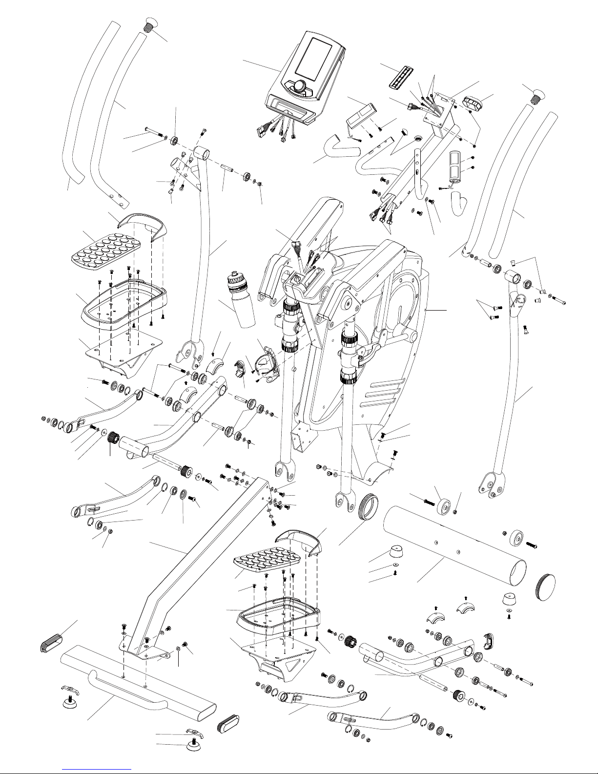
Unpacking Caution:
1.Lay the box down,and unpack all the parts except the main frame (A).
2.Remove the top polyfoam (#1) and side polyfoams (#2 & #3) ,leaving the main
frame (A) and the bottom polyfoam (#4).
POLYFOAM(2)
POLYFOAM(4)
- 1 -
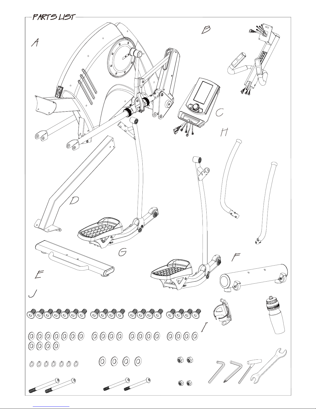
Main frame
Tool
G1 Pedal supporting
tube (L)
G2 Pedal supporting
tube (R)
Console
Central supporting
tube
Bottle holder
(J2) Washer M8X16X1.2T
(J5) Nut M10
(J3) Screw M10X75
(J4) Washer M10X19X2.0T
(J1) Screw M8X15
(J6) Screw M8X70
6m/m 5m/m6m/m
13&17
H1 Handle bar (L)
H2 Handle bar (R)
(J7) Nut M8
Rear stabilizer
Connecting tube
Front stabilizer
I1
BottleI2
(J16) Washer M8
- 2 -
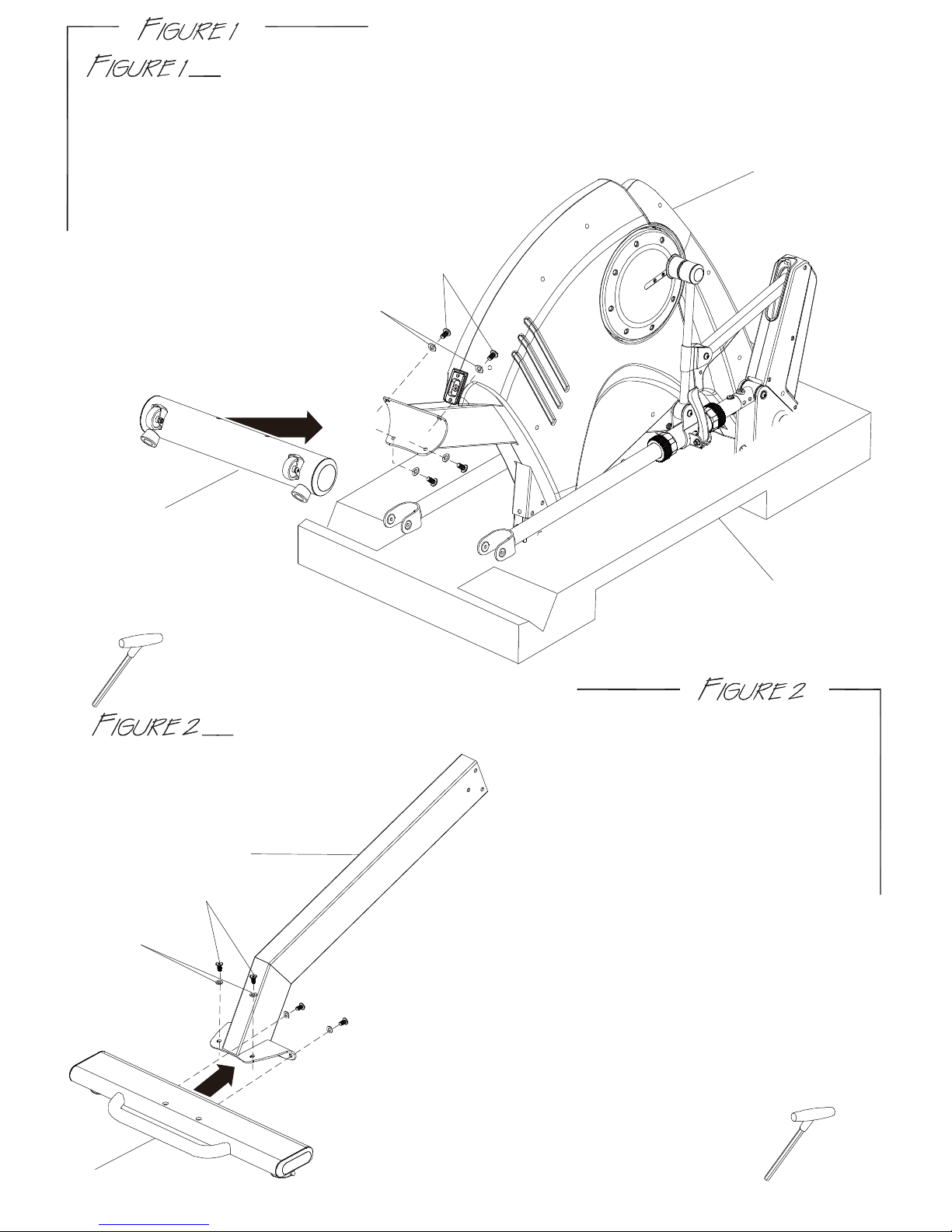
FRONT STABILIZER (F) ASSEMBLY
Step 1. Fix the front stabilizer (F) with the main frame (A) together
using 4 sets of screws (J1) &washer (J2).
POLYFOAM(4)
CONNECTING TUBE (D) & REAR STABILIZER (E) ASSEMBLY
F
A
D
E
J1
J2
Step 1. Fix the rear stabilizer (E) with the
connecting tube (D) together
using 4 sets of screws (J1) &
washer (J2).
Use Tool
5m/m
Use Tool
5m/m
J1
J2
-3-
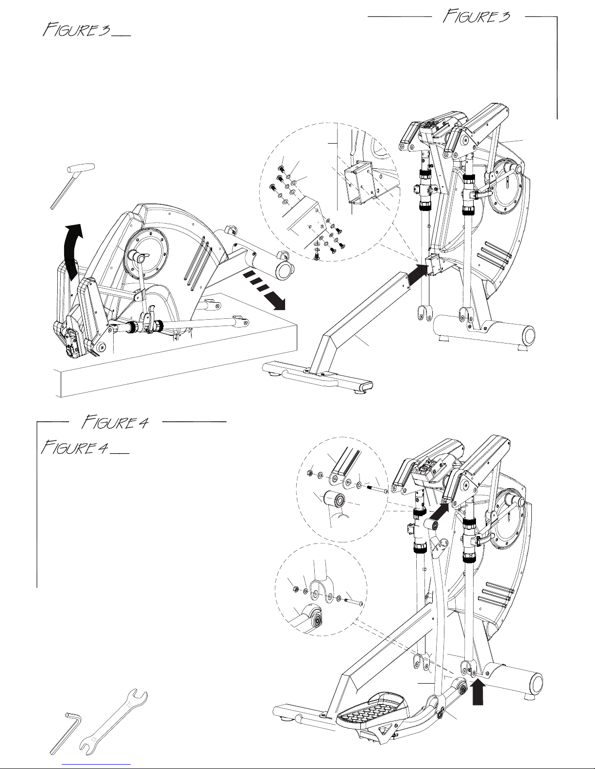
PEDAL SUPPORTING TUBE ASSEMBLY
CONNECTING TUBE (D&E) AND MAIN FRAME ASSEMBLY
Step 1. Raise the main frame (A) by 2 people and then remove the Polyfoam (#4) as the
diagram shown.
Step 2. Fix the connecting tube (D&E) onto the main frame (A) by using 7 sets of screws (J1) ,
spring washer (J16) ,and washer (J2).
Step 3. Tighten all the screws (J1) in Figure 1 to Figure 3.
VIEW B
A
J5
J3
G2
VIEW C
J7
J6
G2
J2
J4
D&E
A
G2
Step 1. Connect the right pedal supporting
tube (G2) with the main frame (A)
and fix them using screw (J3),washer
(J4),and nut (J5) as show in VIEW B.
Step 2. Referring to the VIEW C shown,tighten
screw (J3) and nut (J5) after locking
screw (J6),washer (J2),and nut(J7)
in VIEW C.
If step 2 is diffcult to fix,try to disassemble
another screw (J6) then fix again.
Step 3. The left pedal supporting tube
(G1) assembly is the same as the
right side.
Remember to tighten all the screws(J3*2 & J6*4)
in step 1 to step 3.
Use Tool
5m/m
Use Tool
6m/m
13&17
another J6
VIEW A
J1
J2
J16
A
D

-4-
HANDLE BAR ASSEMBLY
Step 1. Remove the six preinstalled (J8&J9)
Step 2. Assemble the left handle bar (H1)
i nto the main frame (A) and u
se
Step 3. The right assembly (H2) is the same
as the left side.
CENTRAL SUPPORTING TUBE
AND BOTTLE HOLDER ASSEMBLY
Step 1. Connect wires (B1&A2-1*2&B2) from the central
Make sure that the wires A2&A2-1 are connected the
right side as the sticker shown.
supporting tube (B) with wires (A1&A2*2&A3)
from the main frame (A)as the shown in VIEW E.
Step 2. Use the 4 screws (J1&J2) to fix the central
supporting tube (B) onto the main frame (A)
and tighten all the 4 screws (J1&J2) as the
shown in VIEW F.
Step 4. Use screws (J10) to fix bottle holder(I) onto the
the main frame (A).
A
J1
A
B
H1
J9*6
J8*6
VIEW D
J8
J8
J8*6
J9*6
screws from the left handle bar (H1).
the two 6mm Allan wrench to fix
all screw (J8&J9) referring to the
shown in VIEW D.
J8 J9
J2
A2-1*2
B1
A1
B2
A2*2
A3
I1
J10
VIEW E
VIEW F
VIEW E
Use Tool
Use Tool
6m/m 6m/m
5m/m6m/m
Note: Before Figure 5, remove the four preassembled screws and the bracket from the top of the main frame(A) .

-5-
CONSOLE ASSEMBLY
Step 1. Remove 4pieces of screws (C1) from console (C).
Step 2. Connect sensor wires (B1),handle pulse wire (B4),
electronic knob wire (B2),and LED sensor wire (B3)
from the main frame (A) to the console (C) as the
shown in VIEW G.
Make sure that the wires are connected together properly.
Push and store excess wires back into the central
supporting tube(B).
Step 3. Fix the console (C) onto the central supporting
tube (B) by using the screws (C1).
When floor is uneven,using the adjustment knob
under the rear stablilzer (E) to adjust it.
A3
HOW TO FIX BOTH PEDAL
SUPPORTING TUBES (G1 & G2)
While the machine is idle,turn the
ELECTRONIC KNOB (A3) to become “LOCK”
status and make the pedal supporting
tube (G1&G2) to be fixed gradually,also the
console (C) will be locked that can’t be used
at the same time until the knob(A3) turn back
to “UNLOCK”.
The machine should always be at “LOCK”
position when NOT in use.It would prevent
the children or user from being hurt.
WARNING:The electronic knob only works when
the machine is electric.
C1
C
B
B1 B2
B3 B4*2
VIEW G
Use Tool
6m/m

-6-
HOW TO TRANSPORT THE ELLIPTICAL
If the machine needs to be transported to a different location,make sure that the ELECTRONIC
KNOB (A3) is under “LOCK” status .That you can turn off the switch,pull out the power cord
from the electricity outlet and put away carefully. Then lift up the handle bar on the rear
stablilzer (E) until the front transport wheels are touching the ground. You can move it to the
desired location.After transportation,gently set the machine down at its new location.
WARNING:The unlock knob status would create severe damage to the user.
ASSEMBLY FOR THE POWER CORD
Attach the power cord jacket onto the socket on
the main frame (A) before insert the plug into the
electricity outlet.

-7-
HOW TO ADJUST STRIDE BY PUSH ROD BRACKET
Step 1. Depending on the personal demand to change the stride in different distance
18”, 20”, 22”, 24”,and 26” as the LED SENSOR displayed.
Step 2. Turn the handle on the push rod bracket out,then you can pull it up or down to
the stride as you want. At the same time,the LED SENSOR will light the LED which
stride you choiced.
Step 3. After changing the stride,turn the handle on the push rod bracket back to fix it
tightly.
WARNING:FOR YOUR SAFETY,never change the stride or even turn the handle on the
push rod bracket while the machine is in motion,only when it is at a full
complete stop.
FOR YOUR HEALTHLY,make the left side and the right side at the same stride.
PEDAL STRIDE
A
J1*19
J2*27
J1*19
J16*13
J2*27
J1*19
J2*27
J1*19
J2*27
B
B1 B2
B3 B4*2
B5
B9
B6*2
B6-1*4
B7*2 B8*2
C
C1*4
D
E
F
E1*2
E3*2
E2*2
F1*2
F2*2
F3*2
F4*2
F5*2
F6*2 F7*2
G1
G2
G3*4
G4*2
J3*2
J4*4
J5*2
A6-5*18
A6-8*12
G5*2
G5*2
A28-2*6
J6*4
J2*27
J7*4
G7*4
G8*4
G9*2
G10*4
G11*4
G12*4
G30*4
G14*2
G15-1*2
G11*4
G6*4
G16*8
G17*8
G18*4
G13*4
G19*4
G20
G24
G21
G22
G23
G25
G26
G27
G28*12
G29*6
J8*6
J9*6
J8*6
J9*6
H1
H2
H3*2
H4*2
H4*2
H3*2
A1 A2*2 A2-1*2
I1
J10*2
-8-
G6*4
G15*2
G15*2
G15-1*2
I2

A
A3
A3-1
A4
A6*2
A5
A4-1*2
A4-4*2
A4-3*2
A4-5*2
A4-2*4
A4-4*2
A4-7*2
A4-3*2
A4-2*4
A6*2
A6-1*6
A6-2*22
A6-3*12
A6-4*12
A6-5*18
A6-6*12
A6-7*8
A7-1*2
A7*2
A7-4
A7*2
A7-2*2
A7-3*2
A8*2 A9*2
A10*2
A11
A12
A21
A17
A13 A11-1*4
A11-3*4
A11-7
A11-4*2
A11-2*4
A8*2
A9*2
A14
A15
A20
A16
A16-4
A15-1*2
A15-2
A15-3
A15-5
A15-6
A15-4*2 A16-1*2
A16-2
A17-1
A17-2
A18
A18-1*4
A19*2
A19-1*4
A19*2
A20-1*2
A22
A24
A23
A25*2
A25*2
A26*2
A27*2
A26*2
A27*2
A28*2
A28-1*2
A28-2*6
A28-3*6
A29*2
A28*2
A29*2
A6-5*18
A6-8*12
A6-2*22
A28-4*2
A29-1*2
A29-2*2
A29-3*2
A29-4*2
A29-6*4
A29-9*6
A30*2
A30-1*4
A30-2*4
A30-3*2
A30-4*2
A30-5*4
A30-6*2
A30-7*2
A30-8*2
A30-9*2
A30-10*2
A30-11*2
A30-12*4
A30-13*2
A30-14*2
A17-7
A17-8
A17-6
A17-3
A17-5
A17-4
A18-2
A16-3
A18-3
A18-4
A18-5
A30-15*2
A30-17*2
A30-16*2
A20-2
-9-
A4-6*2
A7-5
A16-5
A16-6
A16-7
J11*6
J13*2
J12*8
J14*7
J14*7
J14*7
J14*7
J14*7
J14*7
J15*10
J15*10
J15*10
J15*10
J15*10
J15*10
J15*10
J15*10
A7-6*2
A7-6*2
J15*10
J11*6
J11*6
J16*13
A30
-18*4
A30-19*2
A9-1*2
A11-5
A11-6

-10-
P/N DESCRIPTION Qty P/N DESCRIPTION Qty
A MAIN FRAME 1 A15-3 CLIP C12 1
A1 MOTOR SENSOR WIRE 1200mm 1 A15-4 BEARING 6202ZZ 2
A2 SENSOR WIRE 500mm 2 A15-5 WASHER 1
A2-1 SENSOR WIRE 250mm 2 A15-6 CLIP C15 1
A3 ELECTRONIC KNOB 1 A16 PRESSING PIPE 1
A3-1 ELECTRONIC KNOB STICKER 1 A16-1 BEARING 6203Z 2
A4 OSCILLATING AXLE BASE(L) 1 A16-2 CLIP 1
A4-1 END CAP 2 A16-3 SPRING 1
A4-2 BEARING 6905ZZ 4 A16-4 PIPE 3
A4-3 SCREW CAP 2 A16-5 WASHER 3
A4-4 SCREW M8×20 2 A16-6 SPRING WASHER 3
A4-5 WASHER M8×28×2T 2 A16-7 SCREW 3
A4-6 WASHER M8×16×1.2T 2 A17 MAGNETIC HOUSING 1
A4-7 SPRING WASHER M8 2 A17-1 SCREW M8×52 1
A5 OSCILLATING AXLE BASE(R) 1 A17-2 NUT M8 1
A6 FRONT CONNECTING SHAFT 2 A17-3 SCREW M6×65 1
A6-1 SCREW M8×50 6 A17-4 NUT M6 1
A6-2 WASHER M8 22 A17-5 SPRING 1
A6-3 BUSH 8( 11.9+ 15) 12 A17-6 WASHER M7×22×2.5T 1
A6-4 CLIP(R36) 12 A17-7 WASHER M6×18 1
A6-5 BEARING 6201ZZ TPX 18 A17-8 NUT M6 1
A6-6 BEARING SLEEVE 42×3T 12 A18 MOTOR 1
A6-7 NUT M8 8 A18-1 SCREW 4
A6-8 BEARING HOUSING 12 A18-2 TENSION CABLE 1
A7 CRANK CONNECTING SHAFT 2 A18-3 SENSOR WIRE 600mm 1
A7-1 BEARING 2203 MRB 2 A18-4 SENSOR WIRE HOUSING 1
A7-2 CLIP(R40) 2 A18-5 SCREW 1
A7-3 NUT M10 2 A19 TURING PLATE 2
A7-4 END CAP 1 A19-1 SCREW M5×12 4
A7-5 END CAP 1 A20 DC JACK HOUSING 1
A7-6 WASHER M10×19×2T 2 A20-1 SCREW 2
A8 CRANK (#1) 2 A20-2 DC WIRE 600mm 1
A9 SCREW M10×30 2 A21 MAIN CHAIN COVER(L) 1
A9-1 NUT M10 2 A22 MAIN CHAIN COVER(R) 1
A10 FLAT KEY 2 A23 SMALL CHAIN COVER(L) 1
A11 AXLE (#1) 1 A24 SMALL CHAIN COVER(R) 1
A11-1 WASHER M6 4 A25 END CAP 2
A11-2 NUT M6 4 A26 OSCILLATING AXLE BASE COVER(L) 2
A11-3 SCREW M6×18 4 A27 OSCILLATING AXLE BASE COVER(R) 2
A11-4 BEARING 6005ZZ 2 A28 FRONT PEDAL SUPPORTING TUBE(UP) 2
A11-5 BUSH 25.2× 29.2×M5 (#1) 1 A28-1 SCREW M8×75 2
A11-6 BUSH 25.2× 29.2×M46.4 (#1) 1 A28-2 BUSH 12× 7.9×49.7 6
A11-7 BEARING NUT M25×P1.5 (#1) 1 A28-3 SCREW M8×15 6
A12 BELT WHEEL 350 1 A28-4 END CAP 2
A13 MAGNETIC 15×7 1 A29 FRONT PEDAL SUPPORTING TUBE(UNDER) 2
A14 BELT 1371mm×J6 1 A29-1 BUMPER(+SCREW) 4
A15 FLYWHEEL (12KG) 1 A29-2 SENSOR HOUSING(UNDER) 2
A15-1 M10 2 A29-3 SENSOR HOUSING(UP) 2
A15-2 AXLE CENTER 1 A29-4 SENSOR 2
(#1) : Changed at April 03, 2013

-11-
P/N DESCRIPTION Qty P/N DESCRIPTION Qty
A29-6 SCREW M4×13 4 G4 BUSH 16.98× 9.9×49.7 2
A29-9 SCREW M3×8 8 G5 LOWER PEDAL SUPPORTING TUBE 2
A30 PUSH ROD BRACKET 2 G6 SCREW M8×25 4
A30-1 ADJUSTMENT KNOB 4 G7 PEDAL REINFORCEMENT COVER 4
A30-2 ADJUSTMENT NUT 4 G8 SCREW M4×10 4
A30-3 HANDLE 2 G9 PEDAL TUBE END CAP 2
A30-4 SCREW M8×45 2 G10 AXLE BUSHING 4
A30-5 BUSH 4 G11 SCREW M8×20 4
A30-6 NYLON NUT M8 2 G12 SPRING WASHER M8 4
A30-7 SCREW M6×10 2 G13 WASHER M8 4
A30-8 SPRING 2 G14 BUSH 2
A30-9 BLOCK 2 G15 LEFT SIDE PEDAL SUPPORTING TUBE 2
A30-10 SOCKET SET SCREW M4×4 2 G15-1 RIGHT SIDE PEDAL SUPPORTING TUBE 2
A30-11 MAGNETIC HOUSING 2 G16 CLIP(R28) 8
A30-12 SCREW M4×8 4 G17 BEARING 6001ZZ 8
A30-13 SPRING 2 G18 WASHER 4
A30-14 MAGNETIC 2 G19 NUT M8 4
A30-15 NYLON SCREW COVER M6 2 G20 PEDAL BRACKET(L) 1
A30-16 HANDLE BLOCK-A 2 G21 PEDAL(L) 1
A30-17 HANDLE BLOCK-B 2 G22 CUSHION PAD(L) 1
A30-18 WASHER 4 G23 FRONT PEDAL COVER(L) 1
A30-19 MAGNETIC 1 G24 PEDAL BRACKET(R) 1
B CENTRAL SUPPORTING TUBE 1 G25 PEDAL(R) 1
B1 SENSOR WIRE 650mm 1 G26 CUSHION PAD(R) 1
B2 ELECTRONIC KNOB WIRE 700mm 1 G27 FRONT PEDAL COVER(R) 1
B3 LED SENSOR WIRE 350mm 1 G28 SCREW M6×12 12
B4 HANDLE PULSE WIRE 850mm 2 G29 SCREW M4×20 6
B5 LED SENSOR 1 G30 WASHER M8×28×2.0T 4
B6 HANDLE PULSE 2 H1 HANDLE BAR(L) 1
B6-1 SCREW 4 H2 HANDLE BAR(R) 1
B7 SPONGE HDR 200mm 2 H3 SPONG HDR 655mm 2
B8 END CAP 2 H4 HANDLE BAR END CAP 2
B9 END CAP 1 I1 BOTTLE HOLDER 1
C CONSOLE 1 I2 BOTTLE 1
C1 SCREW M5×10 4 J1 SCREW M8×15 19
D CONNECTING TUBE 1 J2 WASHER M8×16×1.2T 27
E REAR STABILIZER 1 J3 SCREW M10×75 2
E1 END CAP 2 J4 WASHER M10×19×2.0T 4
E2 NUT 2 J5 NUT M10 2
E3 ADJUSTED END 50 2 J6 SCREW M8×70 4
F FRONT STABILIZER 1 J7 NUT M8 4
F1 END CAP 2 J8 HANDLE BAR SCREW 6
F2 FIX CUSHION 50 TPR 2 J9 HANDLE BAR SCREW 6
F3 WASHER M6×19×2T 2 J10 BOTTLE HOLDER SCREW 2
F4 SCREW M5×16 2 J11 SCREW M4×20 6
F5 TRANSPORTATION WHEEL 2 J12 NUT M4 8
F6 SCREW M8×40 2 J13 SCREW M4×45 2
F7 NUT M8 2 J14 SCREW M4×25 7
G1 PEDAL SUPPORTING TUBE(L) 1 J15 SCREW M4×18 10
G2 PEDAL SUPPORTING TUBE(R) 1 J16 SPRING WASHER M8 13
G3 BEARING 6003ZZ 4 K ADAPTOR 1

BUTTON FUNCTIONS
DISPLAY FUNCTIONS
TIME Time will count up from 00:00 to maximum 99:00 with each increment
is 1 minute.
SPEED Displays current training speed. Maximum speed is 99.9 KM/H or
ML/H.
RPM Displays the Rotation Per Minute. Display range 0~100 RPM
DISTANCE Accumulates total distance from 00:0 up to 99.9 KM or ML. The user
may preset target distance data by turning the UP/DOWN joggle wheel.
Each incensement is 0.1KM or ML.
UP To make upward adjustment to each function data or increase
training resistance.
DOWN To make downward adjustment to each function data or decrease
training resistance.
ENTER To confirm all settings.
START
/ STOP
RESET To reset current setting and have the monitor switch to initial
training mode for selection. Press the RESET button for 2 seconds
under standby mode for a Total Reset.
RECOVERY To active RECOVERY function.
To start or stop workout.
Turn the START/ STOP joggle wheel under standby mode,
it can be a quick start key to the Manual Program.

CALORIES Accumulates calories consumption during training from 0 to maximum
990 calories. Each unit for increase or decrease is 10 KCL.
(This data is a rough guide for comparison of different exercise sessions
which can not be used in medical treatment.)
PULSE User may set up target pulse from 0 - 30 to 230
WATTS Display current workout watts. Display range 0~999.
POWER ON
1. Connect power supply to the monitor or press the RESET button for 2 seconds, the LCD
will display all segment with a long- beep sound for 2 seconds and display 78.0 in below
(FIGURE 1 & 2).
2. User may turn the UP/DOWN joggle wheel to select User 1~4 and press ENTER for
confirmation (FIGURE 3~4).
And then preset user information for SEX, AGE, HEIGHT and WEIGHT. (FIGURE 4~7)
FIGURE 1 FIGURE 2 FIGURE 3 FIGURE 4
FIGURE 5 FIGURE 6 FIGURE 7 FIGURE 7
PROGRAMMING MODE
1. Program selections are MANUAL PROGRAM USER PROGRAM H.R.C. WATT
(FIGURE 8~12)

2. Use UP/DOWN joggle wheel to select the program you want and press ENTER to confirm.
Or press START/STOP button to start MANUAL mode immediately.
FIGURE 8 FIGURE 9 FIGURE 10 FIGURE 11
FIGURE 12
QUICK START IN MANUAL
1. Press ENTER to enter MANUAL program, and the screen is blinking (FIGURE 13).
2. Press START/STOP to start exercising. The resist level is adjustable during exercising
(FIGURE 14).
3. User can press START/ STOP to stop exercising
FIGURE 13 FIGURE 14

MANUAL MODE
1. After selecting MANUAL mode (FIGURE 13), user can use UP/DOWN joggle wheel to
increase or decrease level (from 1 to 16) and press ENTER to confirm.
2. User may preset exercise data (TIME, DISTANCE, CALORIES, PULSE), and press
START/STOP to start exercise.
User can press RESET to return to the MANUAL setting
3. Level is adjustable during training.
FIGURE 13 FIGURE 14 FIGURE 15 FIGURE 16
FIGURE 17 FIGURE 18 FIGURE 19 FIGURE 20
USER SELECT U1-U4
PRESS
RESET 3 SEC
TO RESET
CLOCKWISE OR
ANTI-CLOCKWISE
MANUAL mode
PRESS
ENTER
CLOCKWISE OR
ANTI-CLOCKWISE
CLOCKWISE OR
ANTI-CLOCKWISE
PRESS
ENTER
PRESS
ENTER
CLOCKWISE OR
ANTI-CLOCKWISE
CLOCKWISE OR
ANTI-CLOCKWISE
PRESS
ENTER CLOCKWISE OR
ANTI-CLOCKWISE
CLOCKWISE OR
ANTI-CLOCKWISE
PRESS
ENTER
PRESS
ENTER
FUNCTION SELECT
T
I
M
E
P
U
L
S
C
A
L
O
R
I
E
S
D
I
S
T
A
N
C
E
E
CLOCKWISE OR
ANTI-CLOCKWISE
PRESS
ENTER
START/
STOP
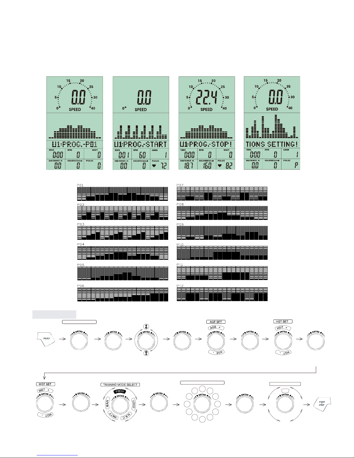
FIGURE 21 FIGURE 22 FIGURE 23 FIGURE 24
PROGRAM MODE
1. After enter PROGRAM mode, user and turn the UP/DOWN joggle wheel to select program
profile from P1 to P12, then press ENTER to confirm.
2. User can preset the TIME data then press START/STOP to start exercise.
3. After start training, TIME will be counted down. When the TIME is counted to 0, the
screen is flashing and the alarm is ringing. User can press any button to stop the alarm.
USER SELECT U1-U4
PRESS
RESET 3 SEC
TO RESET
CLOCKWISE OR
ANTI-CLOCKWISE
PROGRAM mode
PRESS
ENTER
CLOCKWISE OR
ANTI-CLOCKWISE
CLOCKWISE OR
ANTI-CLOCKWISE
PRESS
ENTER
PRESS
ENTER
CLOCKWISE OR
ANTI-CLOCKWISE
CLOCKWISE OR
ANTI-CLOCKWISE
PRESS
ENTER CLOCKWISE OR
ANTI-CLOCKWISE
PRESS
ENTER
PRESS
ENTER
FUNCTION SELECT
T
I
M
E
CLOCKWISE OR
ANTI-CLOCKWISE
PRESS
ENTER
PROGRAM SELECT P1 to P12
P1 P2
P3
P4
P5
P7 P6
P8
P9
P10
P11
P12
CLOCKWISE OR
ANTI-CLOCKWISE

to 0, the screen is flashing and the alarm is ringing. User can press any button to stop the
alarm.
FIGURE 25 FIGURE 26 FIGURE 27 FIGURE 28
FIGURE 29
USER PROGRAM
1. After enter USER PROGRAM mode, the first column of the profile is blinking (FIGURE 25).
User may turn the joggle wheel to adjust the resistance level (FIGURE 26) to create his /
her own profile.
2. After setting (from column 1 to column 20), user may hold on pressing MODE button for 2
seconds to quit profile setting and enter TIME setting.
3. While making the profile setting, user can press RESET and return to the menu.
4. After start training (FIGURE 27~29), TIME will be counted down. When TIME is counted
USER SELECT U1-U4
PRESS
RESET 3 SEC
TO RESET
CLOCKWISE OR
ANTI-CLOCKWISE
USER mode
PRESS
ENTER
CLOCKWISE OR
ANTI-CLOCKWISE
CLOCKWISE OR
ANTI-CLOCKWISE
PRESS
ENTER
PRESS
ENTER
CLOCKWISE OR
ANTI-CLOCKWISE
CLOCKWISE OR
ANTI-CLOCKWISE
PRESS
ENTER CLOCKWISE OR
ANTI-CLOCKWISE
PRESS
ENTER
PRESS
ENTER
FUNCTION SELECT
T
I
M
E
CLOCKWISE OR
ANTI-CLOCKWISE
PRESS
ENTER
Repeating these opeartion till completing the setting of 20 ranges
CLOCKWISE OR
ANTI-CLOCKWISE
Hold on pressing for 2 seconds
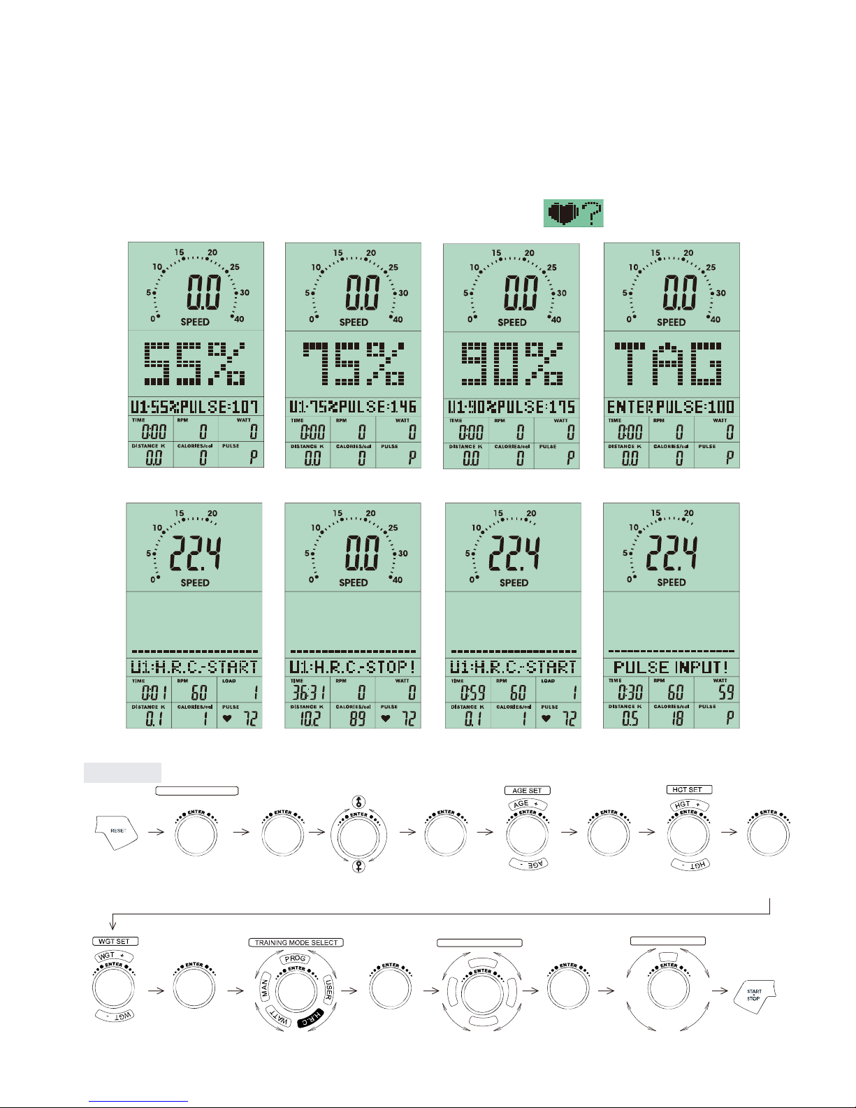
FIGURE 29 FIGURE 30 FIGURE 31 FIGURE 32
FIGURE 33 FIGURE 34 FIGURE 35 FIGURE 36
USER SELECT U1-U4
PRESS
RESET 3 SEC
TO RESET
CLOCKWISE OR
ANTI-CLOCKWISE
H.R.C. mode
PRESS
ENTER
CLOCKWISE OR
ANTI-CLOCKWISE
CLOCKWISE OR
ANTI-CLOCKWISE
PRESS
ENTER
PRESS
ENTER
CLOCKWISE OR
ANTI-CLOCKWISE
CLOCKWISE OR
ANTI-CLOCKWISE
PRESS
ENTER CLOCKWISE OR
ANTI-CLOCKWISE
PRESS
ENTER
PRESS
ENTER
FUNCTION SELECT
T
I
M
E
CLOCKWISE OR
ANTI-CLOCKWISE
PRESS
ENTER
TRAINING MODE SELECT
.
R
C
G
A
T
%
0
5
%
5
7
%
0
9
CLOCKWISE OR
ANTI-CLOCKWISE
HEART RATE CONTROL
1. After enter HEART RATE CONTROL mode, the screen will show heart rate percentage 55%,
75%, 90% and TARGET. User may select heart rate percentage by turning UP/ DOWN
joggle wheel for training.
2. User can preset the TIME data then press START/ STOP to start exercise.
3. After start training, TIME will be counted down. When the TIME is counted to 0, the
screen is flashing and the alarm is ringing. User can press any button to stop the alarm.
If there is no HR input for 5 seconds, LCD will display until HR signal input.
Table of contents
Other Sportop Elliptical Trainer manuals

Sportop
Sportop E80 Operation manual

Sportop
Sportop E 7000P Operation manual

Sportop
Sportop E7000P PLUS Operation manual

Sportop
Sportop E-860P Operation manual

Sportop
Sportop VST60 Operation manual

Sportop
Sportop E770 User manual

Sportop
Sportop RO 700 User manual

Sportop
Sportop E 8000P Operation manual

Sportop
Sportop E 8000P Operation manual

Sportop
Sportop E160 Operation manual

Popular Elliptical Trainer manuals by other brands


Gold's Gym
Gold's Gym Stride Trainer 410 user manual

Weslo
Weslo MOMENTUM 730 ELLIPTICAL EXERCISER... user manual

NordicTrack
NordicTrack Audiostrider NTEL7706.0 user manual

Matrix
Matrix G7-S77-02 Service manual

Insportline
Insportline inCondi ET520i user manual

BH FITNESS
BH FITNESS G2336B Instructions for assembly and use


