Sportop RO 700 User manual

POLYFOAM(1)
Warning:
POLYFOAM(2)
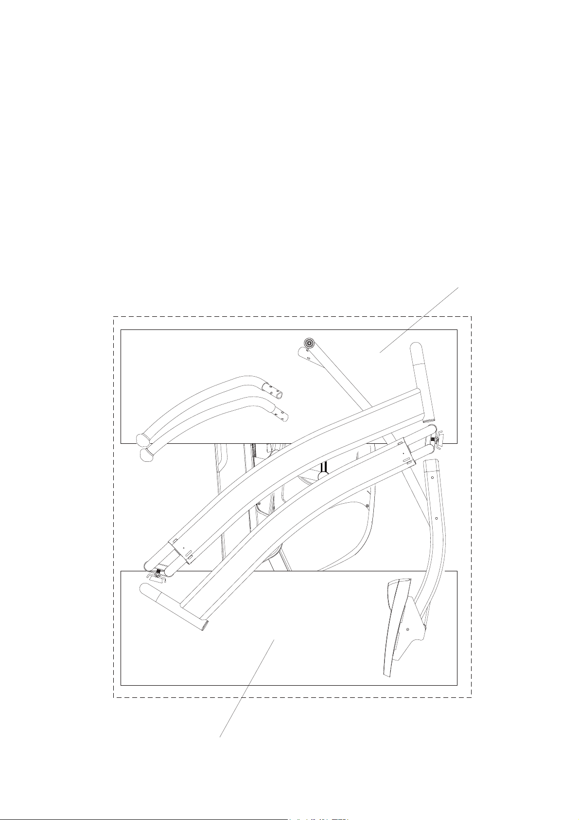
Unpacking Caution:
A. Lay the box down flat so that the lid is able to be lifted. Unpack the handle bars, side supporting
tubes, pedal supporting tube and owners manual. Remove the top polyfoam pieces #1 & #2 and
finish up packing the console, console supporting tube, central supporting tube, pedal supporting
tube, and hardware bag, leaving the main frame(A) and bottom polyfoam pieces #3 & #4 inside
the box until instructed to remove them.
B. Note: FOR SAFETY REASONS, DO NOT turn the pedal locking feature knob to the unlock position
until instructed to do so at the end of the assembly.
2#465.+56
- 1 -
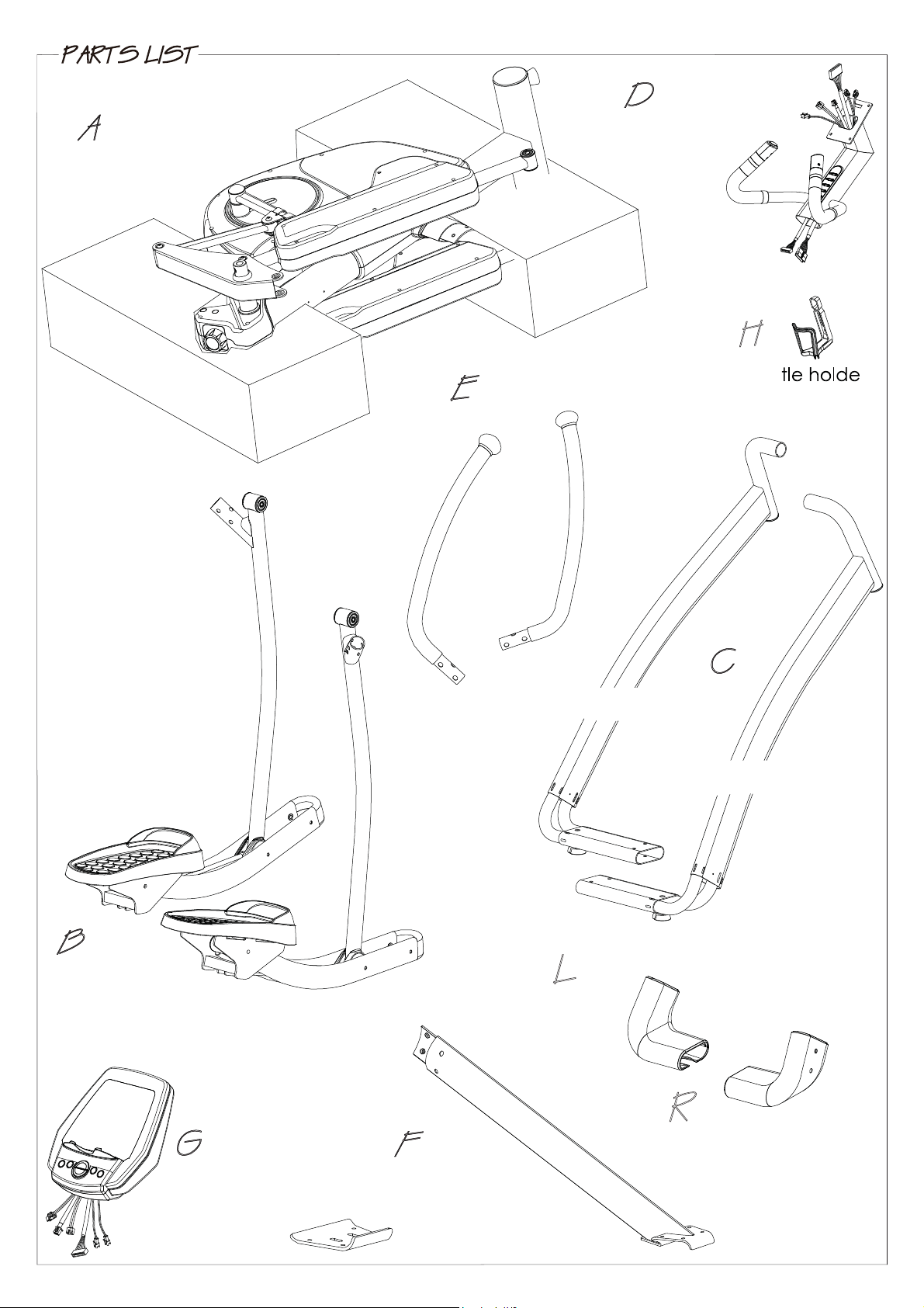
Main frame
B1 Pedal supporting
tube (L)
B2 Pedal supporting
tube (R)
Console
Console supporting
tube
Bot r
E1 Handle bar (L)
E2 Handle bar (R)
F1 Central
supporting tube
C2 Side connecting tube (R)
C1 Side connecting
tube (L)
F2 Iron bracket
Side tube cover set
Side tube cover set

2#465.+56
(J6) Screw M8X20
(J4) Screw M8X55
(J10) Screw M12X109
(J7) Screw M12X73
(J13) Screw M8X16
(J9) Nut M12
(J2) Screw M4X16 (J3) Screw M4X6
(J14) Screw M5
(J8) Washer M12
(J5) Washer M8
4m/m #19
6m/m*2
5m/m
- 2 -
- 3 -
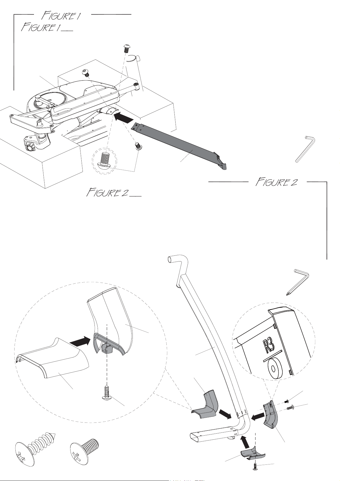
CENTRAL SUPPORTING TUBE (F1) ASSEMBLY
Step 1. Remove the two preassembled screws (J1) from the
main frame (A) and two screws (J1) from the central
supporting tube (F1).
Step 2. Assemble the central supporting tube (F1) onto
the main frame (A) use the previously removed
screws (J1) to join them.
SIDE TUBE COVER SETS (L+R) ASSEMBLY
Step 1. Connect the right side tube cover (R2) onto the cover (R1) and secure by screw (J2).
Step 2. Follow the step 2-1 to 2-4 to assemble the side tube cover sets.
2-1. Connect the covers (R1 & R2) onto the right side connecting tube (C2).
2-2. Connect the cover (R3) onto the tube (C2).
2-3. Connect the cover (R4) onto the tube (C2).
2-4. Secure the cover set by screw (J3) first then two screws (J2) as the picture shown.
Step 3. Repeat the previous same steps for
the left side tube cover set (L) assembly.
USE TOOL:6m/m
F1
J1
A
NOTE: Only hand tighten the screws (J1)
until assembly is fully completed
in “Figure 4”.
Step 1.
R1
R2
R1 & R2
R3
R4
J2 J3 J2
J2 J2
J3
2-1.
2-2.
2-3.
USE TOOL:4m/m
(Phillips Screw Driver)
C2

-4-
Step 1. Equip the left side connecting tube (C1) onto
the main frame (A).
Step 2. Secure it by using the screw (J6) on the top and the
two screws (J4), two washers (J5) with the iron
bracket (F2) on the bottom as the right side
tube (C2) in “Figure 3”.
Step 3. Now you can tighten all the screws (J1, J4,
and J6) in “Figure 1” to “Figure 4”.
Note: Make sure the central supporting tube
assembled in a position parallel with
the main frame tube, to avoid the
pedals hit central supporting tube.
LEFT SIDE CONNECTING TUBE ASSEMBLY
USE TOOL:6m/m
RIGHT SIDE CONNECTING TUBE ASSEMBLY
Step 1. As shown in Views (A & B) Assemble the right side connecting tube (C2)
assembly to the machine.
Step 2. As shown in View (A) Assemble the tube (C2) assembly onto the upper
main frame. Use one screw (J6) to join the tube to the frame.
Step 3. As shown in View (B) Use two screws (J4), two washers (J5) and the iron
bracket (F2) to join the tube to the frame on the bottom.
Note: Only hand tighten the screws (J4 & J6) until assembly is fully completed
in “Figure 4”.
USE TOOL:6m/m
VIEW A
J6
C2
VIEW B
J4
J4
F2
C2 C2
Step 4. Raise the main frame (A) by 2 people
and then remove the Polyfoams as
the diagram shown.
AJ5
J5
J6
J4
J5
C1
A

-5-
PEDAL SUPPORTING TUBE ASSEMBLY
Step 1. As shown in View (C) Connect the right
pedal supporting tube (B2) to main
frame (A). Use the tools provided to
tighten screw (J7), washer (J8) and nut (J9).
Step 2. As shown in View (D) Connect and align the
right lower pedal supporting tube (B5) to the front pedal
supporting tube on the main frame (A). Use the tools
provided to tighten screw (J10), washer (J8) and
nut(J9).
Step 3. As shown in View (E) Tighten the preinstalled
screw (J10) and nut (J9) firm.
Step 4. Repeat the previous same steps for the
left pedal supporting tube (B1) assembly.
VIEW C
VIEW D
A
J8
J9
J7
B2
J9 J10
B5
J8
VIEW E
USE TOOL:6m/m
#19
HANDLE BAR ASSEMBLY
Step 1. Remove the six preinstalled screws (J11 & J12) from
the left handle bar (E1) .
Step 2. As shown in View (F) Assemble the left handle
bar (E1) into the main frame (A).
Using the two 6mm allen wrench to
tighten the six screws (J11&J12).
Note: Make sure to tighten handle bar
screws tight to prevent a clicking noise
in the handle bars. Wiggle the handle bars
to help seed screws in place and then retighten.
Step 3. Repeat the same steps for the right handle bar (E2).
A
E1
J11*6
J12*6
VIEW F
J12
J12
J12*6
J11*6
J12
J11
USE TOOL:6m/m*2

-6-
CONSOLE ASSEMBLY
Stpe 1. Remove the four screws (G1) from the back of
console (G).
Step 2. Connect console wires (D1,D3,G3,G4) and heart rate
wires (D4) to the console. Heart rate wires can be
interchangeable.
Note : Make sure the wires are connected together properly.
Push and store excess wires back into the console
supporting tube (D). Be careful not to pinch the
wires while assembling the console.
Step 3. Hand tighten the four screws (G1) first, and
then use the screw driver to tighten the
four screws (G1) to secure the console (G)
onto the console supporting tube (D).
Step 4. Adjust the levelers on the bottom rear of
supporting tubes to stabilize the machine.
USE TOOL:4m/m
(Phillips Screw Driver)
CONSOLE SUPPORTING TUBE
AND BOTTLE HOLDER ASSEMBLY
Step 1. Connect wires (D1 & D2) from the console
supporting tube (D) to wires (A1 & A2) from the
main frame (A).
Step 2. Slide the console supporting tube (D) onto the
main frame (A). Store excess wires into the tube.
If needed, loosen the preinstalled screw (J13)
slightly in the main frame (A) to help slide console
supporting tube down or to help align holes for
the screws (J13).Be careful not to pinch the wires
while assembling the tube.
Step 3. Using the 5mm Allan wrench tighten the
four screws (J13) firm.
Note : Make sure that all wires are connected
together properly; all screws (J13) are tight
to prevent a loose console support tube.
Step 4. Use the two screws (J14) located in the
water bottle holder bag to join the water
bottle holder (H) to the main frame (A).
D
D2 D1
A2 A1
A
H
J14
VIEW G
J13
USE TOOL:4m/m
5m/m
J13
J13
J13
G
G1
D
D1
D3 D4
G4
G3

-7-
POWER CORD ASSEMBLY
Attach the power cord jacket into the power socket on
the main frame before plugging the power cord plug into
the wall outlet.
Turn the AC power switch on.
Flip the ON/OFF switch to the ON position.
"0" sign is for OFF; "I" sign is for ON.
Note: The Overload switch is for device over loading
protection. Overload switch will pop-up when the
machine is electrically over loaded. Turn off the AC
power switch and turn it back on to restart
the machine.
FOR YOUR SAFETY, this machine is equipped with a pedal locking feature. The
pedals can be manually disabled so that it cannot be moved accidently. Turn the knob left
or right one click until you see the arrow point to the “LOCK OR UNLOCK” symbol. While the
machine is in idle; NEVER in motion, turn the knob (A3) to “LOCK” to disable the pedals or turn
the knob to “UNLOCK” to release the pedals. The machine should always be at the “LOCK”
position when NOT in use. It would prevent the children or user from being hurt.
WARNING: FOR YOUR SAFETY, never lock the pedal locking feature
while the machine is in motion, only when it is at a full
complete stop it is safe to move the knob.
Pedal Locking Feature
A3
-8-
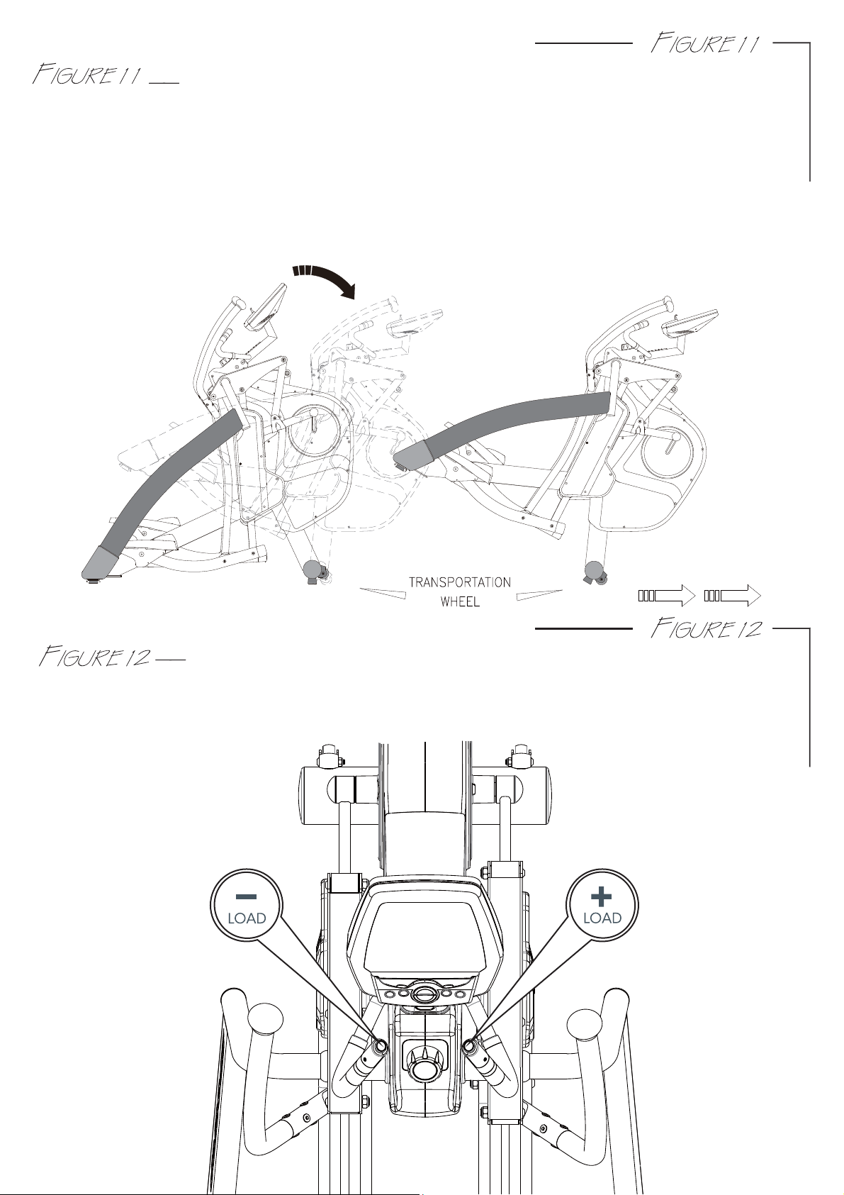
If the machine needs to be transported to a different location, make sure that the pedal
lock knob is at “LOCK” position. Lift up both sides of the rear supporting tubes until the front
transportation wheels are touching the ground. You may now move the machine to the
desired location. After the move, gently set the machine down at its new location and adjust
the levelers on the bottom rear of supporting tubes to stabilize the machine if needed.
WARNING: Never attempt to lift the machine by yourself, ask for additional help if needed
and never attempt to lift the machine if you have any medical issues.
HOW TO TRANSPORT THE MACHINE
When the console is working out, you may press the toggle buttons on the small handlebar
to slightly adjust the resistance: press “+LOAD” button on the right side to increase
resistance; or press “-LOAD” button on the left side to decrease resistance.
HOW TO USE TOGGLE SWITCH TO ADJUST THE RESISTANCE

Depending on the personal demand to change the stride in different distance 18”, 20”, 22”,
24”, and 26” as the LED sensor displayed. There are 5 stride control quick keys, press one of
the 18” – 26” keys to adjust to desired stride length. You may change the stride length anytime
during a workout. Selected stride length will be shown on the stride length blue LED sensor.
A user will want to adjust the stride length for a few reasons. First reason is for height, a user at
or below 5’5” may feel more comfortable with 18” to 22” stride and a user at or above 5’5”
may feel more comfortable with 22” to 26” stride to compensate for their normal step/walking
stride. In addition, as a user increases speed, they may need to adjust the stride length to
compensate for his or her normal jog/run stride. Next reason why a user may want to adjust
the stride length during a workout is to work different muscle groups; a shorter stride length will
work different muscles in your legs and body than a longer stride length. An 18” stride can be
comparable to a shorter stepping motion and 26” stride can be compared to a lunge workout
without the high impact as the same workouts performed on a flat surface.
While working out, adjusting resistance and or squatting while holding on to the handlebars
can also help to isolate these muscles further.
Note: There is no right or wrong stride length for any user, choose any length according to
what feels most comfortable.
Note: Always consult a local personal trainer for more in depth work out details.
Note: When the stride motor is activated, you will hear the motor unlock and adjust, once
motor is to desired stride, the motor will click to lock position.
-9-
HOW TO ADJUST STRIDE BY INCLINE MOTORIZED
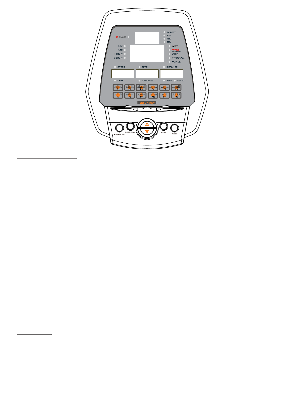
FUNCTION BUTTONS:
MODE To confirm all setting values.
RESET To reset all setting values.
Hold on pressing for 2 seconds, monitor will resume to power-up mode.
START/STOP To start or stop training.
When time count down to 0:00, the computer will stop automatically and beep for
8 seconds. Time will resume to pervious setting value.
When user stop training by themselves, the computer will remain all the setting
values and display heart rate chart
UP To make upward setting.
DOWN To make downward setting.
RECOVERY In stop or start mode, press the button wil start heart rate recovery status
measurement. Time will count down from 0:60.
P1 Swift to program profile 1.
P2 Swift to program profile 2.
P3 Swift to program profile 3.
P4 Swift to program profile 4.
P5 Swift to program profile 5.
P6 Swift to program profile 6.
P7 Swift to program profile 7.
P8 Swift to program profile 8.
P9 Swift to program profile 9.
P10 Swift to program profile 10.
P11 Swift to program profile 11.
P12 Swift to program profile 12.
FUNCTIONS:
TIME Count up – no preset target, time will count up from 0:00 to maximum 99:59
Count down – with preset target, time will count down from preset to 0.
SPEED Display training speed from 0.0 to maximum 99.9 km or ml.
RPM Display training rotation per minute
CALORIES Count up – no preset target, calories will count up from 0 to maximum 9990.
Count down – with preset target, calories will count down from preset to 0.
-10-
DISTANCE Count up – no preset target, distance will count down from 0.00 to 99.50.
Count down – with preset target, distance will count up from preset to 0.
PULSE The monitor will detect heart rage figures, when user hold on hand grip sensor
or wear chest belt. The hand grip is priority.
When the monitor cannot detect pulse signal, will display “P”.
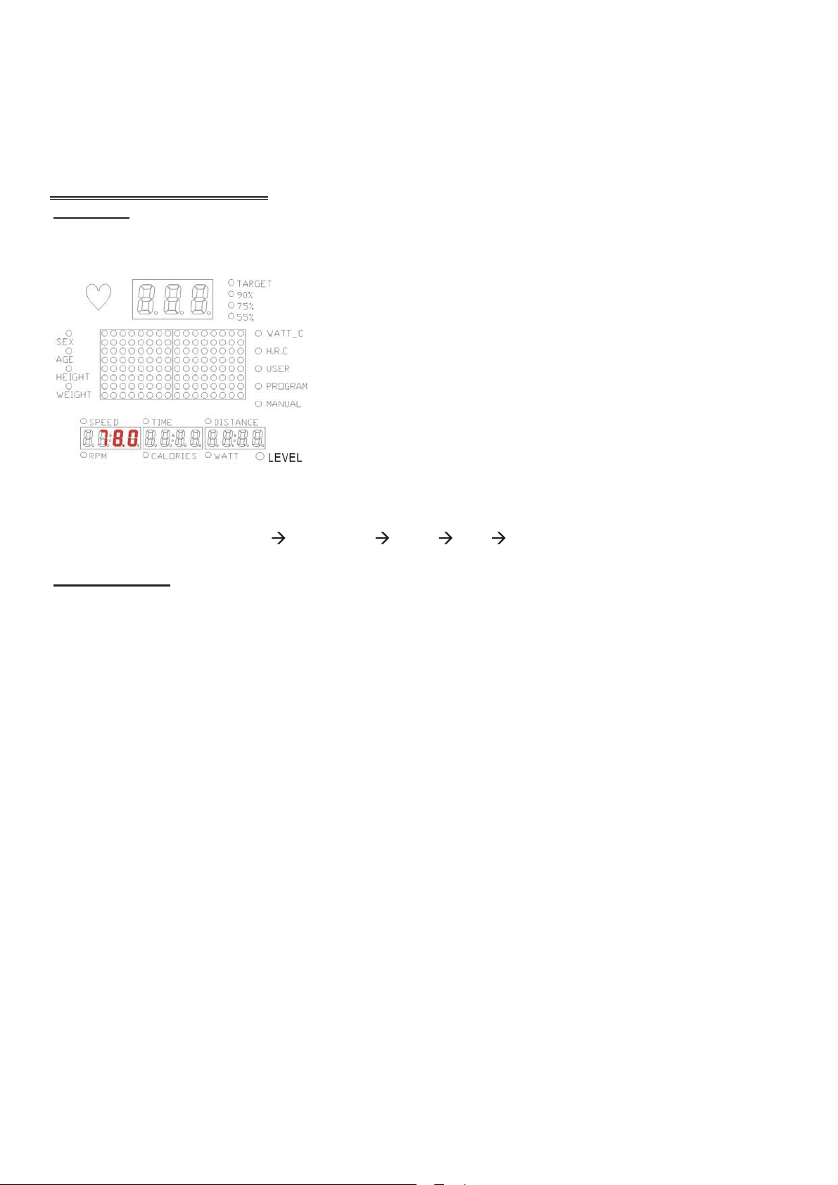
OPERATING PROCEDURE:
Power on
To connect power supply to the monitor, the monitor will display all segments with a long beep for
2seconds.
Programs with its corresponding LED will illuminated, user may press UP and DOWN to select
preferred program (MANUAL PROGRAM USER HRC WATT).
Training mode
1. Training mode selection:
1-1 Manual mode
User may preset their own resistance level from 1 to 16 by press UP or DOWN button.
The default resistance level is from row one. The press mode to confirm setting.
TIME : is blinking. You may press UP or DOWN button to set up target training time from
00:00 to 99:00. Press MODE to confirm setting.
DISTANCE : is blinking. You may press UP or DOWN button to set up target distance
from 0.00~99.59. Press MODE to confirm setting.
CALORIES : is blinking. You may press UP or DOWN button to set up target calories
from 0~9990. Press MODE to confirm setting.
PULSE : the monitor will detect user’s heart rate. Please hold on handgrip sensor or
wear chest belt when start exercise.
Press START button to start training:
The first column starts blinking and switch to the next column per preset time divided
into 16.Once the preset target data counting down to 0, the monitor will stop
automatically. You may press START button to start training again. Other preset data
will keep counting down from pervious data.
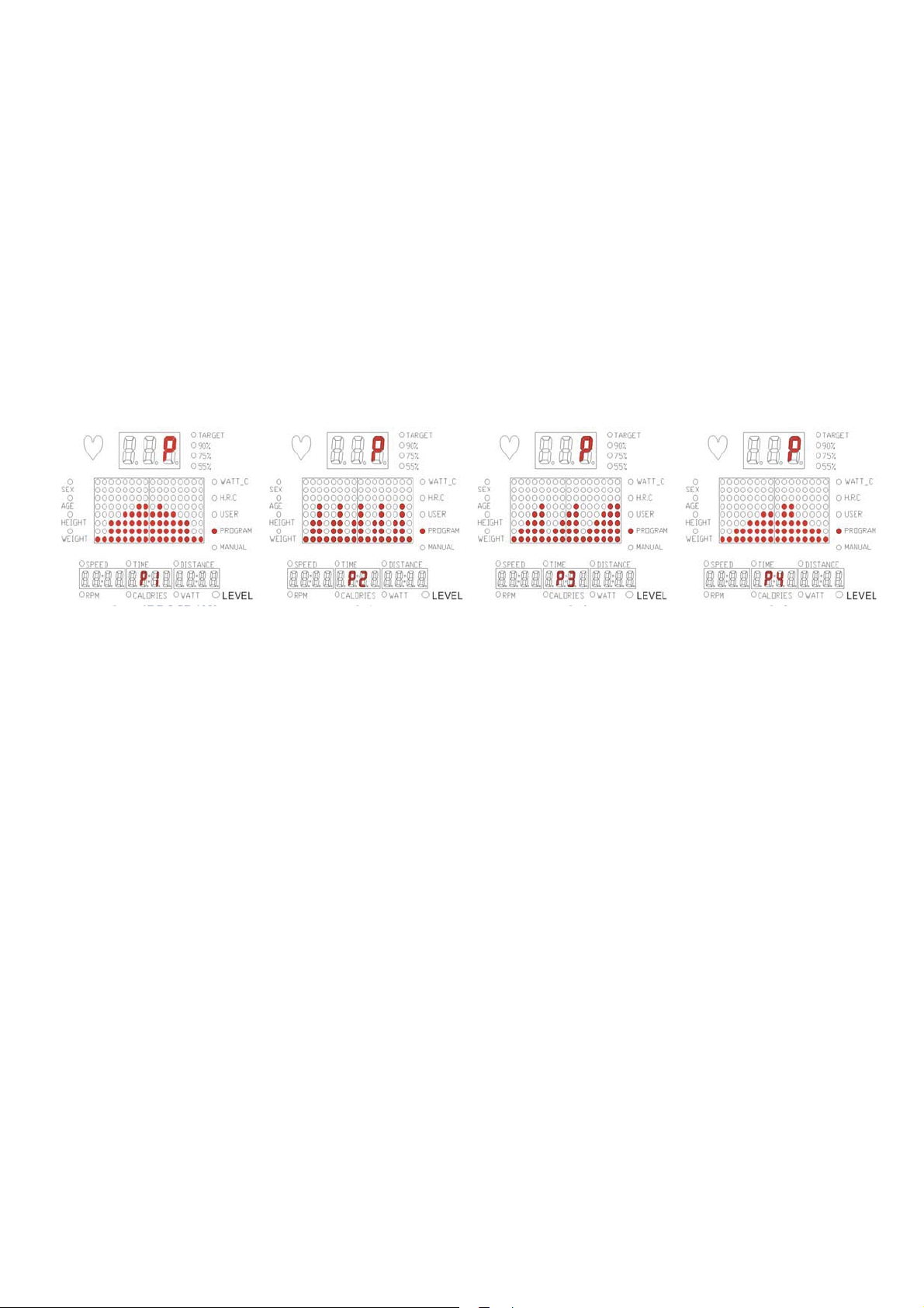
1-2 Program mode
There are 12 program profiles (P1~P12) for training selection. User may press program
buttons from P1 to P12 to swift to selected profiles in stop mode.
Or press UP or DOWN button to select each profiles you want and press MODE to
confirm. Then you may press UP or DOWN button to adjust the resistance level from 1
to 16.
-11-
TIME : is blinking. You may press UP or DOWN button to set up target training time from
00:00 to 99:00. Press MODE to confirm setting.
DISTANCE : is blinking. You may press UP or DOWN button to set up target distance
from 0.00~99.59. Press MODE to confirm setting.
CALORIES : is blinking. You may press UP or DOWN button to set up target calories
from 0~9990. Press MODE to confirm setting.
PULSE : the monitor will detect user’s heart rate. Please hold on handgrip sensor or
wear chest belt when start exercise.
Press START button to start training:
The first column starts blinking and switch to the next column per preset time divided
into 16.Once the preset target data counting down to 0, the monitor will stop
automatically. You may press START button to start training again. Other preset data
will keep counting down from pervious data.
1-3 User profile mode
User my create their own profile in this mode. The first column of the profile will start
blinking, then you may press UP or DOWN button to adjust resistance level of each
column and press MODE to confirm. There are 16 columns for the profile.
TIME : is blinking. You may press UP or DOWN button to set up target training time from
00:00 to 99:00. Press MODE to confirm setting.
DISTANCE : is blinking. You may press UP or DOWN button to set up target distance
from 0.00~99.59. Press MODE to confirm setting.
CALORIES : is blinking. You may press UP or DOWN button to set up target calories
from 0~9990. Press MODE to confirm setting.
PULSE : the monitor will detect user’s heart rate. Please hold on handgrip sensor or
wear chest belt when start exercise.
Press START button to start training:
The first column starts blinking and switch to the next column per preset time divided
into 16.Once the preset target data counting down to 0, the monitor will stop
automatically. You may press START button to start training again. Other preset data
will keep counting down from pervious data.
1-4 WATT control mode
User may preset WATT value by press UP or DOWN button, with 5W increment and
press MODE to confirm.
TIME : is blinking. You may press UP or DOWN button to set up target training time from
00:00 to 99:00. Press MODE to confirm setting.
DISTANCE : is blinking. You may press UP or DOWN button to set up target distance
-12-

from 0.00~99.59. Press MODE to confirm setting.
CALORIES : is blinking. You may press UP or DOWN button to set up target calories
from 0~9990. Press MODE to confirm setting.
PULSE : the monitor will detect user’s heart rate. Please hold on handgrip sensor or
wear chest belt when start exercise.
Press START button to start training:
Screen display profile automatically according to the preset target watt datas, current
RPM and training speed. This profile is not available to be adjusted. It the training
speed is quick, resistance level will decreased. Otherwise, it will increase. The
adjustment is to maintain the preset watt for training.
1-5 H.R.C. mode
User may preset different target heart rate from 55%, 75%, 90% and Target by press UP
and DOWN button. And press MODE to confirm.
TIME : is blinking. You may press UP or DOWN button to set up target training time from
00:00 to 99:00. Press MODE to confirm setting.
DISTANCE : is blinking. You may press UP or DOWN button to set up target distance
from 0.00~99.59. Press MODE to confirm setting.
CALORIES : is blinking. You may press UP or DOWN button to set up target calories
from 0~9990. Press MODE to confirm setting.
PULSE : the monitor will detect user’s heart rate. Please hold on handgrip sensor or
wear chest belt when start exercise.
Press START button to start training:
The resistance level will adjust according you current heart rate. When it is lower than
preset target, the resistance level will increase one row every 30 seconds automatically.
On the contrary, the resistance level will decrease one row every 15 seconds until reach
first level. In level 1, if user’s hear rate still exceed more than 30 seconds, the monitor
will stop and start bi-bi-bi-bi-bi-bi to warm user.
NOTE:
1. The monitor display will shut off if the training is stop or not press any button for 4
minutes.
2. Error message: E2
When monitor appears this information, the control board connection is failed. This
message will disappear when the failure is fixed.
-13-
Table of contents
Other Sportop Elliptical Trainer manuals

Sportop
Sportop E450 Operation manual

Sportop
Sportop E 8000P Operation manual

Sportop
Sportop E770 User manual

Sportop
Sportop E7000P PLUS Operation manual

Sportop
Sportop E7000P PLUS Operation manual

Sportop
Sportop E160 Operation manual

Sportop
Sportop E 8000P Operation manual

Sportop
Sportop E 7000P Operation manual

Sportop
Sportop E80 Operation manual

Sportop
Sportop E-860P Operation manual


