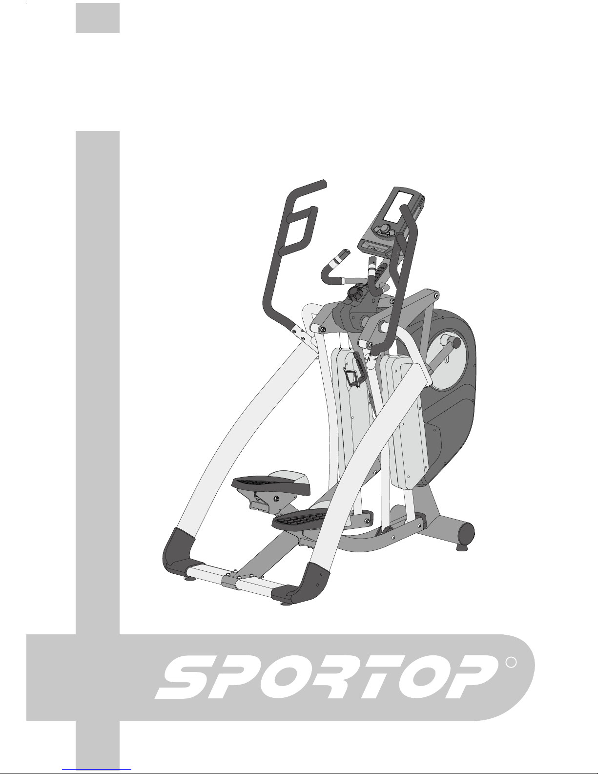
Sportop E770 User manual
R
CHANGEABLE
STRIDE ELLIPTICAL
Owner’s Operating Manual ENGLISH
MODEL:E770

POLYFOAM(1)
Warning:
POLYFOAM(2)
Unpacking Caution:
A. Lay the box down flat so that the lid is able to be lifted. Unpack the handle bars, side supporting
tubes, pedal supporting tube and owners manual. Remove the top polyfoam pieces #1 & #2 and
finish up packing the console, console supporting tube, central supporting tube, pedal supporting
tube, and hardware bag, leaving the main frame(A) and bottom polyfoam pieces #3 & #4 inside
the box until instructed to remove them.
B. Note: FOR SAFETY REASONS, DO NOT turn the pedal locking feature knob to the unlock position
until instructed to do so at the end of the assembly.
2#465.+56
- 1 -
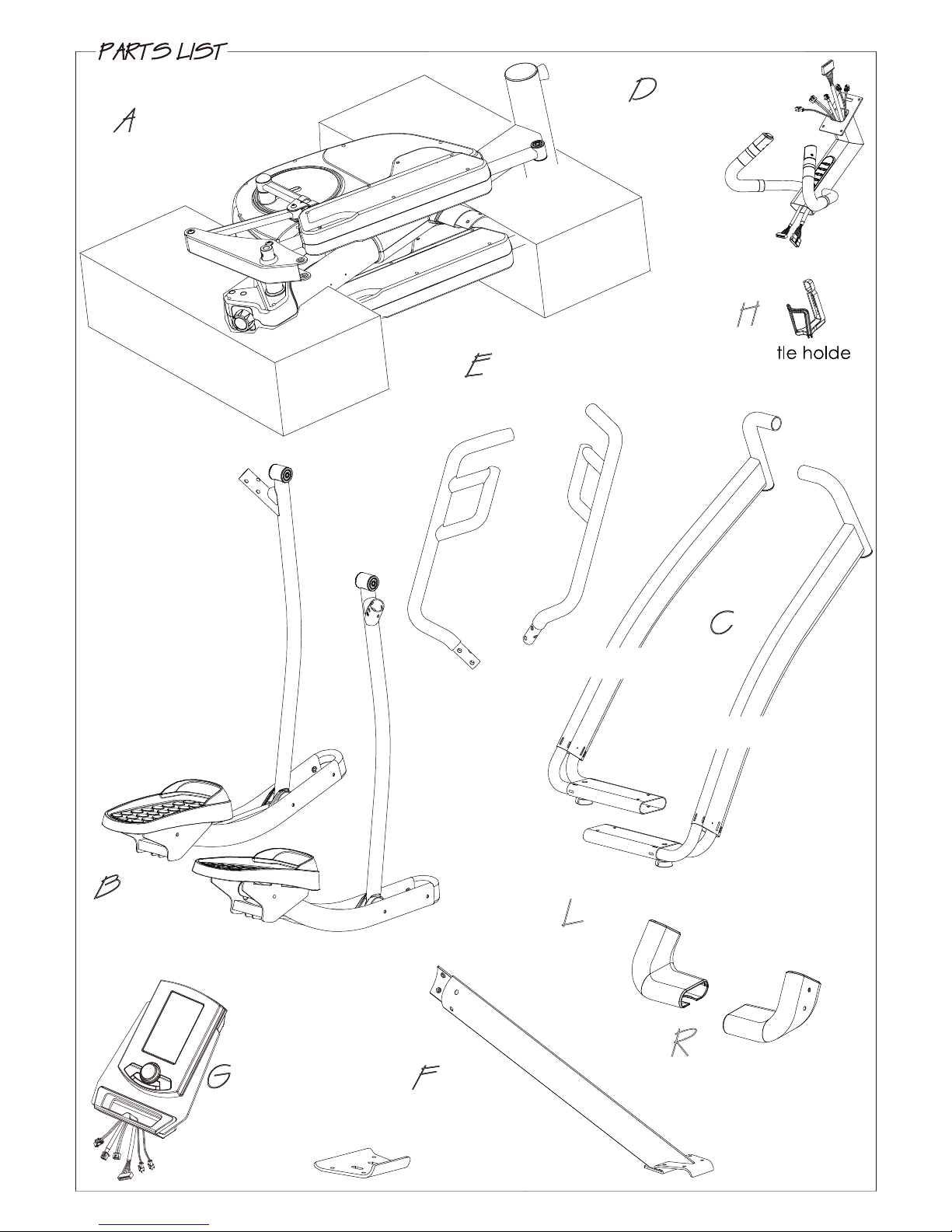
Main frame
B1 Pedal supporting
tube (L)
B2 Pedal supporting
tube (R)
Console
Console supporting
tube
Bot r
E1 Handle bar (L)
E2 Handle bar (R)
F1 Central
supporting tube
C2 Side connecting tube (R)
C1 Side connecting
tube (L)
F2 Iron bracket
Side tube cover set
Side tube cover set
2#465.+56
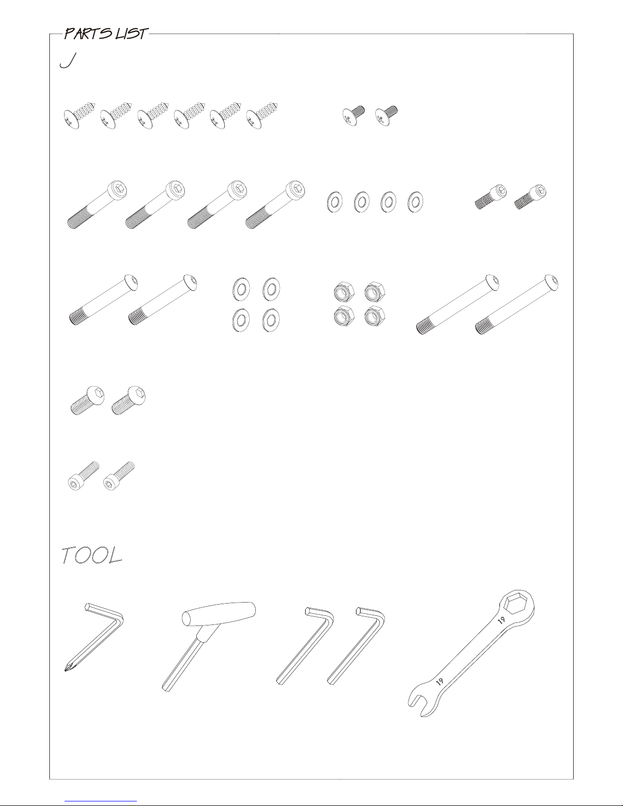
(J6) Screw M8X20
(J4) Screw M8X55
(J10) Screw M12X109
(J7) Screw M12X73
(J13) Screw M8X16
(J9) Nut M12
(J2) Screw M4X16 (J3) Screw M4X6
(J14) Screw M5
(J8) Washer M12
(J5) Washer M8
4m/m #19
6m/m*2
5m/m
- 2 -

- 3 -
CENTRAL SUPPORTING TUBE (F1) ASSEMBLY
Step 1. Remove the two preassembled screws (J1) from the
main frame (A) and two screws (J1) from the central
supporting tube (F1).
Step 2. Assemble the central supporting tube (F1) onto
the main frame (A) use the previously removed
screws (J1) to join them.
SIDE TUBE COVER SETS (L+R) ASSEMBLY
Step 1. Connect the right side tube cover (R2) onto the cover (R1) and secure by screw (J2).
Step 2. Follow the step 2-1 to 2-4 to assemble the side tube cover sets.
2-1. Connect the covers (R1 & R2) onto the right side connecting tube (C2).
2-2. Connect the cover (R3) onto the tube (C2).
2-3. Connect the cover (R4) onto the tube (C2).
2-4. Secure the cover set by screw (J3) first then two screws (J2) as the picture shown.
Step 3. Repeat the previous same steps for
the left side tube cover set (L) assembly.
USE TOOL:6m/m
F1
J1
A
NOTE: Only hand tighten the screws (J1)
until assembly is fully completed
in “Figure 4”.
Step 1.
R1
R2
R1 & R2
R3
R4
J2 J3 J2
J2 J2
J3
2-1.
2-2.
2-3.
USE TOOL:4m/m
(Phillips Screw Driver)
C2
-4-
Step 1. Equip the left side connecting tube (C1) onto
the main frame (A).
Step 2. Secure it by using the screw (J6) on the top and the
two screws (J4), two washers (J5) with the iron
bracket (F2) on the bottom as the right side
tube (C2) in “Figure 3”.
Step 3. Now you can tighten all the screws (J1, J4,
and J6) in “Figure 1” to “Figure 4”.
Note: Make sure the central supporting tube
assembled in a position parallel with
the main frame tube, to avoid the
pedals hit central supporting tube.
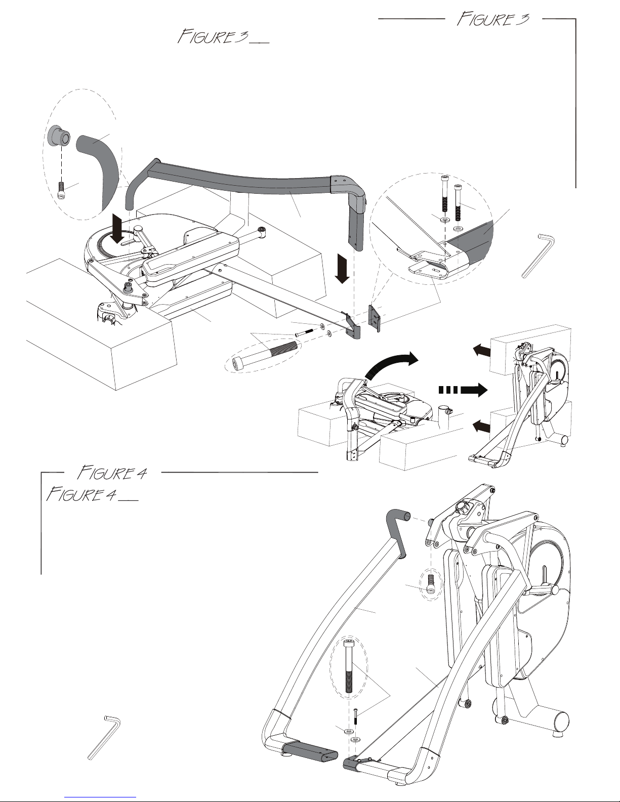
LEFT SIDE CONNECTING TUBE ASSEMBLY
USE TOOL:6m/m
RIGHT SIDE CONNECTING TUBE ASSEMBLY
Step 1. As shown in Views (A & B) Assemble the right side connecting tube (C2)
assembly to the machine.
Step 2. As shown in View (A) Assemble the tube (C2) assembly onto the upper
main frame. Use one screw (J6) to join the tube to the frame.
Step 3. As shown in View (B) Use two screws (J4), two washers (J5) and the iron
bracket (F2) to join the tube to the frame on the bottom.
Note: Only hand tighten the screws (J4 & J6) until assembly is fully completed
in “Figure 4”.
USE TOOL:6m/m
VIEW A
J6
C2
VIEW B
J4
J4
F2
C2 C2
Step 4. Raise the main frame (A) by 2 people
and then remove the Polyfoams as
the diagram shown.
AJ5
J5
J6
J4
J5
C1
A
-5-
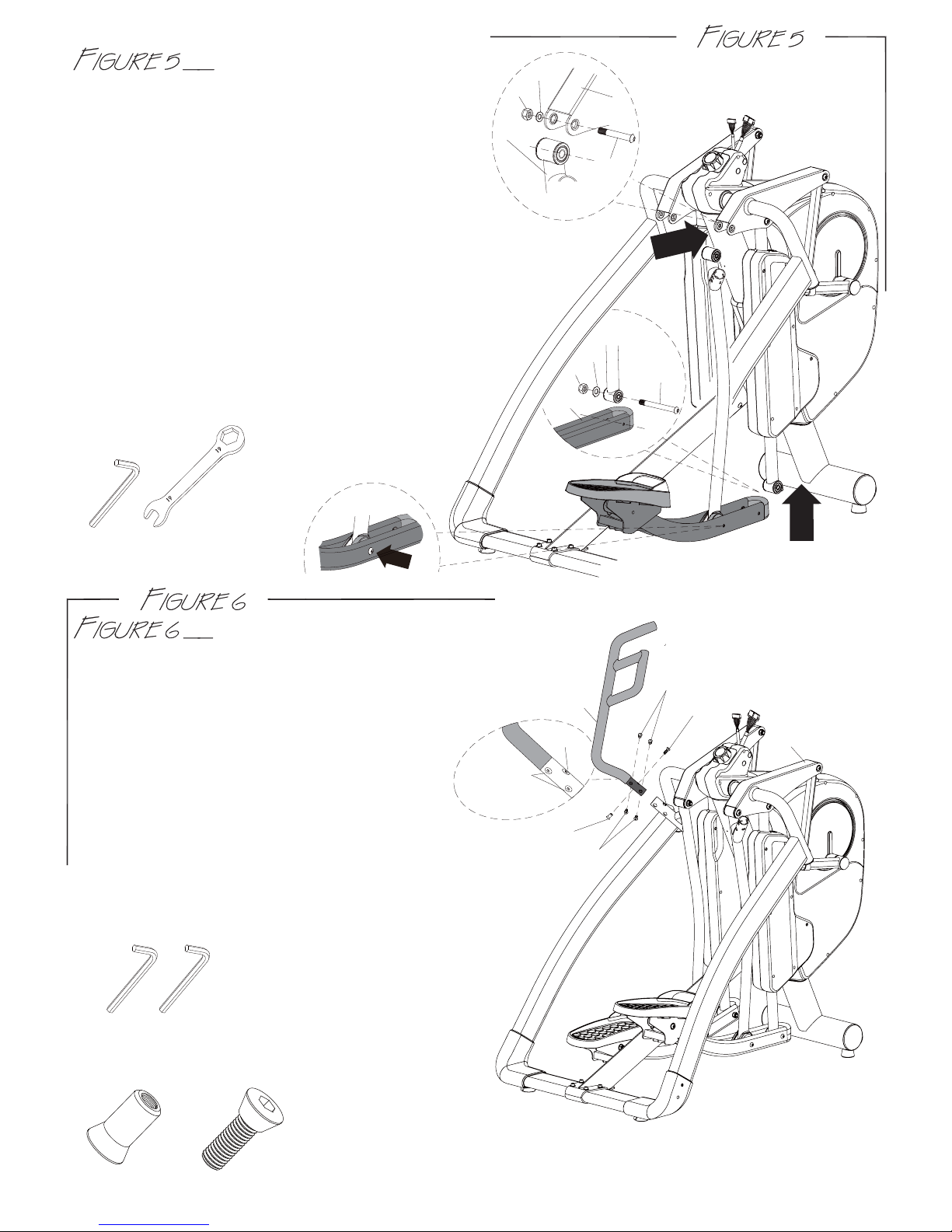
PEDAL SUPPORTING TUBE ASSEMBLY
Step 1. As shown in View (C) Connect the right
pedal supporting tube (B2) to main
frame (A). Use the tools provided to
tighten screw (J7), washer (J8) and nut (J9).
Step 2. As shown in View (D) Connect and align the
right lower pedal supporting tube (B5) to the front pedal
supporting tube on the main frame (A). Use the tools
provided to tighten screw (J10), washer (J8) and
nut(J9).
Step 3. As shown in View (E) Tighten the preinstalled
screw (J10) and nut (J9) firm.
Step 4. Repeat the previous same steps for the
left pedal supporting tube (B1) assembly.
VIEW C
VIEW D
A
J8
J9
J7
B2
J9 J10
B5
J8
VIEW E
USE TOOL:6m/m
#19
HANDLE BAR ASSEMBLY
Step 1. Remove the six preinstalled screws (J11 & J12) from
the left handle bar (E1) .
Step 2. As shown in View (F) Assemble the left handle
bar (E1) into the main frame (A).
Using the two 6mm allen wrench to
tighten the six screws (J11&J12).
Note: Make sure to tighten handle bar
screws tight to prevent a clicking noise
in the handle bars. Wiggle the handle bars
to help seed screws in place and then retighten.
Step 3. Repeat the same steps for the right handle bar (E2).
A
E1
J11*6
J12*6
VIEW F
J12
J12
J12*6
J11*6
J12
J11
USE TOOL:6m/m*2
-6-
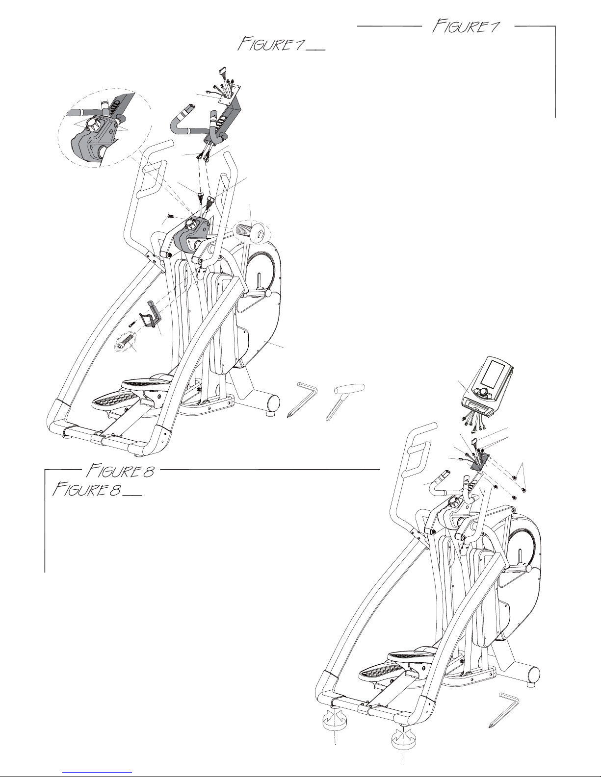
CONSOLE ASSEMBLY
Stpe 1. Remove the four screws (G1) from the back of
console (G).
Step 2. Connect console wires (D1,D3,G3,G4) and heart rate
wires (D4) to the console. Heart rate wires can be
interchangeable.
Note : Make sure the wires are connected together properly.
Push and store excess wires back into the console
supporting tube (D). Be careful not to pinch the
wires while assembling the console.
Step 3. Hand tighten the four screws (G1) first, and
then use the screw driver to tighten the
four screws (G1) to secure the console (G)
onto the console supporting tube (D).
Step 4. Adjust the levelers on the bottom rear of
supporting tubes to stabilize the machine.
USE TOOL:4m/m
(Phillips Screw Driver)
CONSOLE SUPPORTING TUBE
AND BOTTLE HOLDER ASSEMBLY
Step 1. Connect wires (D1 & D2) from the console
supporting tube (D) to wires (A1 & A2) from the
main frame (A).
Step 2. Slide the console supporting tube (D) onto the
main frame (A). Store excess wires into the tube.
If needed, loosen the preinstalled screw (J13)
slightly in the main frame (A) to help slide console
supporting tube down or to help align holes for
the screws (J13).Be careful not to pinch the wires
while assembling the tube.
Step 3. Using the 5mm Allan wrench tighten the
four screws (J13) firm.
Note : Make sure that all wires are connected
together properly; all screws (J13) are tight
to prevent a loose console support tube.
Step 4. Use the two screws (J14) located in the
water bottle holder bag to join the water
bottle holder (H) to the main frame (A).
USE TOOL:4m/m
5m/m
D1
A2 A1
A
H
J14
J13
J13
J13
J13
D
D2
VIEW G
G
G1
D
D1
D3
D4
G4
G3
-7-
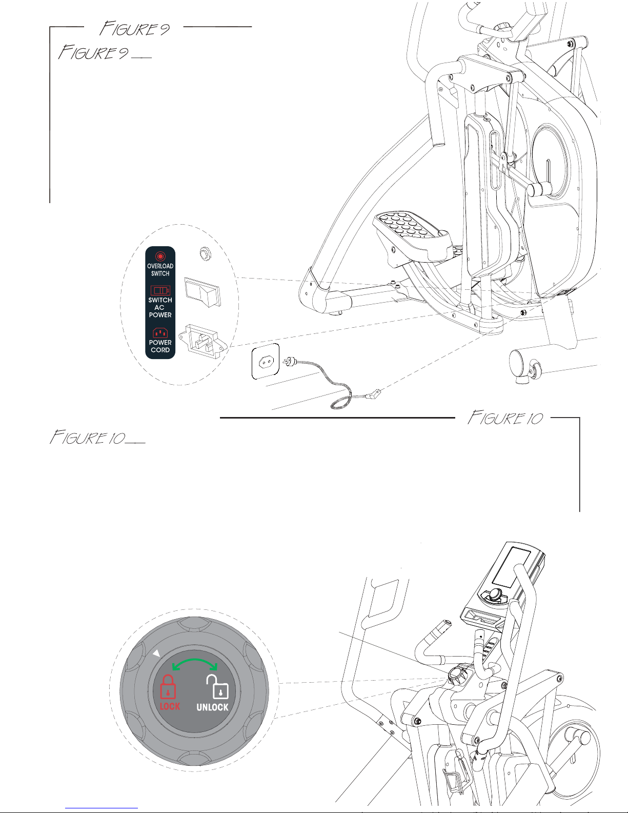
POWER CORD ASSEMBLY
Attach the power cord jacket into the power socket on
the main frame before plugging the power cord plug into
the wall outlet.
Turn the AC power switch on.
Flip the ON/OFF switch to the ON position.
"0" sign is for OFF; "I" sign is for ON.
Note: The Overload switch is for device over loading
protection. Overload switch will pop-up when the
machine is electrically over loaded. Turn off the AC
power switch and turn it back on to restart
the machine.
FOR YOUR SAFETY, this machine is equipped with a pedal locking feature. The
pedals can be manually disabled so that it cannot be moved accidently. Turn the knob left
or right one click until you see the arrow point to the “LOCK OR UNLOCK” symbol. While the
machine is in idle; NEVER in motion, turn the knob (A3) to “LOCK” to disable the pedals or turn
the knob to “UNLOCK” to release the pedals. The machine should always be at the “LOCK”
position when NOT in use. It would prevent the children or user from being hurt.
WARNING: FOR YOUR SAFETY, never lock the pedal locking feature
while the machine is in motion, only when it is at a full
complete stop it is safe to move the knob.
Pedal Locking Feature
A
3

If the machine needs to be transported to a different location, make sure that the pedal
lock knob is at “LOCK” position. Lift up both sides of the rear supporting tubes until the front
transportation wheels are touching the ground. You may now move the machine to the
desired location. After the move, gently set the machine down at its new location and adjust
the levelers on the bottom rear of supporting tubes to stabilize the machine if needed.
WARNING: Never attempt to lift the machine by yourself, ask for additional help if needed
and never attempt to lift the machine if you have any medical issues.
HOW TO TRANSPORT THE MACHINE
When the console is working out, you may press the toggle buttons on the small handlebar
to slightly adjust the resistance: press “+LOAD” button on the right side to increase
resistance; or press “-LOAD” button on the left side to decrease resistance.
HOW TO USE TOGGLE SWITCH TO ADJUST THE RESISTANCE
-8-
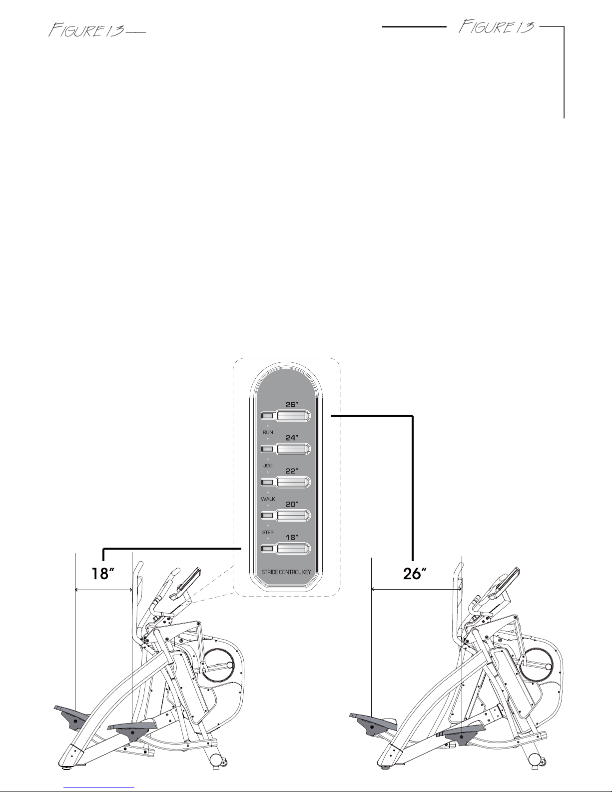
Depending on the personal demand to change the stride in different distance 18”, 20”, 22”,
24”, and 26” as the LED sensor displayed. There are 5 stride control quick keys, press one of
the 18” – 26” keys to adjust to desired stride length. You may change the stride length anytime
during a workout. Selected stride length will be shown on the stride length blue LED sensor.
A user will want to adjust the stride length for a few reasons. First reason is for height, a user at
or below 5’5” may feel more comfortable with 18” to 22” stride and a user at or above 5’5”
may feel more comfortable with 22” to 26” stride to compensate for their normal step/walking
stride. In addition, as a user increases speed, they may need to adjust the stride length to
compensate for his or her normal jog/run stride. Next reason why a user may want to adjust
the stride length during a workout is to work different muscle groups; a shorter stride length will
work different muscles in your legs and body than a longer stride length. An 18” stride can be
comparable to a shorter stepping motion and 26” stride can be compared to a lunge workout
without the high impact as the same workouts performed on a flat surface.
While working out, adjusting resistance and or squatting while holding on to the handlebars
can also help to isolate these muscles further.
Note: There is no right or wrong stride length for any user, choose any length according to
what feels most comfortable.
Note: Always consult a local personal trainer for more in depth work out details.
Note: When the stride motor is activated, you will hear the motor unlock and adjust, once
motor is to desired stride, the motor will click to lock position.
-9-
HOW TO ADJUST STRIDE BY INCLINE MOTORIZED
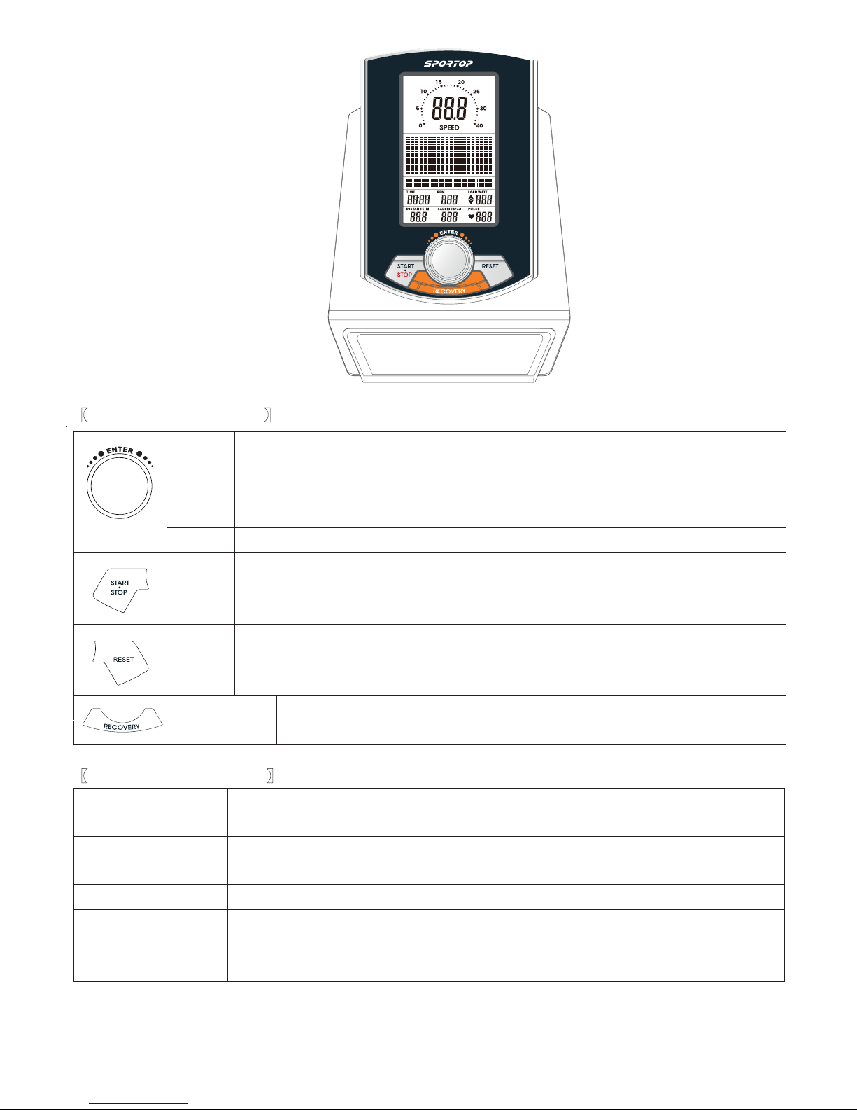
μBUTTON FUNCTIONSν
μDISPLAY FUNCTIONSν
TIME
T
ime will count up from 00:00 to maximum 99:00 with each increment
is 1 minute.
SPEED Displays current training speed. Maximum speed is 99.9 KM/H or
ML/H.
RPM Displays the Rotation Per Minute. Display range 0~100 RPM
DISTANCE Accumulates total distance from 00:0 up to 99.9 KM or ML. The user
may preset target distance data by turning the UP/DOWN joggle wheel.
Each incensement is 0.1KM or ML.
UP To make upward adjustment to each function data or increase
training resistance.
DOWN To make downward adjustment to each function data or decrease
training resistance.
ENTER To confirm all settings.
START
/ STOP
RESET To reset current setting and have the monitor switch to initial
training mode for selection. Press the RESET button for 2 seconds
under standby mode for a Total Reset.
RECOVERY To active RECOVERY function.
To start or stop workout.
Turn the START/ STOP joggle wheel under standby mode,
it can be a quick start key to the Manual Program.
CALORIES Accumulates calories consumption during training from 0 to maximum
990 calories. Each unit for increase or decrease is 10 KCL.
(
This data is a rough guide for comparison of different exercise sessions
which can not be used in medical treatment.)
PULSE User may set up target pulse from 0 - 30 to 230
WATTS Display current workout watts. Display range 0~999.
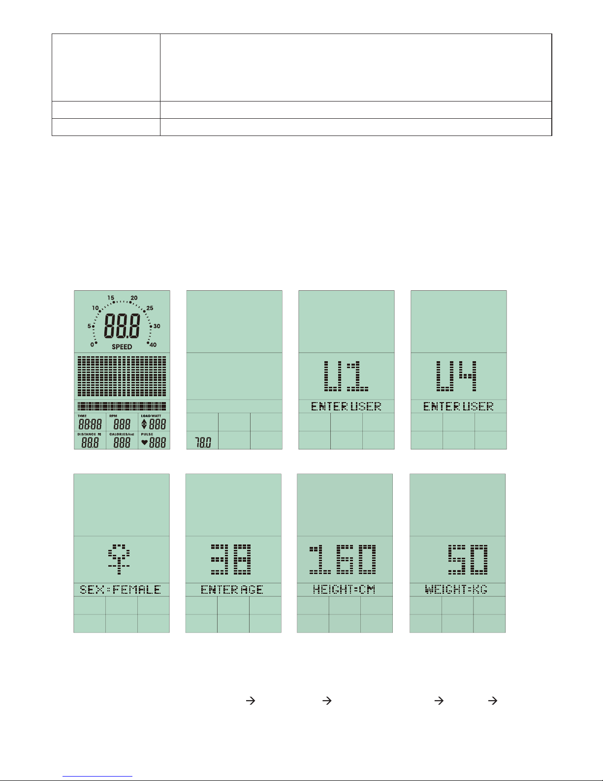
POWER ON
1. Connect power supply to the monitor or press the RESET button for 2 seconds, the LCD
will display all segment with a long- beep sound for 2 seconds and display 78.0 in below
(FIGURE 1 & 2).
2. User may turn the UP/DOWN joggle wheel to select User 1~4 and press ENTER for
confirmation (FIGURE 3~4).
And then preset user information for SEX, AGE, HEIGHT and WEIGHT. (FIGURE 4~7)
FIGURE 1 FIGURE 2 FIGURE 3 FIGURE 4
FIGURE 5 FIGURE 6 FIGURE 7 FIGURE 7
PROGRAMMING MODE
1. Program selections are MANUAL PROGRAM USER PROGRAM H.R.C. WATT
(FIGURE 8~12)

2. Use UP/DOWN joggle wheel to select the program you want and press ENTER to confirm.
Or press START/STOP button to start MANUAL mode immediately.
FIGURE 8 FIGURE 9 FIGURE 10 FIGURE 11
FIGURE 12
QUICK START IN MANUAL
1. Press ENTER to enter MANUAL program, and the screen is blinking (FIGURE 13).
2. Press START/STOP to start exercising. The resist level is adjustable during exercising
(FIGURE 14).
3. User can press START/ STOP to stop exercising
FIGURE 13 FIGURE 14

MANUAL MODE
1. After selecting MANUAL mode (FIGURE 13), user can use UP/DOWN joggle wheel to
increase or decrease level (from 1 to 16) and press ENTER to confirm.
2. User may preset exercise data (TIME, DISTANCE, CALORIES, PULSE), and press
START/STOP to start exercise.
User can press RESET to return to the MANUAL setting
3. Level is adjustable during training.
FIGURE 13 FIGURE 14 FIGURE 15 FIGURE 16
FIGURE 17 FIGURE 18 FIGURE 19 FIGURE 20
USER SELECT U1-U4
PRESS
RESET 3 SEC
TO RESET
CLOCKWISE OR
ANTI-CLOCKWISE
MANUAL mode
PRESS
ENTER
CLOCKWISE OR
ANTI-CLOCKWISE
CLOCKWISE OR
ANTI-CLOCKWISE
PRESS
ENTER
PRESS
ENTER
CLOCKWISE OR
ANTI-CLOCKWISE
CLOCKWISE OR
ANTI-CLOCKWISE
PRESS
ENTER CLOCKWISE OR
ANTI-CLOCKWISE
CLOCKWISE OR
ANTI-CLOCKWISE
PRESS
ENTER
PRESS
ENTER
FUNCTION SELECT
T
I
M
E
P
U
L
S
C
A
L
O
R
I
E
S
D
I
S
T
A
N
C
E
E
CLOCKWISE OR
ANTI-CLOCKWISE
PRESS
ENTER
START/
STOP
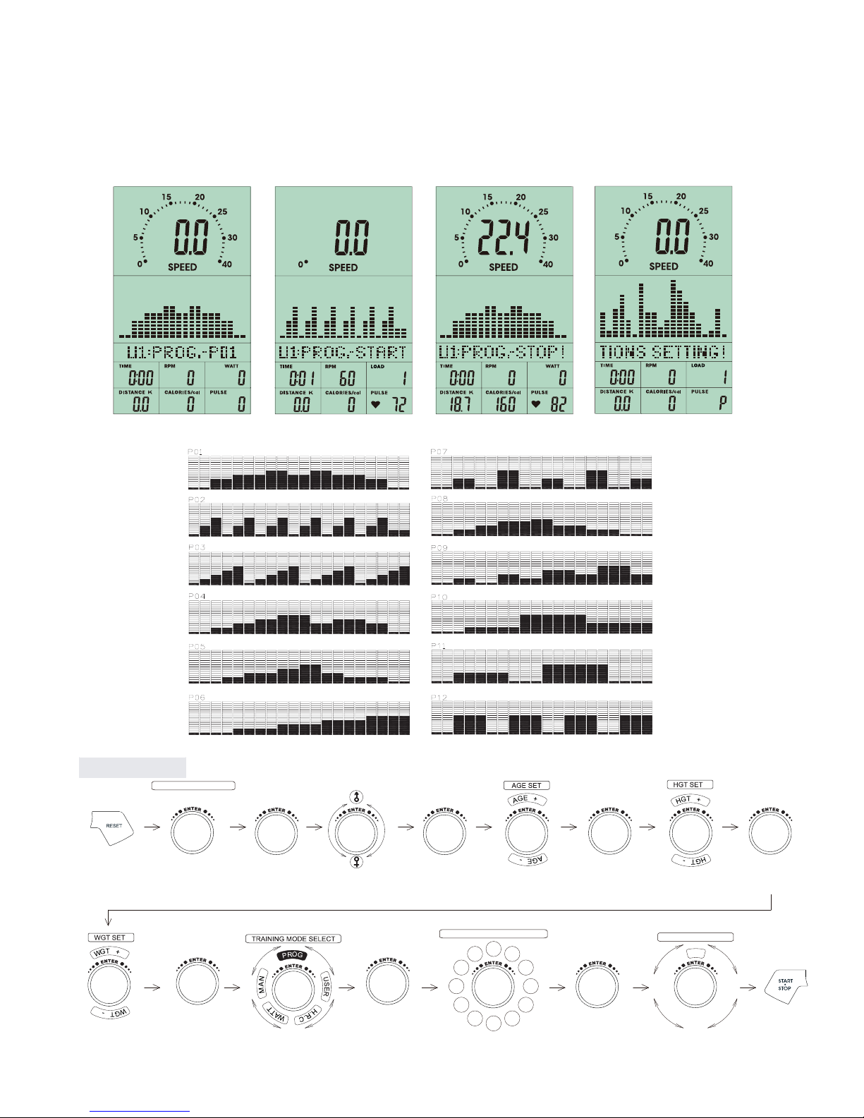
FIGURE 21 FIGURE 22 FIGURE 23 FIGURE 24
PROGRAM MODE
1. After enter PROGRAM mode, user and turn the UP/DOWN joggle wheel to select program
profile from P1 to P12, then press ENTER to confirm.
2. User can preset the TIME data then press START/STOP to start exercise.
3. After start training, TIME will be counted down. When the TIME is counted to 0, the
screen is flashing and the alarm is ringing. User can press any button to stop the alarm.
USER SELECT U1-U4
PRESS
RESET 3 SEC
TO RESET
CLOCKWISE OR
ANTI-CLOCKWISE
PROGRAM mode
PRESS
ENTER
CLOCKWISE OR
ANTI-CLOCKWISE
CLOCKWISE OR
ANTI-CLOCKWISE
PRESS
ENTER
PRESS
ENTER
CLOCKWISE OR
ANTI-CLOCKWISE
CLOCKWISE OR
ANTI-CLOCKWISE
PRESS
ENTER CLOCKWISE OR
ANTI-CLOCKWISE
PRESS
ENTER
PRESS
ENTER
FUNCTION SELECT
T
I
M
E
CLOCKWISE OR
ANTI-CLOCKWISE
PRESS
ENTER
PROGRAM SELECT P1 to P12
P1 P2
P3
P4
P5
P7 P6
P8
P9
P10
P11
P12
CLOCKWISE OR
ANTI-CLOCKWISE

to 0, the screen is flashing and the alarm is ringing. User can press any button to stop the
alarm.
FIGURE 25 FIGURE 26 FIGURE 27 FIGURE 28
FIGURE 29
USER PROGRAM
1. After enter USER PROGRAM mode, the first column of the profile is blinking (FIGURE 25).
User may turn the joggle wheel to adjust the resistance level (FIGURE 26) to create his /
her own profile.
2. After setting (from column 1 to column 20), user may hold on pressing MODE button for 2
seconds to quit profile setting and enter TIME setting.
3. While making the profile setting, user can press RESET and return to the menu.
4. After start training (FIGURE 27~29), TIME will be counted down. When TIME is counted
USER SELECT U1-U4
PRESS
RESET 3 SEC
TO RESET
CLOCKWISE OR
ANTI-CLOCKWISE
USER mode
PRESS
ENTER
CLOCKWISE OR
ANTI-CLOCKWISE
CLOCKWISE OR
ANTI-CLOCKWISE
PRESS
ENTER
PRESS
ENTER
CLOCKWISE OR
ANTI-CLOCKWISE
CLOCKWISE OR
ANTI-CLOCKWISE
PRESS
ENTER CLOCKWISE OR
ANTI-CLOCKWISE
PRESS
ENTER
PRESS
ENTER
FUNCTION SELECT
T
I
M
E
CLOCKWISE OR
ANTI-CLOCKWISE
PRESS
ENTER
Repeating these opeartion till completing the setting of 20 ranges
CLOCKWISE OR
ANTI-CLOCKWISE
Hold on pressing for 2 seconds

FIGURE 29 FIGURE 30 FIGURE 31 FIGURE 32
FIGURE 33 FIGURE 34 FIGURE 35 FIGURE 36
USER SELECT U1-U4
PRESS
RESET 3 SEC
TO RESET
CLOCKWISE OR
ANTI-CLOCKWISE
H.R.C. mode
PRESS
ENTER
CLOCKWISE OR
ANTI-CLOCKWISE
CLOCKWISE OR
ANTI-CLOCKWISE
PRESS
ENTER
PRESS
ENTER
CLOCKWISE OR
ANTI-CLOCKWISE
CLOCKWISE OR
ANTI-CLOCKWISE
PRESS
ENTER CLOCKWISE OR
ANTI-CLOCKWISE
PRESS
ENTER
PRESS
ENTER
FUNCTION SELECT
T
I
M
E
CLOCKWISE OR
ANTI-CLOCKWISE
PRESS
ENTER
TRAINING MODE SELECT
.R
C
GAT
%05
%
57
%09
CLOCKWISE OR
ANTI-CLOCKWISE
HEART RATE CONTROL
1. After enter HEART RATE CONTROL mode, the screen will show heart rate percentage 55%,
75%, 90% and TARGET. User may select heart rate percentage by turning UP/ DOWN
joggle wheel for training.
2. User can preset the TIME data then press START/ STOP to start exercise.
3. After start training, TIME will be counted down. When the TIME is counted to 0, the
screen is flashing and the alarm is ringing. User can press any button to stop the alarm.
If there is no HR input for 5 seconds, LCD will display until HR signal input.
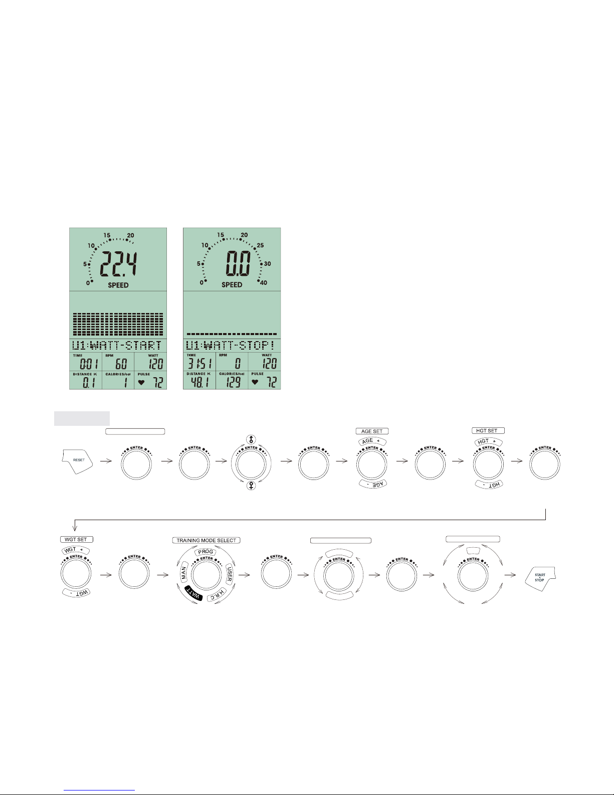
FIGURE 37 FIGURE 38
RECOVERY
After exercising for a period of time, keep holding on handgrips and press “RECOVERY”
button. All function display will stop except “TIME” starts counting down from 00:60 to 00:00.
Screen will display your heart rate recovery status with the F1, F2….to F6. F1 is the best, F6
is the worst. User may keep exercising to improve the heart rate recovery status. (Press the
RECOVERY button again to return the main display.)
WATT CONSTANT
1. In standby mode, select WATT and press ENTER to enter.
2. The preset watt value 120 is flashing on screen, use UP/ DOWN joggle wheel to set target
value from 10 to 350. Pressing START button to start training.
3. User can preset the TIME data then press START/STOP to start exercise.
4. After start training, TIME will be counted down. When the TIME is counted to 0, the
screen is flashing and the alarm is ringing. User can press any button to stop the alarm.
5. Watt value is adjustable during training. User can turn the joggle wheel to adjust the Watt
according to the instruction:
ɇʳ: Watt value > Setting value 25% --- User should show down
● : Watt value in the Setting value 25% ---User should keep the same speed
ϰʳ : Watt value < Setting value 25% --- User should ride faster
USER SELECT U1-U4
PRESS
RESET 3 SEC
TO RESET
CLOCKWISE OR
ANTI-CLOCKWISE
WATT mode
PRESS
ENTER
CLOCKWISE OR
ANTI-CLOCKWISE
CLOCKWISE OR
ANTI-CLOCKWISE
PRESS
ENTER
PRESS
ENTER
CLOCKWISE OR
ANTI-CLOCKWISE
CLOCKWISE OR
ANTI-CLOCKWISE
PRESS
ENTER CLOCKWISE OR
ANTI-CLOCKWISE
PRESS
ENTER PRESS
ENTER
FUNCTION SELECT
T
I
M
E
CLOCKWISE OR
ANTI-CLOCKWISE
PRESS
ENTER
WATT INSTALLED 120
3
5
0
+
1
0
-
CLOCKWISE OR
ANTI-CLOCKWISE

FIGURE 39 FIGURE 40
NOTE:
1. When user stop pedaling for 4 minutes, computer will enter into power save mode, all
setting and exercise data will stored until user start exercise again.
2. This computer requires 9V, 1A adaptor.
3. When computer act abnormal, please plug out the adaptor and plug in again.
Table of contents
Other Sportop Elliptical Trainer manuals

Sportop
Sportop VST60 Operation manual

Sportop
Sportop E7000P PLUS Operation manual

Sportop
Sportop E80 Operation manual

Sportop
Sportop E450 Operation manual

Sportop
Sportop E7000P PLUS Operation manual

Sportop
Sportop E-860P Operation manual

Sportop
Sportop E160 Operation manual

Sportop
Sportop E 8000P Operation manual

Sportop
Sportop E 7000P Operation manual

Sportop
Sportop RO 700 User manual


