Sportsman Aviation PITTS M12 User manual

SPORTSMAN AVIATION
PITTS M12
Thank you for choosing the Pitts M12. This quality BiPlane Aircraft ARF is a
lightweight, 40 size engine or electric offering that puts you behind the sticks of
the famous scale aircraft. This is one ARF that will stand out at the flight line, and
just wait til you see it fly! This beautifully built, high-quality M12 BiPe presented by
tates performance hobbies is ideal for intermediate and advanced flyers, to
perform breath-taking aerobatics.

PAGE 2 OF 22
CONTENTS
PLEASE READ CAREFULLY BEFORE COMMENCING...........................................................................................2
INTENDED USE...........................................................................................................................................................2
WARRANTY.................................................................................................................................................................3
WARNINGS..................................................................................................................................................................3
CAUTIONS...................................................................................................................................................................3
COVERING...................................................................................................................................................................4
GOING OVER THE COVERING..................................................................................................................................4
TIPS..............................................................................................................................................................................4
KIT CONTENTS:..........................................................................................................................................................5
ITEMS NEEDED TO COMPLETE MODEL..................................................................................................................6
HINGING AILERONS...................................................................................................................................................7
WING SERVO...............................................................................................................................................................7
BOTTOM WING ASSEMBLY ......................................................................................................................................8
TAIL ASSEMBLY.........................................................................................................................................................9
UNDERCARRIAGE....................................................................................................................................................12
WINGS........................................................................................................................................................................13
PUSH RODS...............................................................................................................................................................14
AILERON JOINING WIRE .........................................................................................................................................15
SEALING HINGE JOINS............................................................................................................................................16
MOTOR ASSEMBLY .................................................................................................................................................16
MOTOR ASSEMBLY .................................................................................................................................................17
MOUNTING THE COWL............................................................................................................................................19
FITTING PROP ADAPTOR AND SPINNER..............................................................................................................20
RADIO GEAR LOCATION.........................................................................................................................................20
PREFLIGHT PREPARATION....................................................................................................................................21
CONTROL THROWS.................................................................................................................................................21
PREFLIGHT CHECKS...............................................................................................................................................22
FLIGHT TESTING ......................................................................................................................................................22
WARNING!!
An R/C aircraft is not a toy! If misused, it can cause serious bodily harm and property damage. Fly only in open areas, and MAAA approved
flying sites. Follow all instructions included with your plane, radio, and engine.
PLEASE READ CAREFULLY BEFORE COMMENCING
This model is not a toy. It is a highly detailed functional scale model. We hope that this product will bring you hours of enjoyment and
entertainment. Due to the sophisticated technical nature of this product, it is important that you carefully review all of the following warnings,
cautions, and warranty terms. Likewise you should review and follow the following instructions for usage.
Due to the fact that Tates Performance Hobbies is constantly improving the quality and functional characteristics of its products some details,
colours, and functions may differ slightly from the images presented on the box and in the instructions.
IMPORTANT!
Before starting the assembly of your new ARF please inventory and inspect all parts and hardware for imperfections or damage.
Notify your local hobby shop or Tates Performance Hobbies immediately if there are missing or damaged parts.
Please read through the assembly manual carefully and follow the order of assembly before you start building the aircraft. This will help save
time and reduce the chance of building errors.
INTENDED USE
This plane should not be regarded as a toy. This is a mild aerobatic plane and is recommended for pilots who are looking to learn or move in to
more aerobatic type flying. Ideal for use at the park or flying field.
It is important to notify the place of purchase of any damage or problems with the model immediately. If you wish to return this aircraft for any
reason a fee may be charged.In addition the customer is responsible for all return shipping cost and all prior shipping cost will not be refunded.
Parts will be exchanged or replaced once the original item is returned at the owner’s expense. If you have any problems, please contact your
place of purchase or Tates Performance Hobbies.
We cannot insure the skill of the modeler and can not influence the builder during the construction or use of this aircraft, therefore, we will not be
accountable for any property damage, bodily injury or death caused by this aircraft.

PAGE 3 OF 22
WARRANTY
Tates Performance Hobbies guarantees that this model is free from defects both in material and craftsmanship on the date of purchase. This
guarantee does not cover any component parts damaged by use or modification. Tates Performance Hobbies liability will under no
circumstances exceed the original cost of the purchased model. Moreover, Tates Performance Hobbies reserves the right to change or modify
this warranty without notice.
If upon purchasing this product the buyer finds defects to the product as a result of the manufacturing process we recommend that you return
this product to the place of purchase to exchange or refund the product.
Given that Tates Performance Hobbies has no control over the final assembly or use of this product, Tates Performance Hobbies shall assume
no liability for damage caused resulting from the use by the user of the final user-assembled product. By using this product the user accepts all
resulting liability.
If the purchaser of this product is not prepared to accept the liability associated with the use of this product, they are advised to return this model
within 14 days to the place of purchase. The product must be in complete and unused condition along with receipt of purchase at the moment of
return.
WARNINGS
•Never leave the model in direct sunlight for prolonged periods of time.
•Never fly this model near an AIRPORT, check with your local airport authorities for minimum distance to available sites.
•Never use this model near power lines, radio towers, or other locations where there is known high radio wave or electromagnetic activity.
•Do not allow water or liquid to touch the model or any of the components.
•Store the model in a cool dry location as high humidity can damage the model and its components.
•Protect the model from bumps, jolts, and concussions from other hard objects as this could damage the model.
•Keep the model clean of dust, mud and dirt.
•Never place foreign objects on top of the model.
•Use the model ONLY in wide open spaces that are free of people, or at your local RC flight club.
•NEVER use the model near populated pedestrian areas. This could lead to damage of property or injury to bystanders.
•Prior to take off, always check that transmitter and receiver batteries are fully charged and are fresh. As battery power decreases the
quality of the radio signal diminishes and control over the model could fail.
•Please dispose of used batteries and electronic components in accordance with your municipal and federal Regulations relating to these
types of products.
•Keep in mind that those in your vicinity may also use radio control models. Please check prior to take off that you are using a unique
frequency to all those around you. Not doing so may cause you and others to lose control of the model.
•If the model does not properly respond to control inputs, land immediately and do not attempt to use the model until the cause has been
determined and fixed.
•After flying, switch off the power on the model and then the transmitter.
CAUTIONS
•This product is not suitable for children under 14 years of age, adult supervision of children is highly recommended.
•This kit contains a number of small parts which are fragile and may act as choking hazards.
•Please store and assemble this model well out of the reach of small children.
•Only use batteries of the same or equivalent type.
•The power supply terminals are not to be short-circuited.
•Do not use new and old batteries together. Do not mix different brands or kinds of batteries.
•Make sure to insert batteries with correct (+) and (-) polarity.
•If the aircraft gets wet, dry it, and stop operating to avoid short-circuiting that may cause hazards.
•Do not put fingers, hair, or clothes into the shafts or rotating parts of the model.
•NEVER LEAVE CHARGING BATTERIES UNATTENTED!!!!!!
PRODUCT CONTAINS SMALL PARTS - KEEP AWAY FROM YOUNG CHILDREN
NOT SUITABLE FOR CHILDREN UNDER 14 YEARS OF AGE UNLESS SUPERVISED BY AN ADULT
COLORS, SPECIFICATONS AND CHARACTERISTICS MAY BE DIFFERENT FROM PICTURE AND DESCRIPTON ON THE BOX AND
MANUAL.
The purchaser/operator accepts all responsibility of any and all structural or mechanical failures.
Before beginning the assembly of your Pitts Special, remove each part from its bag for inspection.
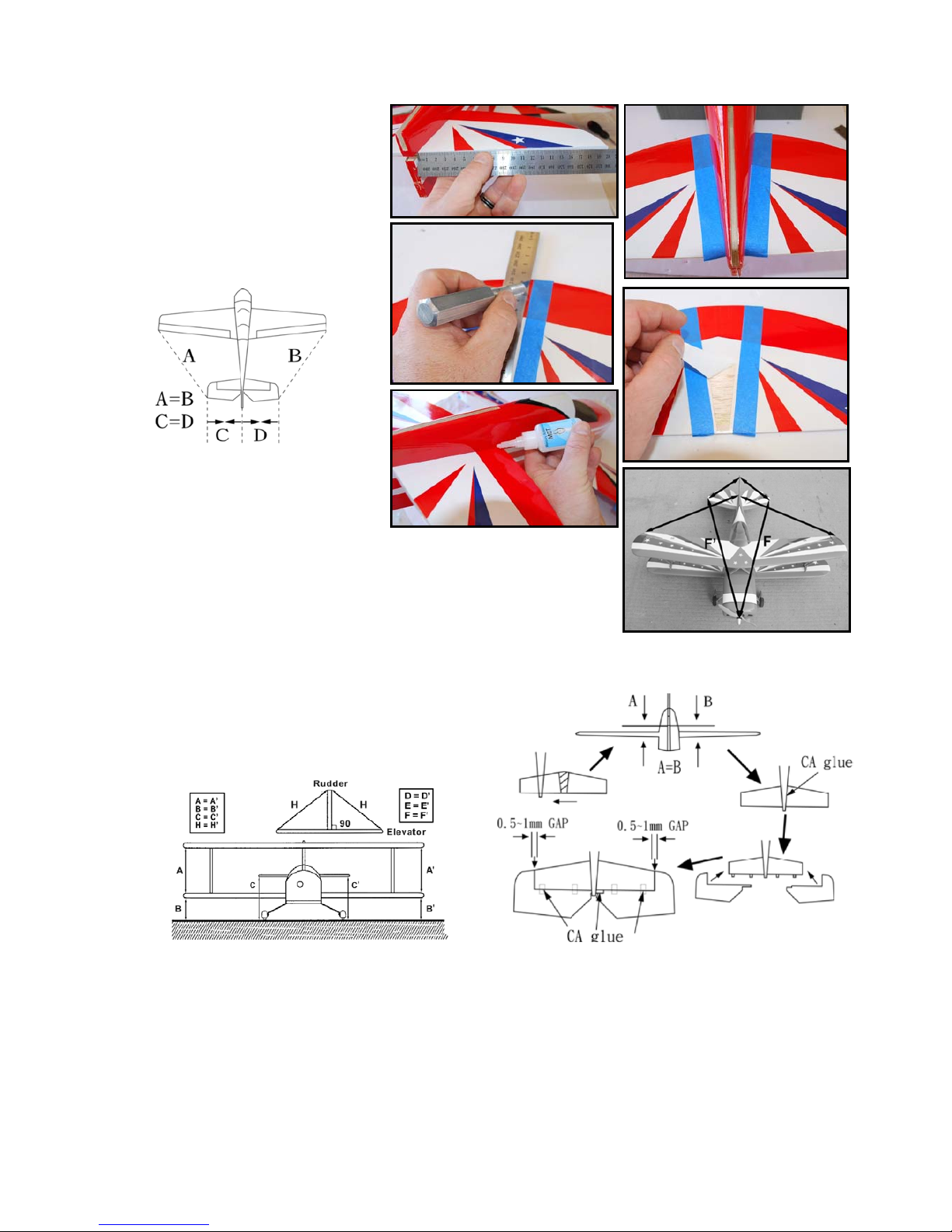
IMPORTANT INFORMATION ABOUT THE C/A-STYLE HINGES INCLUDED WITH YOUR AIRPLANE
The airplane uses C/A-style hinges to hinge the control surfaces. These hinges are designed to be glued into place using thin
C/A. Do not glue the hinges into place using any other type of glue, such as thick C/A or epoxy. Use of any adhesive other than
thin C/A could result in failure of the hinges during flight.
For flutter-free control surfaces and crisp control response, it is imperative that the hinges be glued in properly. This is
achieved by having a tight hinge gap (no more than 1/32" (.7mm) wide) and using plenty of thin C/A glue. Poor hinge installation
can lead to control surface flutter, which can result in a catastrophic failure of the airframe.
If the hinge(s) can't be pushed in far enough to achieve the proper hinge gap, you'll need to use a modeling knife to cut the
hinge slot(s) deeper.
Make sure to check the integrity of the hinges after the C/A fully cures.
IMPORTANT It is imperative that the aileron and elevator hinge gaps be sealed. Failure to do this can lead to control surface flutter,
which can cause your airplane to crash. Sealing the hinge gaps will also provide crisper control response and allow the
airplane to track straighter and fly truer, making trimming much easier. Its not as necessary to seal the rudder hinge gap.

PAGE 4 OF 22
COVERING
The covering material used on your airplane is real iron-on, heat-shrink covering material. It is possible with heat
and humidity changes that the covering material on your airplane may wrinkle or sag. This trait is inherent in all
types of heat-shrink material. To remove any wrinkles that might be visible you will need to use a heat-sealing
covering iron.
Follow this simple procedure to remove the wrinkles
Plug in and turn on the sealing iron to the medium-high temperature setting. Allow the sealing iron to heat up for
approximately 5 - 7 minutes.
After the sealing iron has reached temperature, lightly apply the sealing iron to the wrinkled section of the covering
material. Move the sealing iron slowly over the wrinkled section until the covering material tightens and the wrinkles
disappear.
IMPORTANT You will notice that the colour of the covering material will darken when it is heated. When the
covering material cools back down, it will return to its normal colour. If the colour layer smears from any of the
seams the temperature of the sealing iron is too hot. Turn the temperature dial down and wait about 5 minutes
for the sealing iron to adjust to the lower temperature. You can remove any excess colour streaks using a paper
towel soaked with a small quantity of Acetone.
During the covering process, sometimes colour may smear slightly from the seams. If you see any smeared
colours on the covering material, they can be quickly removed by simply wiping them off with a paper towel and a
small amount of Acetone.
GOING OVER THE COVERING
Before beginning the assembly of your M12, remove each part from its bag for
Inspection. The covering material is a standard china cover but is then painted. This is why it has a very nice finish
and if you like you and paint over it for scale detailing or touch ups.
TIPS
Make sure to test-fit the parts together before applying glue. This will ensure that the parts fit properly before gluing
them together.
When gluing anything that has a smooth surface, its important to lightly roughen the gluing surfaces with 220 grit
sandpaper. This will allow the glue to stick better. Also, never glue directly to the covering material. Always
remove the covering material from the
gluing surfaces prior to gluing the parts together.
When cutting away the covering material from the gluing surfaces, be careful to cut only through the covering
material. Try not to cut down into the balsa structure because that can compromise the integrity of the airframe.
We do not suggest storing your airplane in an extremely hot environment (like the back of your car in direct
sunlight) for any length of time. The extreme heat could cause the covering material to wrinkle or sag and possibly
damage the fragile components of the
radio control system.
Epoxy can be cleaned up before it dries using rubbing alcohol,(Metho) and C/A can be cleaned up before it dries
using C/A Debonder.

PAGE 5 OF 22
KIT CONTENTS:
Features
•Laser-cut balsa and ply construction
•Built-up fuselage
•One piece built-up bolt-on wings
•Fibre glass cowl and wheel pants
•Landing gear
•Pre-slotted C/A hinges.
•Hardware pack—bolts, nuts, lock nuts, C/A hinges
•Durable, lightweight landing wheels
•Linkages and control horns.
Plane Specs
Wing span: 49 in / 1245 mm
Wing area: 46.8 sq dm
Flying weight: 2500 g
Fuselage length: 43.5 in / 1105 mm

PAGE 6 OF 22
ITEMS NEEDED TO COMPLETE MODEL
Motor
Magnum 46 or 52 four stroke. Recommended
Propeller
(XOAR 12x4) Recommended
TY 63mm white spinner
Radio System
2 x aileron servos
1 x rudder servo
1 x elevator servo
Receiver
4-7 channel Recommended
OPTIONAL
TY Hinge Tape
Tools:
•Modeling knife.
•Electric drill and selection of bits.
•Phillips screwdriver.
•Needle nose pliers.
•Wire Cutters.
•Pins.
•Ruler and tape measure.
•Pen, pencil or felt tipped marker.
•Flat building board.
•Building squares and blocks.
•Masking tape.
•Clear tape (optional).
•TY Allen keys.
•TY Z bender.
Mercury Adhesives:
•Thin CA (M5T)
•High Performance CA (M100XF)
•CA kicker (optional)
•Mercury Teflon tips.

PAGE 7 OF 22
HINGING AILERONS
Place a pin though the centre of all the
hinges.
Slide the hinges into the ailerons up to
the pin half way.
If the hinges are too tight, slightly widen
the slot with a hobby knife.
Slide the aileron on to the wing.
Remove the pin and butt the aileron up
tight.
Check to see if you can get full
deflection of aileron with a minimum
hinge gap.
Centre the aileron.
Glue the hinges in place with thin C/A.
Repeat for other wing.
WING SERVO
Locate the aileron servo opening that is
covered by film and cut an opening for the
aileron servo in the bottom of the wing.
Remove covering with a hot wire or hobby
knife.
Use a hot wire to cut the covering away
from the slot in the servo cover.
Set the servo arm 90 degrees to the servo.
Lay the servo with the output arm through
the servo plate cut out.
Align the servo mounting on to the servo
cover.
Glue the blocks in position with C/A.
Connect a TY 100mm servo extension to
the servo lead.
Place TY safety lock in place.
Use pointy nose plies to pull the string out of
the servo hole and tape to the servo
extension.

PAGE 8 OF 22
Now pull the extension through the wing
until servo sits in place.
(A pin vice is a good tool to use with the
small drill bit for drilling a pilot hole for the
servo plate screws).
Insert the servo in place so the output arm
is closes to the front of the wing.
Secure servo plate with self tappers supplied.
Aileron push rods
Fit control horn in line with servo arm.
Fit push rod Z bend end to the servo arm.
Thread the clevis on to the other end.
Repeat process for other side.
BOTTOM WING ASSEMBLY
Fit bottom wing on to fuselage.
Now locate the two bolt holes through
the covering.
Use the two bolts and titan in to the
fuselage.
Measure from the wing tip to the tail (E). Make sure the wing is
centered on the fuselage.
Test fit belly cover on to the bottom of the wing.
Apply a canopy glue to the belly pan then tap in place till dry.
E

PAGE 9 OF 22
TAIL ASSEMBLY
Stablizer assembly
Slide stabilizer into the fuselage.
Measure from side of fuselage to tip of
stabilizer on both sides and adjust the
stabilizer until measurements are equal.
Measure from wing tip to stabilizer on
both sides and adjust till equal.
Place tape on each side of the stabilizer.
Top and bottom. Were the fuselage joins
the stabilizer.
Remove stabilizer from plane.
Use a hobby knife and a ruler to remove
the covering in-between the tape.
Slide stabilizer back into fuselage.
Remeasure from wing tip to stabilizer and stabilizer to fuselage.
Align equally.
Now align the stabilizer to the wing until it is parallel.
You may have to pack with balsa or mach sticks until it
aligns. Refer to picture.
When satisfied with all the measurements, glue stabilizer in place with thin mercury CA.

PAGE 10 OF 22
Elevator assembly
Locate the hinges for the elevator. Place a T pin through the centre of them.
Roughen the ends of the elevator joining wire with a file to aid in the glue
sticking.
Slide the hinges in to the elevator halves. If they are tight to get into the slots
slide a hobby knife in to slightly enlarge the hole.
Apply high performance C/A to the
elevator joining wire and insert into the
elevators.
Lay the elevators on a flat surface while
glue dries.
Now insert the elevator into the
stabilizer and glue hinges in place with
thin C/A.
Ensure the fuselage is level so the C/A
runs into the hinge attachment area.
You should leave enough of a hinge
gap to allow for full deflection but no
more than is necessary for full
deflection.
It should be a little less than a credit
card thickness.
Now move the elevator up and down to
make sure there is fluid movement and
not binding.
Fin assembly
Slot fin all the way down in to the
fuselage slot.
Now place tape on the fin where it joins
to the fuselage.
Remove fin from fuselage and cut
covering along the tape with hobby knife
and ruler.
Remove covering.
Replace fin back into the fuselage.
Measure from top of fin to the end of the
stabilizer to make sure it is 90 degrees
to the stabilizer.

PAGE 11 OF 22
Also looking at the tail from the front of
the plane.
You can check that the fin and
stabilizer is square to each other.
The wings should be parallel to the stabilizer
as well.
Rudder assembly
Locate the hinges for the rudder.
Place a T pin through them as you did
for the elevator.
Slide the hinges into the rudder then
slide the rudder into the fin.
Remove T pins from hinges.
Check to see if you have full rudder
deflection with a little as possible hinge
gap.
Place plane on its side and apply thin
C/A to the hinges on both sides.
Tail wheel assembly
Now install the tail wheel in to the rudder.
Mark were the tail wheel steering wire lines
up on the bottom of the rudder.
Make sure the vertical tail wheel wire or
hinging point of the tail wheel is in line with
the hinge line otherwise the rudder will jam
on full deflection.
Drill a hole the same size as the steering wire
in to the bottom of the rudder as deep as
needed to be.
Dry fit the steering wire in to the hole drilled.
Mark were the holes for the tail wheel plate
on the fuselage.
Drill a pilot hole for the self tappers to hold
the tail wheel plate on.
Dry fit the tail wheel assembly and secure
with self tappers.
Make sure you can still get full rudder
deflection.
If not move the tail wheel assembly until you
can.
To secure apply medium C/A to steering wire
replace back on rudder and secure with self
tappers.

PAGE 12 OF 22
UNDERCARRIAGE
Installing the landing gear, axles,
wheels and wheel pants and then attach
to the bottom of the fuselage.
The axle, axle bolts, washers and nuts
are attached as shown.
Slide the bolt though the undercarriage
leg.
Now place 2 nuts on to the bolt and
tighten.
Now slide wheel on to bolt.
Followed by a lock nut.
Tighten the lock nut up to the wheel but
not too tight that the wheel can’t spin.
Cut off the left over bolt.
Now slide the wheel pants over the
double nuts.
When in position drill a pilot hole in to
wheel pant and hold in position with self
tapper.
Locate the undercarriage slots in the
side of the fuselage and open.
Slide undercarriage into the bottom of
the fuselage.
Locate the two bolt holes in the
fuselage.
Screw the two fine thread bolts supplied into the undercarriage to secure.

PAGE 13 OF 22
Tip
It is a good idea to go around
the entire glue joint in the
fuselage with the high
performance (M100XF) glue
for piece of mind.
WINGS
Locate top wing Cabane
pieces.
Bolt together as shown in
photo.
Open the slots in the side of
the fuselage for the cabanes.
Slide cabanes in and secure
with bolts.
Bolt the Cabane to the top
wing but do not tighten.
Wing struts
Locate the two Inter plane
struts.
Use a hot wire to remove the
covering from the top and
bottom wings for the strut
support lugs.
Glue the 8 lugs into position
on wings.
Open the holes in the struts
up for the bolts.
There are many ways the
struts can fit so be sure to get
the angle and radius sitting
right on the wings.
Push the fine thread bolts supplied in from the wing tips.
Secure with lock nuts.
When all the struts and bolts are fitted and nuts on finger tight go through and tighten all the strut bolts and cabane
bolts.

PAGE 14 OF 22
PUSH RODS
Set the servos at 90 degrees.
Use the supplied push rods.
There is a Z bend on one end
which goes through the
control horn.
The other end will go though
the rod stopper on the servo.
Locate the push rode tube in the side tail of the fuselage and open so the push rode can go through.
Fit push rod in to the fuselage.
Elevator and rudder servos
Trim the push rod tubes back to the
former this will allow for more servo travel.
Apply a small drop of thin C/A on the tube
to secure against slipping.
Cut servo arm in to a half arm.
Drill out servo arm and fit rod stopper.
Apply a small drop of C/A to the nut on
the rod stopper to lock from coming lose.
Be sure that the rod stopper can spin
freely around in the servo horn.
Fit servo in to the servo tray with the
output shaft to the back.
Drill a pilot hole for each servo screw.
Secure servo in to position.
Place servo arm with rod stoper onto
servo.
Repeat process for the other servo.

PAGE 15 OF 22
Elevator and Rudder horn attachment
Locate control horn.
Hold in position on
elevator in line with
the push rod and
on the edge of the
hinge line.
Drill two holes with a pin vice drill.
Place the bolts through and fit backing
plate and tighten.
Trim the excess bolt length off with side
cutters.
Apply a small amount of thin C/A on to
the backing plate bolts to lock in position.
Repeat process for Rudder.
AILERON JOINING WIRE
Sit the plane on its wheels.
Measure in from the fuselage side along
the aileron 100mm and mark the spot.
Mount a control horn in a reverse way to
the aileron horn.
(Pointing backwards with the holes
lining up over the trailing edge of the
aileron).
Measure the same on the bottom of the
top wing aileron.
Fit a control horn to the bottom of the
top aileron in the same fashion as you
did for the bottom aileron
Connect a clevis to both ends of the
push rod supplied.
Fit the push rod to the second hole in on the control surface.
Set the bottom aileron to a neutral position.
Adjust the clevises till you get the top ailerons in a neutral position.
When the aileron servo is powered up with the radio there will be more up then down aileron this is normal.

PAGE 16 OF 22
SEALING HINGE JOINS
It is recommended to use TY hinge tape to seal all the hinge joints, this will reduce the chance of flutter and will aid
in trimming the plane.
1. Cut tape to length of control surface.
2. Place 50% of the tape on the trailing edge
surface.
3. Hold the control surface as far open a
possible.
4. Push tape down in to the control surface
gap.
5. Now push the rest of the tape down on to
leading edge of the control surface.

PAGE 17 OF 22
MOTOR ASSEMBLY
Push the engine cowl on to the fuselage
into position.
Measure from the fire wall to the front of
the cowl.
Hold the engine mount up to the magnum
motor.
Measure from the back of the engine
mount to the prop driver on the motor.
Slide the motor back and forward until you
get the same measurement + 5mm
clearance that you did for the fire wall to
the cowl.
Mark the motor mount hole in the engine
mount.
Bolt motor onto engine mount.
Measure the engine mount mounting
holes.
Transfer the measurement on to the fire
wall.
Use the cross hair lines to measure from.
These have the off set to allow for the built in
right trust.
Drill the fire wall for the four bolts and blind
nuts.
Fit blind nuts to fire wall.
Bolt engine mount in to place.

PAGE 18 OF 22
Fuel Tank
Push the three aluminum tubes into the
rubber bung.
Push the backing plate on.
Push the front plate on followed by the
centre bolt.
Get the centre bolt started but do not
tighten.
Ben the top pipe up to the top of the
tank.
Bend the bottom pipe to the bottom of
the tank.
Use fuel tube to extend the pipes so
they will reach.
Cut a piece of silicon tube for the pick
up line.
Fit the clunk to the end.
Test fit the bung in to the tank to see if
the lengths are all ok.
The clunk should not hit the end of the
tank.
Replace the bung into the tank and
tighten the centre bolt.
Fit the external fuel lines and mark them
for easy fitting reference for later.
Mark the top of the fuel tank witch will
be the exhaust line.
Slide fuel tank in to the fuselage.
Hold the fuel tank into position with
cable ties.
Now connect the fuel lines to the motor.
Top of the tank is exhaust line.
The clunk line goes to the carburetor.
The bottom of the tank goes to a TY fuel
dot for easy refueling.

PAGE 19 OF 22
Throttle servo
Fit throttle servo.
Fit throttle tube bracket in line
with servo output arm.
Drill a hole in the firewall in line
with the throttle arm on the
carburetor.
Push tube through hole cut to
length and glue.
Push the throttle wire through the
tube.
Fit wire on to the rode stopper on
the servo and secure.
Fit the Z bend end on to the
throttle arm.
You may have to bend the wire
around the motor to allow for easy
movement from idle to full throttle.
Power the throttle servo up and set transmitter on half throttle.
Set the servo out put arm at 90 degrees.
Set the carburetor on half throttle.
Tighten up the rod stopper the servo.
Check the operation of the throttle to see if you have a free movement from idle to full throttle.
MOUNTING THE COWL
Slide cowl on to the front of the
fuselage.
Tape into position.
Fit prop adaptor and spinner
backing plate.
Use the spinner backing plate as a
reference to align the cowl properly.
There are 4 small ply plates inside
the fuselage.
Line these up and drill a pilot hole
with your pin vice and drill.
Secure in place with the supplied
self tapers.
You will need to use a dremal to cut
the cowl out to allow for exhaust
ect.

PAGE 20 OF 22
FITTING PROP ADAPTOR AND SPINNER
Fit the prop and spinner.
1. Spinner back plate.
2. Xoar prop.
3. Washer.
4. Nut or weighted spinner nut if nose weight needed.
5. Spinner cone.
Tighten the prop nut tight before putting the spinner cone on.
If using a wood prop check and retighten after the first flight.
Note before tightening the prop up too tight check to see if the spinner
cone bolt holes to the backing plate line up.
Fit the spinner cone with the 2 bolts supplied.
RADIO GEAR LOCATION
Glue a small piece of ply in the gap to
create a place for the TY switch harness.
Fit switch harness in to position as per
photo.
Mount battery up the front of the fuselage
with cable ties for nose weight.
Mount your receiver in place with Velcro.
Refer to photo as a guide for placement
Table of contents
Other Sportsman Aviation Toy manuals

Sportsman Aviation
Sportsman Aviation Paramount 61 3D User manual

Sportsman Aviation
Sportsman Aviation POLECAT RACER .40 Instruction Manual

Sportsman Aviation
Sportsman Aviation Waco 60 ARF User manual

Sportsman Aviation
Sportsman Aviation Excelleron 90 User manual

Sportsman Aviation
Sportsman Aviation Giant Scale Corby Starlet User manual

Sportsman Aviation
Sportsman Aviation F4U Corsair ARF User manual