Spotnails DSP779 User manual

DSP779
AIR DRIVE PLIER
OPERATION and MAINTENANCE MANUAL
WARNING
BEFORE OPERATING THIS TOOL, ALL OPERATORS SHOULD STUDY THIS
MANUAL, TO UNDERSTAND AND FOLLOW THE SAFETY WARNINGS AND
INSTRUCTIONS. KEEP THESE INSTRUCTIONS WITH THE TOOL FOR FUTURE
REFERENCE. IF YOU HAVE ANY QUESTIONS, CONTACT YOUR DISTRIBUTOR.

2
INTRODUCTION
The SP50 is a precision-built tool; designed for high speed, high volume stapling. These tools
will deliver efficient, dependable service when used correctly and with care. As with any fine
power tool, for best performance the manufacturer’s instructions must be followed. Please
study this manual before operating the tool and understand the safety warnings and cautions.
The instructions on installation, operation and maintenance should be read carefully, and the
manual kept for reference. NOTE: Additional safety measures may be required because of your
particular application of the tool. Contact your distributor with any questions concerning the
tool and its use.
INDEX
Safety Instructions ..............................................................................................................2
Air Supply and Connections ..............................................................................................2
Loading Tool ........................................................................................................................3
Operation..............................................................................................................................3
Maintaining the Tool............................................................................................................3
Loading the SP50 Series Stapling Plier.............................................................................5
Replace Driver Piston or Driver .........................................................................................8
Replace Anvil .......................................................................................................................9
Replace Driver Guide ..........................................................................................................10
Replace Pusher or Spring...................................................................................................11
Parts List ..............................................................................................................................12
Exploded View of Tool.........................................................................................................13
SAFETY INSTRUCTIONS
WARNING EYE PROTETION which conforms to ANSI specifications and provides
protection against flying particles both from the FRONT and SIDE should
ALWAYS be worn by the operator and others in the work area when loading,
operating or servicing this tool. Eye protection is required to guard against
flying fasteners and debris, which could cause severe eye injury.
The employer and/or user must ensure that proper eye protection is worn. Eye
protection equipment must conform to the requirements of the American
National Standards Institute, ANSI Z87.1-1989 and provide both frontal and side
protection. NOTE: Non-side shielded spectacles and face shields alone do not
provide adequate protection.
WARNING CAUTION: ADDITIONAL SAFETY PROTECTION will be required in some
environments. For example, the working area may include exposure to noise
level which can lead to hearing damage. The employer and user must ensure
that any necessary hearing protection is provided and used by the operator and
others in the work area. Some environments will require the use of head
protection equipment. When required, the employer and user must ensure that
head protection conforming to ANSI Z89.1 1986 is used.
AIR SUPPLY AND CONNECTIONS
WARNING Do not used oxygen, combustible gases, or bottle gases as a power source for
this tool as tool may explode, possibly causing injury.
WARNING Do not use supply sources which can potentially exceed 200 P.S.I.G as tool may
burst possibly causing injury.
WARNING The connector on the tool must not hold pressure when air supply is
disconnected. If a wrong fitting is used, the tool can remain charge with air after
disconnecting and thus will be able to drive a fastener even after the air line is
disconnected possibly causing injury.

3
WARNING Do not pull trigger or depress contact arm while connected to the air supply as
the tool may cycle, possibly causing injury.
WARNING Always disconnect air supply:
1.) Before making adjustments;
2.) When servicing the tool;
3.) When Clearing a jam;
4.) When tool is not in use;
5.) When moving to a different work area, as accidental actuation may occur,
possibly causing injury.
LOADING TOOL
WARNING When loading tool; 1.) Never place a hand or any part of body in fastener
discharge area of tool; 2.) Never point tool at anyone; 3.) Do not pull the trigger
or depress the trip as accidental actuation may occur, possibly causing injury.
OPERATION
WARNING Always handle the tool with care; 1.) Never engage in horseplay; 2.) Never pull
the trigger unless nose is directed toward the work; 3.) Keep others a safe
distance from the tool while tool is in operation as accidental actuation may
occur, possibly causing injury.
WARNING The operator must not hold the trigger pulled on contact arm tools except during
fastening operation as serious injury could result if the trip accidentally
contacted someone or something, causing the tool to cycle.
WARNING Keep hands and body away from the discharge area of the tool. A contact arm
tool may bounce from the recoil of driving a fastener and an unwanted second
fastener may be driven possibly causing injury.
WARNING Check operation of the contact arm mechanism frequently. Do not use the tool if
the arm is not working correctly as accidental driving of a fastener may result.
Do not interfere with the proper operation of the contact arm mechanism.
WARNING Do not drive fasteners on top of other fasteners or with the tool at an overly
steep angle as this may cause deflection of fasteners which could cause injury.
MAINTAINING THE TOOL
WARNING When working on air tools note the warnings in this manual and use extra care
when evaluating problem tools.
OPERATING PRESSURE
WARNING
The operating pressure of the SP50 series plier is To prevent accidental
36 to 55 p.s.i (3.9kg/cm²). Tool wear will be greatly firing, disconnection air
increased if excessive pressure is used. supply:
炽before making
adjustments
炽when servicing the tool
炽when clearing jams
炽when tool is not in use
4
SETTING THE CORRECT PRESSURE
WARNING
The air equipments will vary, depending on the Do not use oxygen or
material to be stapled and the staple size. Do not combustible gases as a
use more air pressure than is required to drive the power sources which can
staple in the specific job. To determine best setting, potentially exceed 200
start at low pressure and increase pressure until drive P.S.I as tool may explode.
is satisfactory. Using excess pressure increases tool
wear on the plier and wastes compressed air.
WARNING
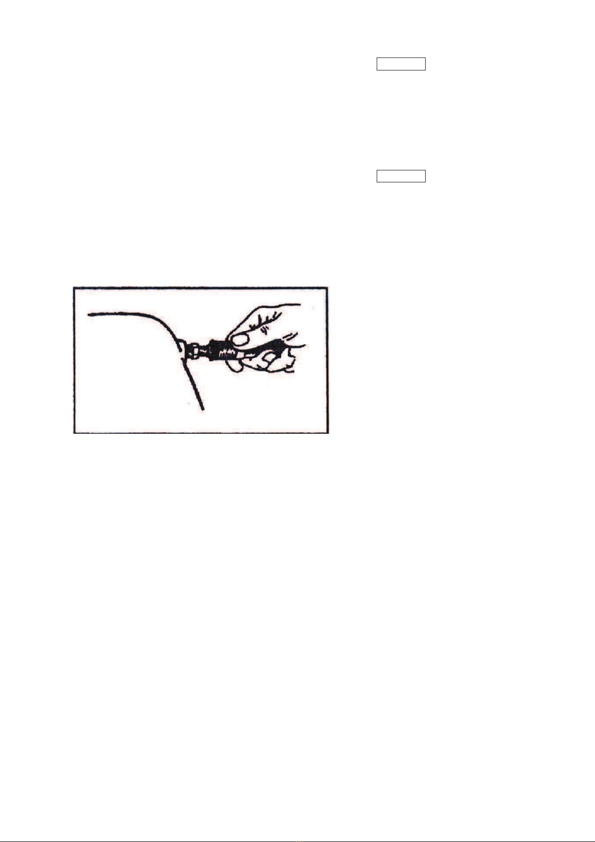
QUICK DISCONNECT FITTINGS
NOTE:The air supply
Install a free –flow connector plug on the nailer. system must be capable
Thread is 1/4” N.P.T. of maintaining the
Install a connector socket on the air hose. For required air pressure at
best performance, fitting should have minimum the tool when it is
inside dia. of .190”(4.8mm). operated at its highest
cycle speed. Inadequate
air supply will result in a
loss of power and
inconsistent driving after
the first cycle when the
tool is operated in high
speed bursts.
Always attach a
free-flow-connector plug to the
plier. If a wrong fitting is used,
the tool can remain charged
with air after disconnecting,
and thus will be able to cycle
even after the air line is
unplugged.
REGULATORS
Most air supply equipment will produce pressures NOTE: Air compressors used
that exceed the SP50’s maximum operating pressure, to supply compressed air to
55 p.s.i (3.9kg/cm²). A pressure regulator is required this plier should comply with
to control the operating pressure. The flow capacity the requirements of the
must be sufficient for the air usage at the installation. American National Standards
Institute Standard B19.3-1972,
Safety Standard for
HOSES
Compressors for Process
Air supply equipment should have a 85 p.s.i. Industries.
(6.0 kg/cm²) working pressure rating (or 150 percent
of the maximum pressure that could be produced in NOTE: Make sure air lines
the air system.) and fittings are clean before
connecting.
AIR CONSUMPTION
The SP50 requires 1.75 cubic feet per minute of free air to operate at the rate of 100 staples
per minute, at 55 p.s.i.
Take the actual rate at which the plier will be run to determine the amount of air required.
For instance, if your staple usage averages 50 staples per minute, you need 50% of the
7.75c.f.m. which is required for running at 100 staples per minute.
5
LOADING THE SP50 SERIES STAPLING PLIER
WARNING EYE PROTECTION which conforms to ANSI specifications and provides
protection against flying particles both from the FRONT and SIDE should
ALWAYS be worn by the operator and others in the work area when loading,
operating or servicing this tool. Eye protection is Required to guard against
flying fasteners and debris, which could cause severe eye injury.
The employer and/or user must ensure that proper eye protection is worn. Eye
protection equipment must conform to the requirements of the American
National Standards Institute, ANSI Z87.1-1989 and provide both frontal and side
protection.
NOTE: Non-side shielded spectacles and face shields alone do not provide
adequate protection.
WARNING TO PREVENT ACCIDENTAL INJURIES:
炽Never place a hand or any other part of the body in nail discharge area of tool
while the air supply is connected.
炽Never point the tool at anyone else.
炽Never engage in horseplay.
炽Never pull the trigger unless nose is directly towards the work.
炽Always handle the tool with care.
炽Do not pull the trigger or depress the trip mechanism while loading the tool.
MODEL SP-50 SERIES AIR DRIVE PLIERS
MODEL ANVIL STAPLES
SP-50-10B-A ANVIL A SB103020
3/8” (9.5mm)
1/2”(12.7mm)
5/8”(15.8mm)
SP-50-10B-B ANVIL B
SP-50-10B-CL ANVIL CL
SP-50-10B-CR ANVIL CR
SP-50-5B-A ANVIL A SB5019
1/4” (6.3mm)
3/8” (9.5mm)
1/2” (12.7mm)
5/8” (15.8mm)
SP-50-5B-B ANVIL B
SP-50-5B-CL ANVIL CL
SP-50-5B-CR ANVIL CR
1)Open the Magazine: WARNING
Pull cover back until locked by detent pin. Disconnect the air supply before
making adjustments.
2)Load Staples:
Insert a stick of staple and push forward in CAUTION: Do not attempt to operate
the channel. this plier without material between the
Insert a second stick of staples. shuttle and clincher to avoid damaging
the driver tip.
3)Close magazine:
Push the lock release tab(located at front of
magazine cover) down and push the cover
forward until its locked by the detent pin.
FILTERS
Dirt and water in the air supply is a major cause of wear in air tools. A filter will help to get
best performance from this plier. The filter must have adequate flow capacity for the specific
installation. The filter has to be kept clean to be effective in cleaning the air. Consult the
filter manufacturer’s instructions on proper maintenance. Clean and empty the filter as
needed. A dirty and clogged filter will also cause a pressure drop, which can reduce the
pliers performance.

6
Frequent but not excessive lubrication is required for best performance. Oil added
through the air line connection will lubricate the internal parts. Use Mobil Velocite
#10 oil or an equivalent. Do not use detergent oil or oil additives because the seals
and bumpers in the tool may be attacked by the oil.
If an air line lubricator is used, add oil during use by squirting oil into the air fitting
on the tool once or twice a day. Only a few drops at a time are required. Too much oil
will collect inside the tool and will be noticeable in the exhaust.
For cold weather operation, near and below freezing, the oil and water present in the
air line may freeze and prevent operation. We recommend the use of permanent
antifreeze (ethylene glycol) as a cold weather lubricant. Note that some commercial
air line drying liquids attack o-rings and seals – do not use these low temperature air
dryers without checking compatibility.
WARNING
When working on air tools, note the warnings in this manual, and use extra care when
evaluating problem tools.
REPLACEMENT PARTS
Replacement parts are commended. Do not WARNING
Eye protection
use modified parts or parts which will not
should be worn by the person
give equivalent performance to the original
operating or testing the plier, and
equipment. When ordering replacement parts
by others in the work area.
specify by part number.
ASSEMBLY PROCEDURES FOR SEALS
When repairing a plier make sure the internal WARNING
Disconnect the air
parts are clean and freshly lubricated.
supply supply before making
Use Parker O-lube or equivalent on all “O” rings
adjustments,servicing the tool,
Coat each “O” rings with O-lube before
clearing jams, or when tool is
assembling. Use a small amount of oil on all
not in use.
moving surfaces and pivots. After reassembly,
add a few drops of Velocite #10 oil or equivalent,
through the air line fitting before testing.
TROUBLE SHOOTING
Shuttle Punches Through Board:
Pressure too high; staple leg too short.
Staple Leg Buckles And Flattens Against Work Surface:
Staple Leg too long, shuttle not down against work due to worn shuttle piston o-ring.
Driver Punches Through Board:
Worn driver piston bumper.
Staple Ejects From Nose Before Shuttle Contacts Work Surface:
Worn upper driver piston o-ring; excessive air pressure.
Staple Ejects From Rear Opening In Shuttle:
Worn driver piston o-ring.
Air Leakage Through Exhaust Port:
Worn upper driver piston o-ring; worn upper shuttle piston o-ring; worn valve stem seat.
Air Leakage Through Nose Piece:
Worn lower driver piston o-ring; worn shuttle piston o-ring.

7
Staples Tumbling In Staple Channel:
Feed springs overstressed; feed springs broken; pusher binding on magazine core; dirt
inside magazine; excessive air pressure.
CLEANING JAMS:
Do not attempt to clear jammed staples by firing the tool to clear jam:
1. Disconnect Air supply.
2. Pull back top guide assembly and staples.
3. Pull down shuttle.
4. Remove jammed staple either from opening at the rear of shuttle or form drive
track behind the magazine assembly.
To clear jam caused by tumbled staple or if jam can not be cleared as outlined
above:
1. Be sure air supply is disconnected and top guide is pulled back.
2. Remove staples.
3. Snap magazine spring off magazine back.
4. Lift rear of magazine up and pull magazine back.
5. Remove jammed staple.
6. Slide magazine forward, aligning locating pins with holes in guide.
7. Push rear of magazine; do so with pin in magazine, block engages hole in
frame.
8. Wedge magazine spring back onto magazine block.
*Special maintenance instructions:
These are threaded parts that have been assembled with a plastic thread locking
compound. They should be replaced in a SPOTNAILS distributor. However, if they
must be replaced in the field, they may be separated by heating parts to
approximately 450°F when the compound become plastic. Clean parts thoroughly.
Degrease threads with Loctite solvent #75559, apply Locite grade 277, and
assemble. Allow 1/2 – 1 hour for sealant to cure at room temperature.
NOTE: The work opening between the shuttle and the clincher can be varied for
special applications. The opening should never be increased to more than
31/32 (24.6mm) maximum for Standard Pointed, and Mattress Blade Pliers; and
27/32 (21.4mm) maximum for “C” Blade Pliers. It may be reduced by removing
the clincher spacer between the clincher and the frame. If the spacer is
removed be sure to check the length of the clincher mounting screws. Be sure
they do not hit the magazine when they are replaced. Cut the screws off as
needed, or use shorter screws.
Be sure all screws and nuts are checked periodically to keep them tight.
Observe caution against stripping threads when tightening fasteners.
A periodic check should be made of the bumpers. A Worn bumper should be
replaced before damage occurs to related parts. To check, disconnect the air
supply remove cap and piston. Check bumpers for wear and replace if
necessary.
8
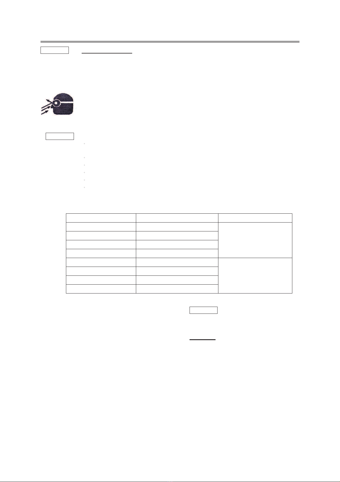
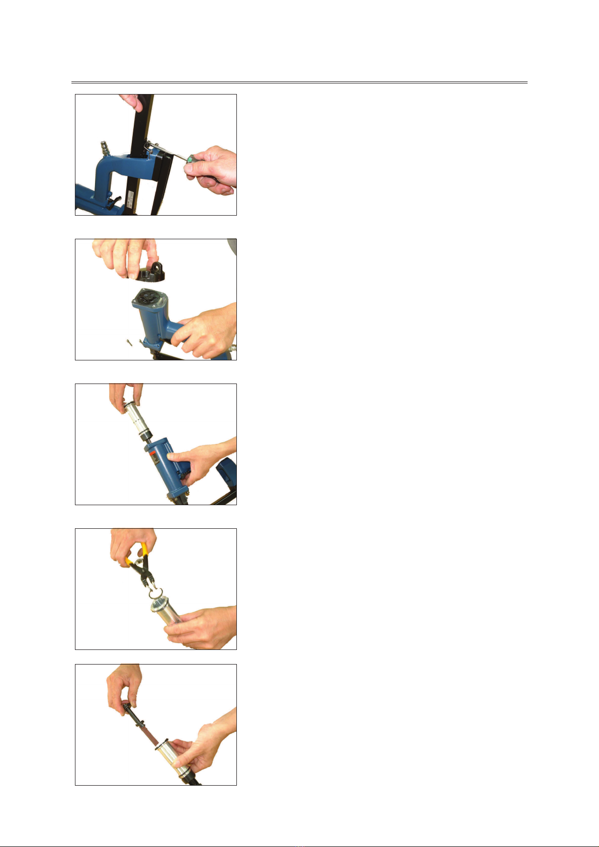
Release Magazine Unit(024).
Release Screw(501) and take away
Cap(001), Packing(002), and
Bumper(003).
Pull out Cylinder Unit(007).
Release C-ring(502).
Take away Driver Piston(004) and
Driver(006).
9
Release the two Screw (512,514)
and take away Anvil (029).
Assemble the new Anvil (029) and
Screws (512,514).
Insert single staple into Driver
Guide(016), leaving points
protruding.
Pull Driver Guide(016) down, until
staple points contact Anvil(029).
Align Anvil(029) with staple points
by turning Screw(506).
When Anvil(029) is properly
aligned, tighten pivot Screw(521)
first, then tighten retaining
Screw(514).
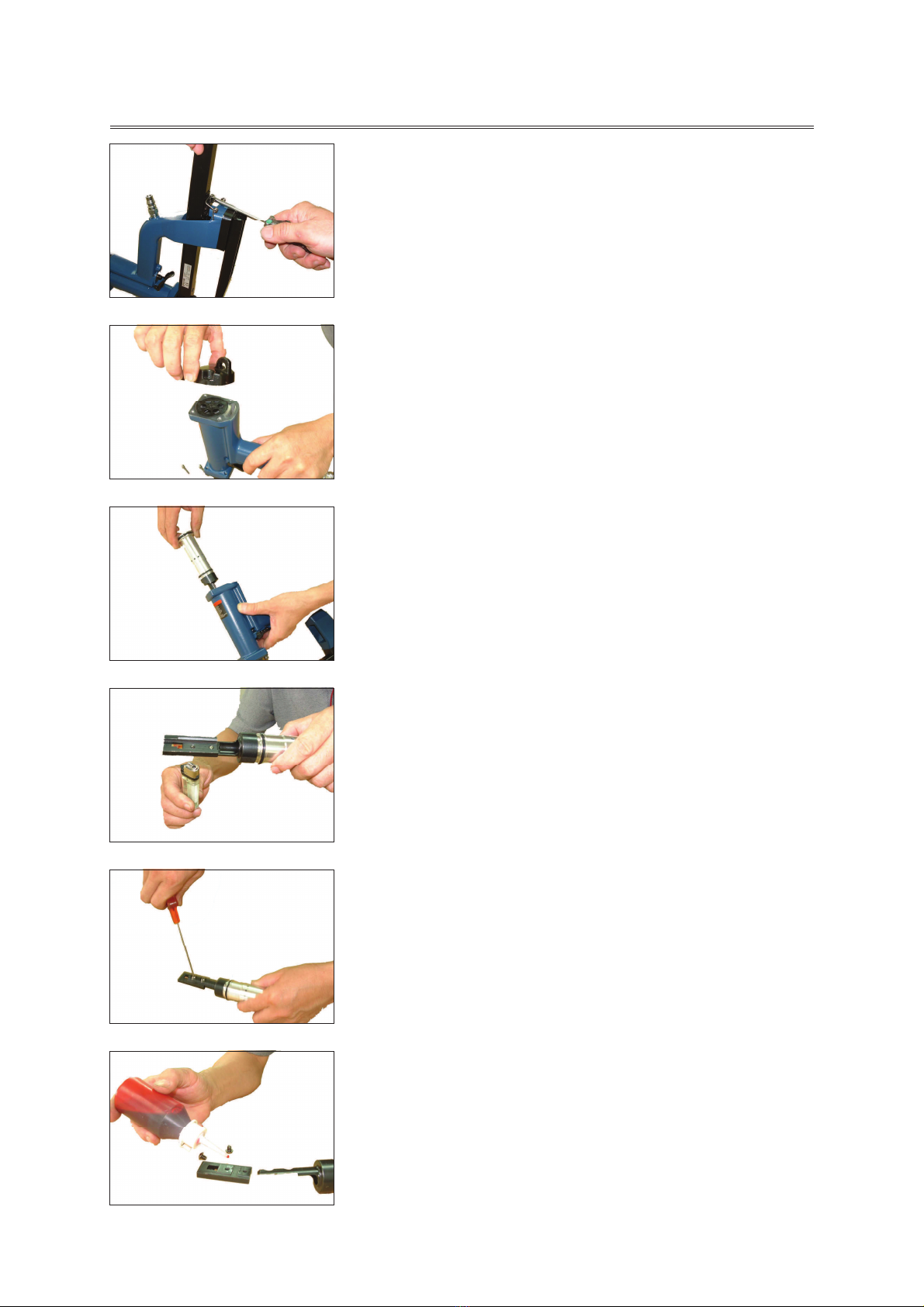
10
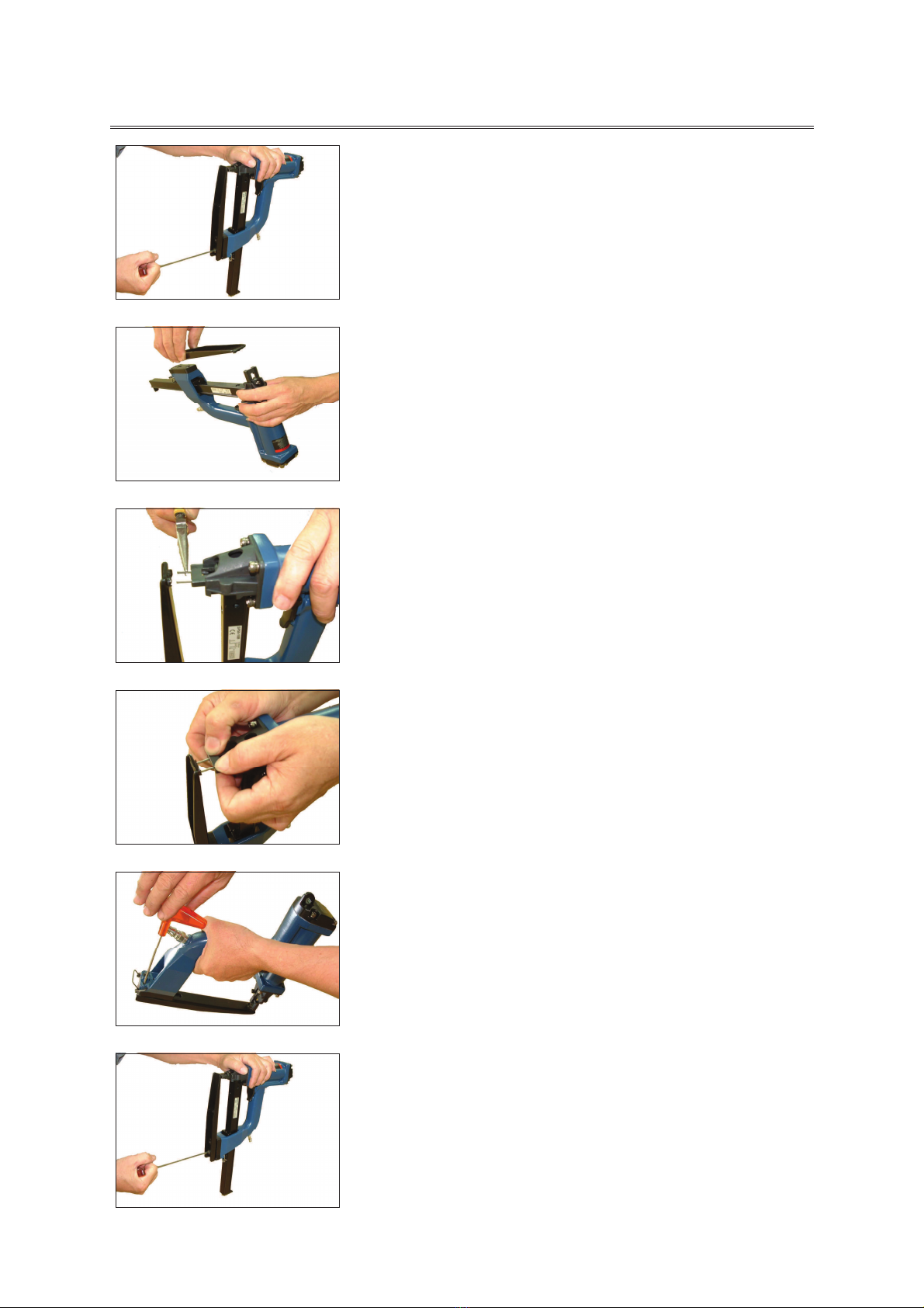
Release Magazine Unit(024).
Release Screws(501) and take
away Cap(001), Packing(002) and
Bumper(003).
Pull out Cylinder Unit(007).
Heat Screws(520).
Release Screws(520) and take
away Driver Guide(016).
Reassemble New Driver Guide (016)
and Screws(520).
NOTE:Use Locktite soluent #75559,
apply Locktite grade 277.

11
Release Magazine Unit(024).
Push Cover Unit(018) forward and
take away Cover Unit(018).
Take away Pusher(019) from top
hole on Magazine(024).
Pull up and take away Block(028)
from Magazine(024).
Separate Springs(022) and
Block(028) by taking away
Rod(025).
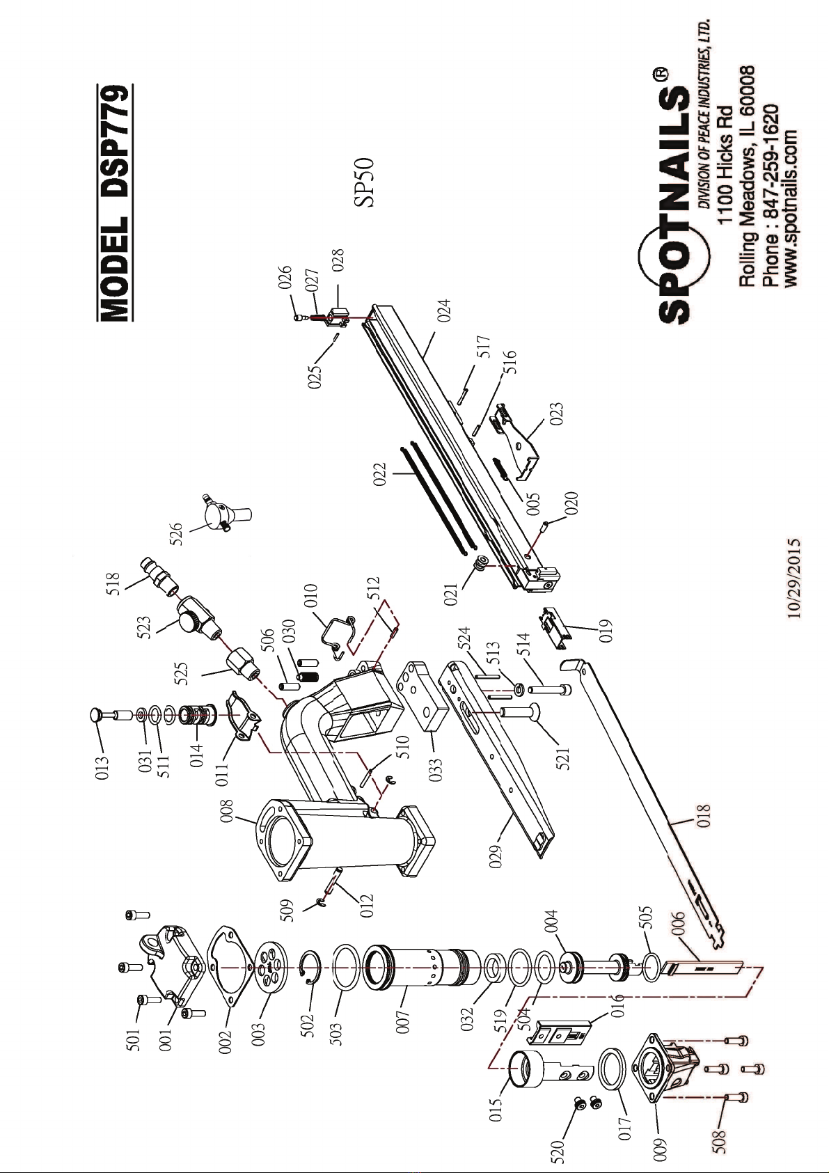
Ref No. Part No. Description Ref No. Part No. Description Ref No. Part No. Description
001
P-60215
Cap
019
P-09237
Pusher
505
P-64576
O-Ring
002
P-63054
Gasket
020
P-07456
Roll Pin
506
P-24580
Set Screw
003
P-15266
Bumper
021
P-20038
Roller
508
P-24576
Socket Cap Screw
004
P-66122
Piston
022
P-18549
Spring
509
P-32284
E-Ring
005
P-18547
Spring
023
P-13114
Magazine Clamp
510
P-07452
Spring Pin
006
P-06285
Driver
024
P-12566
Magazine
511
P-64577
O-Ring
007
P-05126
Cylinder
025
P-07457
Feed Spring Pin
512
P-07453
Spring Pin
008
P-01294
Body
026
P-07450
Lock Pin
513
P-32283
Washer
009
P-08506
Nose-Guide
027
P-18550
Lock Pin Spring
514
P-24582
Socket Cap Screw
010
P-18548
Spring
028
P-13116
Lock Pin Block
516
P-07454
Spring Pin
011
P-21096
Trigger
029
P-31077
Clincher A
517
P-07455
Spring Pin
012
P-07447
Pin
030
P-07451
Pin
519
P-64578
O-Ring
013
P-22220
Plunger
031
P-64560
O-Ring
520
P-24579
Socket Cap Screw
014
P-22216
Trigger Valve
032
P-15267
Bumper
521
P-24587
Socket Cap Flat Head
015
P-06273
Shuttle Sleeve
033
P-03113
Spacer
523
P-43059
Air Flow Control Valve
016
P-06287
Shuttle
501
P-24575
Socket Cap Screw
524
P-07464
Spring Pin
017
P-15268
Bumper
502
P-32285
Retaining Ring
525
P-30122
Air Plug Adaptor
018
P-12556
Magazine Cover
503
P-64561
O-Ring
526
AS-97412
Compact Pressure
504 P-64562 O-Ring Regulator 50 Psi
Parts included in AS-97270 O Ring & Seal Kit
Ver. 01/20/2017
SPOTNAILS MODEL DSP779


CLINCHER B
Part No.
Description
029
P-31082
Clincher B
033
P-03113
Spacer
506
P-24580
Set Screw
514
P-24582
Socket Cap Screw
521
P-24587
Socket Cap Flat
Head Screw
524
P-07464
Spring Pin
CLINCHER CL
CLINCHER CR
Part No.
Description
Part No.
Description
029
P-31072
Clincher CL
029
P-31073
Clincher CR
034
P-31083
Anvil
034
P-31083
Anvil
506
P-24581
Set Screw
506
P-24581
Set Screw
514
P-24583
Socket Cap Screw
514
P-24583
Socket Cap Screw
515
P-24585
Socket Cap Screw
515
P-24585
Socket Cap Screw
521
P-24588
Socket Cap Flat Head
521
P-24588
Socket Cap Flat Head
Screw
Screw
524
P-07465
Spring Pin
524
P-07465
Spring Pin
CLINCHER DL
CLINCHER DR
Part No.
Description
Part No.
Description
029
P-31075
Clincher DL
029
P-31074
Clincher DR
033
P-03113
Spacer
033
P-03113
Spacer
034
P-31083
Anvil
034
P-31083
Anvil
506
P-24580
Set Screw
506
P-24580
Set Screw
514
P-24584
Socket Cap Screw
514
P-24584
Socket Cap Screw
515
P-24586
Socket Cap Screw
515
P-24586
Socket Cap Screw
521
P-24589
Socket Cap Flat
521
P-24589
Socket Cap Flat
Head Screw
Head Screw
524
P-07466
Spring Pin
524
P-07466
Spring Pin
Ver. 11/25/2015
ADDITIONAL CLINCHERS
Table of contents
Other Spotnails Nail Gun manuals


