Powermat PM-OPS-14 User manual

USER MANUAL
SPRAYER / COMBUSTION SPRAYER
PM-OPS-14 / PM-OPS-20 /
PM-OPS-26
ORIGINAL MANUAL

TABLE OF CONTENTS
USER MANUAL................................................ .................................................. ............................ 1
WARNING / INFORMATION SYMBOLS .............................................. ........................................... 3
PURPOSE OF THE DEVICE ................................................ .................................................. ............... 3
MAIN FEATURES OF THE DEVICE ............................................... .................................................. ............... 3
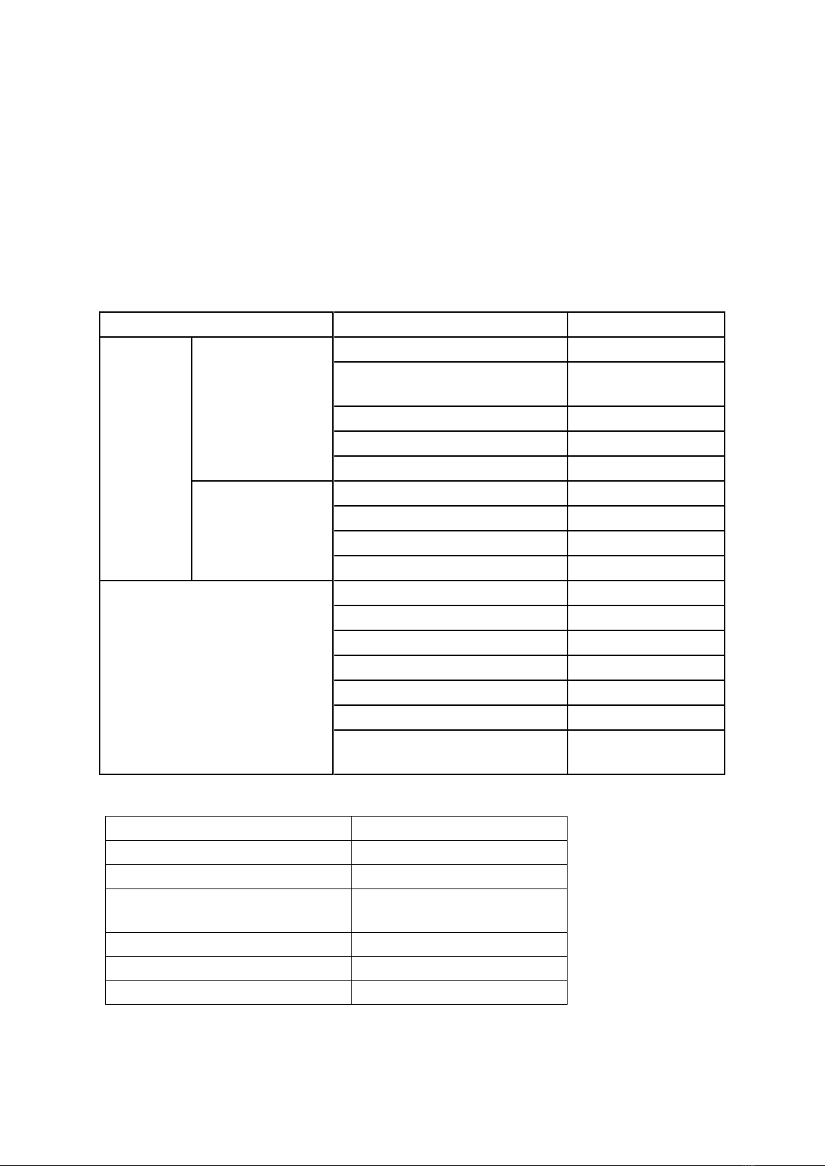
TECHNICAL DATA ................................................ .................................................. ................................ 4
ASSEMBLY ................................................. .................................................. ............................................... 4
Sprayer mode ................................................ .................................................. ............................. 4
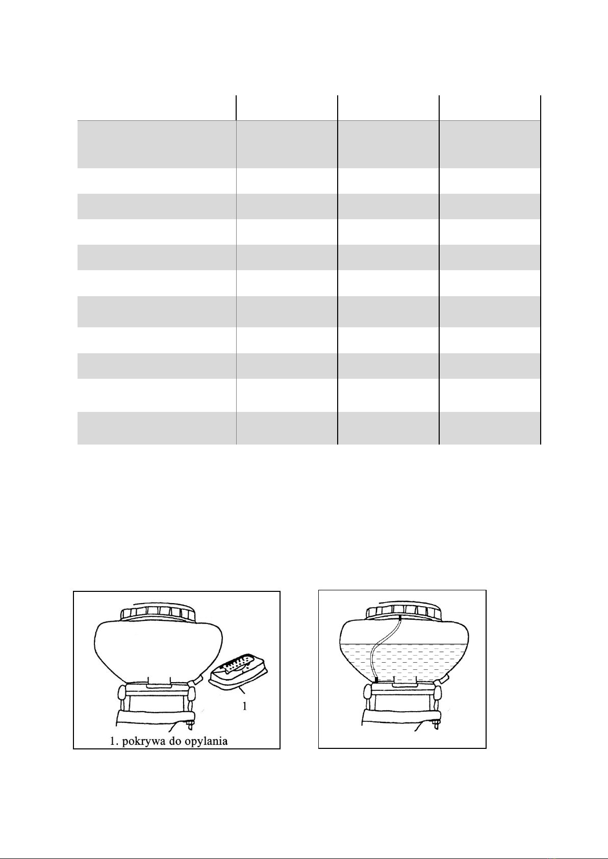
Dusting (spreading) mode ............................................. .................................................. ................. 5
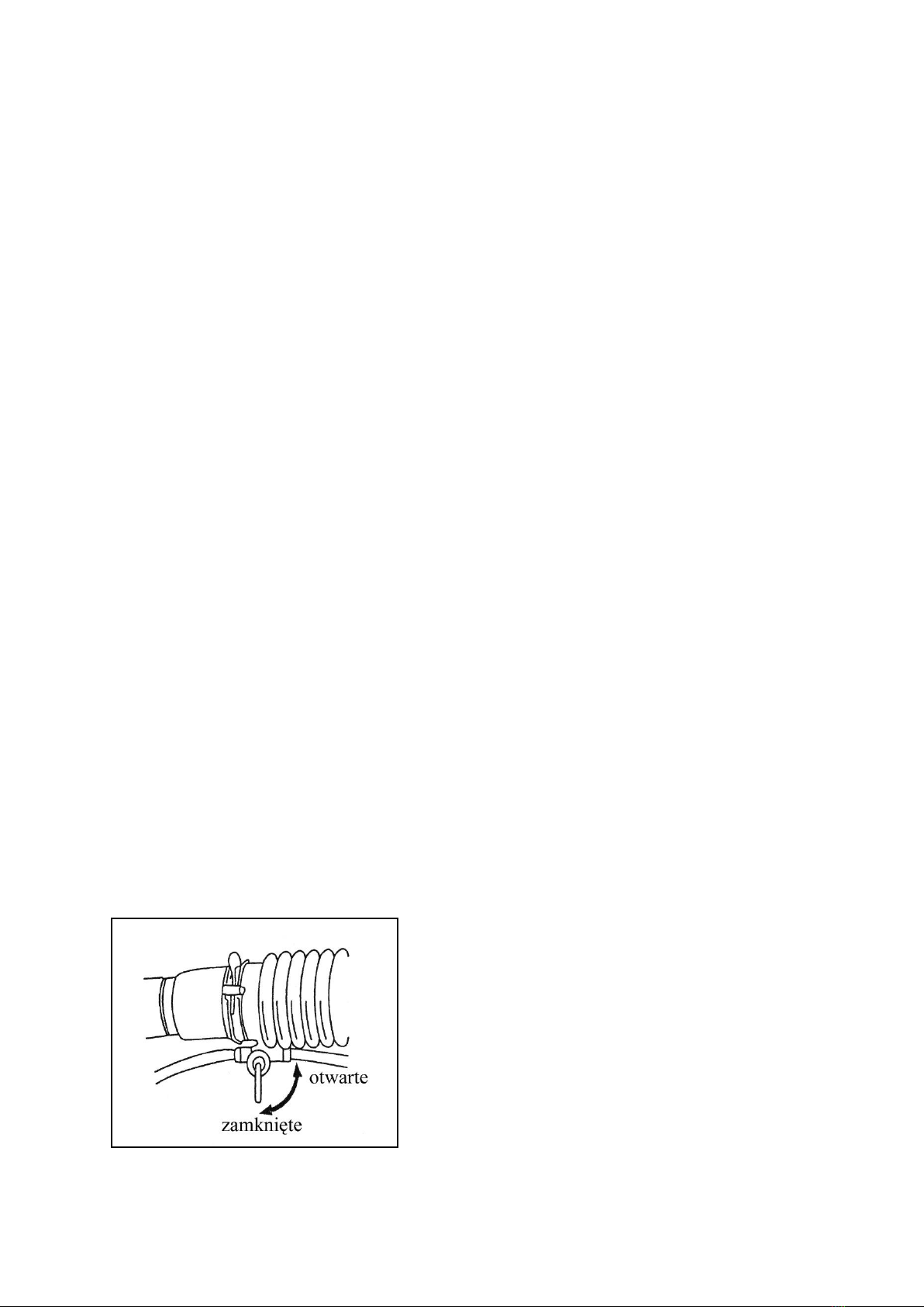
Antistatic installation ................................................ .................................................. ......... 6
USE ................................................. .................................................. ..................................... 6
Adding fuel ................................................ .................................................. .............................. 6
Adding chemicals ................................................ .................................................. ................... 6
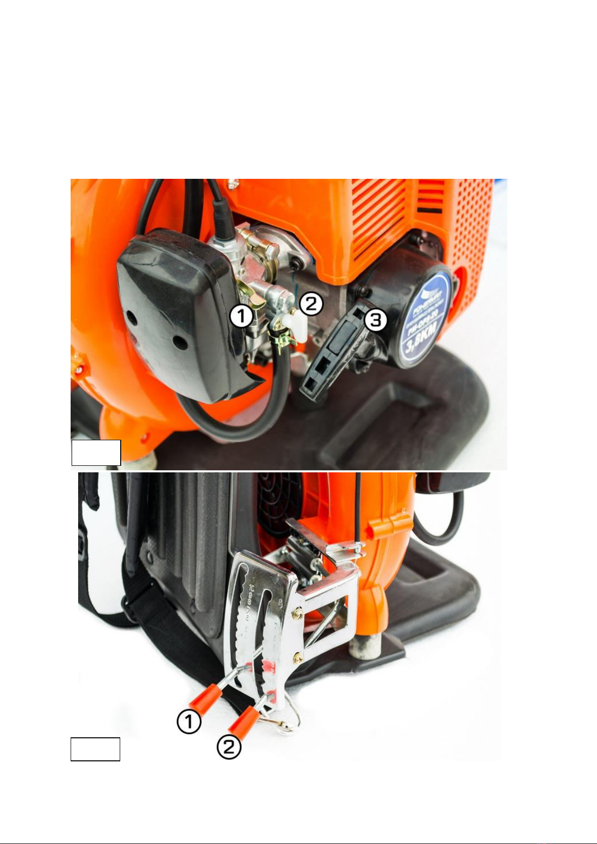
Starting a cold engine ............................................... .................................................. ................... 7
Starting a warm engine ............................................... .................................................. ............ 8
Setting the rotation speed ............................................... .................................................. .......... 8
Stopping the engine ................................................ .................................................. ....................... 8
SPRAYING / SPRAYING (SPREADING) ............................................. ................................................ 8
SAFETY RULES ................................................ .................................................. ................... 9
SOLVING COMMON PROBLEMS ............................................... ........................................ 10
Maintenance and preparation for longer storage ............................................ ......................... 11
DISPOSAL OF USED DEVICES ............................................... .................................................. ....... 12
MANUFACTURER'S DATA ................................................ .................................................. ............................ 13
DECLARATION OF CONFORMITY................................................ .................................................. .................... 13
2

WARNING / INFORMATION SYMBOLS
ATTENTION: Before using the device, carefully read the instruction manual and safety
recommendations. Keep the instructions.
ATTENTION: The use of eye protection is recommended.
ATTENTION: Hearing protection is recommended.
ATTENTION: The use of a dust mask is recommended
PURPOSE OF THE DEVICE
Backpack petrol sprayer is a portable, flexible and highly effective tool for working in plant protection. It can be used
in the prevention of plant diseases and pest control in large plantations and crops of cereals, gardens, flowers, fruit
and tea trees, etc. The device is suitable for use in mountainous, hilly and other types of terrain.
MAIN FEATURES OF THE DEVICE
1. Most parts of the device are made of plastic, which makes the machine light
2. The parts of the device that come into contact with acid are made of reinforced plastic or stainless steel, which prevents
corrosion and ensures a long service life of the device.
3. The opening of the tank has large diameters, which facilitates its filling.
4. The center of gravity of the device is low, which makes the device very stable.
5. Protective structures insulate hot parts of the device.
6. Rotary connection of the hose to the housing facilitates use and ensures a long service life.
3

TECHNICAL DATA
MODEL PM-OPS-14
Liquids:
Powder / Granulate: ≥ Powder / Granulate: ≥ Powder / Granulate: ≥ 6m
6m 6m
≥12m ≥12m ≥12m
PM-OPS-20
≥4m Liquids:
PM-OPS-26
≥4m Liquids: ≥4m
PERFORMANCE
SPRAY / SPRAY
HORIZONTAL SPRAY RANGE
START manual manual manual
ROTATION 7,500 rpm 7,500 rpm 7,500 rpm
ENGINE POWER (STARTING) 3.8KM 3.8KM 3.8KM
MOTOR TYPE
PROPORTION
GASOLINE / OIL
TANK CAPACITY
Two-stroke Two-stroke Two-stroke
MIXTURES 1:25 1:25 1:25
14L 20L 26L
NET WEIGHT:
LEVEL
ACOUSTIC L PA
SOUND POWER LEVEL
10.5 kg 11kg 12kg
PRESSURE
60dB (A) 60dB (A) 60dB (A)
100dB (A) 100dB (A) 100dB (A)
L. WA
ASSEMBLY
Sprayer mode
1.
then reattach and tighten the reservoir. (fig. 1) - (The machine is factory-fitted with the spray cover).
Loosen the screws and remove the reservoir. Replace the dust cover (spreader) with a spray cover
Picture 1 Fig.1a
4

2.
which is connected to the rubber tube (don't forget to put on the rubber gasket). Connect the transparent rubber tube to
the tank cover (Fig. 1a), in this way the turbine air will be forced into the tank, creating an overpressure that will displace
the liquid from the tank through the exhaust hose.
Tank assembly. Remove the bottom cover of the tank and put on the pressure (spray) cover,
3.
to the tank outlet.
Install the nozzle to the device as shown in (Fig. 2), connect the rubber hose
Fig. 2
Dusting (spreading) mode
1.
(Fig. 3) with dust cover (Fig. 3a)
Remove the tank, inlet and outlet tube, spray cover and install the dusting tube
Fig. 3
Fig. 3a
5

Antistatic installation
1.
factors such as type of chemicals, air temperature, humidity. To prevent this from occurring, use the supplied ground
wire.
Dedusting can cause electrostatic charge, it depends on such
Insert one end of the hose into the blow-off pipe while the other end is touching the ground. Connect the other end with
the conductive wire, then screw the conductive wire and the ground wire with screws to the pipe to be bent.
USE
Check it out
1. The cooling hole is not clogged
2. The air filter is not dirty
3. Whether the gap in the candle is 0.6-0.7mm
4. Pull the starter 2-3 times to check that the motor is working properly
Adding fuel
1. Fuel can only be added when the engine is turned off
2. The fuel to oil ratio should be 1:25
3. When refueling, a petrol filter must be installed
Adding chemicals
1.
from the blower, the blower throttle valve and the fuel supply tap should be closed.
When spraying, close the inflow before adding chemicals (Fig. 4). In mode
Fig. 4
6

2.
until the outlet is blocked.
Chemicals should not be in the tank for long periods as this can lead to it
3.
powdered chemicals, clean the tank mounting bolts, and then tighten the cover firmly.
Keep the tank cover tight while spraying. After adding
Starting a cold engine
Fig. 6
Fig. 6a
7

1.
2.
3.
Open the fuel tap on the carburetor (Fig. 6) - 2 Set the choke
lever (Fig. 6) - 1 in the upper position
Set the dusting control lever (Fig. 6a) - 1 in the lowest position, and the engine throttle lever (Fig. 6a) - 2 slightly above the
middle of the range, position 5 or 6.
Pull the starter rope lightly (Fig. 6) - 3, feel resistance, and then pull vigorously until the engine fires.
When the engine starts, move the choke lever (Fig. 6) - 1 all the way down.
4.
5.
Starting a warm engine
1. Turn off the choke
2.
the engine according to the steps in the point "starting the cold engine"
If the engine does not start, shut off the fuel supply and pull the starter 5-6 times then start
Setting the speed of rotation
1. By means of the extreme engine throttle lever (Fig. 6a) - 2, the engine speed can be regulated.
Stopping the engine
1. When spraying, turn off the chemicals first, then turn off the engine
2. In dusting mode, turn off the fuel tap and blower switch
SPRAYING / DRAINING (SPREADING)
1.
regulate the engine revolutions with the lever (Fig.6a) - 2.
Spraying: Adjust the fluid flow through the tubing (Fig. 4) to set the blowing force
2.
(Fig.6a) - 1, in order to set the blowing force, adjust the engine speed with the lever (Fig.6a) - 2.
Dusting (spreading): Use the lever to regulate the atomizing capacity
3.
spread of chemicals
You can use the device in cool weather and light winds. This ensures low evaporation and
4. The sprayer should move against the wind
5.
contact your doctor.
If chemicals come into contact with the eyes or mouth, rinse them with running water and
6.
quit work and contact your doctor
If the operator experiences a headache or dizziness, he should
7. Strong acids and bases must not be used.
8

SAFETY RULES
Please read the instructions carefully. Make sure you understand how to use the machine before starting work.
Protective clothing
1. Wear a brimmed hat
2. Wear safety glasses
3. Wear a protective mask
4. Wear long gloves
5. Wear a chemical protective jacket
6. Wear shoes
The following persons may not use the sprayer
1. Mentally ill
2. Persons under the influence of alcohol
3. Minors or the elderly
4. People unfamiliar with the operation of the device
5. Tired
6. Not sleepy or after a lot of physical effort
7. Breastfeeding and pregnant women
Fire prevention
1. Do not smoke near the device
2. Do not add gasoline while the engine is running
3. Do not spill fuel on the device and clean the device if this happens
4. Always tighten the fuel tank cock
5. Do not turn on the device near fuel tanks
9

Starting the engine
1. Close the flow of chemicals
2. It is impossible to stand in front of the nozzle
SOLVING COMMON PROBLEMS
Heavy engine starts or won't start. Check that the candle is working properly
Problem
No spark
Cause
Water has entered the plug pipe. Electrode
gap too small / too large
Solution
Dry the pipe
Set candle spacing to
0.6-0.7mm
Replace the candle
Clean the spark plug of carbon.
Replace the spark plug
Replace or repair
Replace
Replace
Pass
Reduce the amount of fuel
Change fuel
Contact the fuel. Push down on
the candle pipe
Add fuel
Clean the filter
A pipe of a candle
Broken spark plug insulation
Charcoal on the candle
Burned poles
Cable insulation damaged
Bad coil insulation
Coil wire is faulty The controller is
faulty
Fuel consumption too high
Poor quality fuel
Piston ring and cylinder worn. Spark
plug is too loose. No fuel
Dirty filter
Venting hole in the cap Detect the fuel hole is plugged
The sparker
There is a spark
Low engine power
Cause
Clogged filter
Water in the fuel mixture
Engine overheated
Solution
Clean the filter
Change fuel
Turn off the engine and let it cool
down
Clean the muffler
Change the oil
Change fuel
Carbonized muffler
Bad oil
Bad fuel
10

The engine stops
Problem
The engine cuts out suddenly
Cause
Loose spark plug cable The fuel
has run out
Clogged carburetor
Clogged fuel tank opening. Unplug fuel mixed with
water Change fuel
Solution
Connect the cable securely
refuel
Clean the carburetorThe engine cuts out gradually
Spraying
Problem
No release of chemicals
Cause
Clogged nozzle or nozzle valve
Clogged delivery tube Clean chemical tube
Solution
Clear clogged components
Leakage of a chemical mixture Cover
incorrectly mounted
down spraying. Reinstall the cover correctly
Dusting
Problem
No dusting
dusting
or uneven Powder exit cannot adjust Adjust the dust exit lever
open
Contaminated
powder / granules
Lumpy powder / granules
Wet powder / granules
correct Dust outlet does not close
Dust outlet is blocked Clean the dust outlet for foreign objects
Powder / granules come out The dust cover clamp is in. Press the clamp off the hopper
loose
Damaged lid seal Replace the dust seal
Level Unable to control Powder / granulate
discharge damaged controlling
powder / granules
Dust output no it works
Cause Solution
Clean the powder / granules
Crush the powder / granules
Dry the powder / granules
Adjust the dust outlet jack
device Repair device
exit
Maintenance and preparation for extended storage
Maintenance of spray components
1. Thoroughly clean the sprayer tank after spraying
11

2. Thoroughly clean the sprayer tank and powder / granulate outlet after dusting
3. After work, loosen the tank cover
4. After cleaning the device, run the engine at low speed for 2-3 minutes
Maintenance of the fuel system
1. Gasoline residues in the carburetor may adversely affect the operation of the fuel system and engine operation, after
using the device for a week, drain all the gas from it.
Maintaining the air filter and spark plug
1. Clean the air filter after work
2. The gap between the spark plug electrodes should be 0.6-0.7mm. Check that the gap between the electrodes is
correct and adjust it if necessary
3. Always check the spark plug model of the appliance. Do not use any other candle models
Preparation for long-term storage
1. Clean the device. Coat metal parts with oil or other anti-corrosive substance.
2. Remove the pipe from the candle. Pour 15-20 g of two-stroke oil into the cylinder. Set the plunger to the top position and then put
the plug on the spark plug
3. Remove the tank and clean it thoroughly, then mount it on the device
4. Clean the spraying system thoroughly
5. Drain the fuel tank and clean the carburetor of fuel
6. Cover the machine and leave it in a dry, clean place
DISPOSAL OF USED DEVICES
At the end of its useful life, this product must not be disposed of with normal household
waste, but should be taken to a collection point for the recycling of electrical and electronic
devices. This is indicated by the symbol on the product, manual or packaging. Thanks to
the reuse, use of materials or other forms of using used devices, you make a significant
contribution to the protection of our environment.
12

MANUFACTURER'S DATA
PH Powermat TMK Bijak Sp. Jawna Ul.
Obrońców Poczty Gdańskiej 97 42-400
Zawiercie
DECLARATION OF CONFORMITY
13

Scheme
14
This manual suits for next models
2
Table of contents
Other Powermat Paint Sprayer manuals