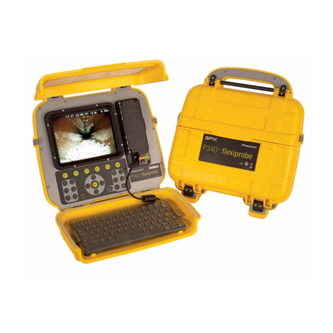
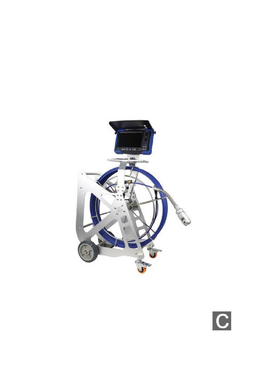
SPX PEARPOINT P350 User manual

P350 flexitrax™system
User guide
Gebruikershandleiding
用户指南
90/UG080INT/03

32
P350 flexitrax™system user guide
This user guide is intended for use with P350 Controller software
versions 4.30 and above. For earlier software contact your local
Pearpoint representative for older versions of the manual. The
P350 flexitrax is a fully modular system; the command module can
drive any combination of drums, cameras and crawlers and is also
compatible with the P340 flexiprobe™range of pushrod reels and
cameras.
This user guide is intended as a compact version of the full operation manual
for quick reference. A full operation manual is provided as a computer file with
your system purchase. The latest version can also be downloaded from
www.pearpoint.com, or contact your local Pearpoint representative for a copy.
Full instructional and safety information on a variety of subjects is covered in the
Operation Manual.
ENGLISH 3
NEDERLANDS 41
中文 81
ENGLISH

54
Safety
A risk assessment should be performed prior to commencing work
as it may highlight additional safety issues specific to the application. This
equipment is NOT approved for use in areas where hazardous, explosive or
flammable gasses, liquids or solids may be present.
The P350 flexitrax, including components, are heavy. If available, use
the wheels to assist transport. Observe heavy-lifting safety practices when
lifting any component of this system. Refer to the system specifications for a
description of the system dimensions and weight.
If mains operated equipment is connected to the system then the external
equipment must be earthed in accordance with the manufacturer’s instructions.
Failure to comply with this may cause the unit to become live and a
LETHAL HAZARD.
The flexitrax Power Supply Unit (PSU) is designed to reduce hazards
from electric shock provided that proper operating procedures are followed.
The P350 flexitrax system requires connection to a protective earth. It is
also recommended to use a residual current circuit breaker (RCCB) that can
protect against electric shock. RCCB devices are known in some countries as
Ground Fault Circuit Interruptors (GFCI). The RCCB needs to be suitable for a
load of 13A and a tripping sensitivity of 30mA or less.
Crush hazard. Never place hands, clothes or foreign objects into the
mechanism of the powered elevator.
Foul water systems can be a source of serious biological hazards. Wear
appropriate protection when handling the P350 flexitrax.
Cameras and lightheads will get hot during use. This is normal.
Exercise care when handling the camera at all times.
System components must NOT be connected/ disconnected when the
power is on. When downhole equipment is not connected, turn off all power.
Never touch live connectors, cable or system internal components without
suitable electrically insulated gloves for high-voltages.
The external connectors of the P350 Manual PSU unit and Powered Drum
are required to be properly sealed by the blanking caps provided or by using the
correct leads to prevent water damage to the units. Under no circumstances are
these connectors to be left un-blanked.
Care must be exercised when operating the drum that the hands, body
and loose clothing are kept well clear of the cable entry area. The cable entry
should not be used as a step and feet kept clear of this area.
Copyright statement
© 2017 Radiodetection Ltd. All rights reserved. Radiodetection is a subsidiary of SPX
Corporation. Radiodetection, Pearpoint, flexitrax, flexiprobe, FlexiSight and RD7100
are either trademarks of Radiodetection in the United States and/or other countries.
Due to a policy of continued development, we reserve the right to alter or amend any
published specification without notice.
This document may not be copied, reproduced, transmitted, modified or used, in whole
or in part, without the prior written consent of Radiodetection Ltd.
The Bluetooth word, mark and logo are registered trademarks of Bluetooth SIG, Inc.
and any use of such trademarks by Radiodetection is under license.
Windows is a trademark of Microsoft Corporation, all rights reserved.
Other trademarks or registered trademarks mentioned in this document belong to
their respective owners.
Any third-party products (including hardware, software and services) mentioned
in this manual are for instructional purposes only and is not an endorsement by
Radiodetection Ltd, Pearpoint and SPX Corporation.
Radiodetection Ltd does not accept any liability for loss of data or damage to
equipment when using any third-party products.
General warning symbol.
Electrical hazard.
Crush hazard exists.
Heavy object. Take care when lifting and obey general manual
handling precautions.
Biohazards. Unsanitary conditions. Consider safety precautions
and strict cleaning.
Hot surface. Caution required during handling and around
flammable/explosive substances.
WARNING! Red warnings alerts possible personal injury scenarios.
CAUTION: Orange cautions alert possible equipment damage.
NOTE: Blue notes contain useful information.

76
Always use heavy duty industrial gloves when handling cable which is
being withdrawn from a sewer.
The controller display module has a waterproof seal flap protecting the I/O
sockets – this must be closed in wet conditions to ensure it is rainproof. Do
not use large USB memory drives that may prevent this waterproof door
from closing – or you may incur water damage not covered by your warranty.
Never clean your system with a pressure washer.
On downhole equipment, a modified screw is used to ensure waterproof
connections. It is critically important that only screws provided by Pearpoint are
used, to ensure waterproof and reliable connection. Significant damage and
costs will occur if “off-the-shelf” screws are used.
Take care to ensure that video and power cables do not get entangled in the
drum. Cables ties are recommended and will not impede system performance.
Always store the P350 flexitrax system in a clean and dry environment.
Ensure that standard safety precautions for working in hostile environments
are followed.
Electrical equipment is factory tested for electrical safety. Routine inspection
is recommended (and may be required by law) to maintain this level of
protection. If you are unsure, contact your local safety authority for advice.
The flexitrax Power Supply Unit has a number of ventilation slots around
the casing that are designed to maximize air circulation and reduce heat.
There is a potential fire risk if the build-up of heat is prevented from escaping.
Under no circumstances are these ventilation slots to be covered or blocked.
An inverter-style generator is necessary to power this system, see the operation
manual for full details on suitable generators and power requirements.
If using a generator follow the manufacturer’s instructions on load connection
and sequencing. In the absence of these instructions the following guidelines
should be used:
• When starting the generator; ensure that all electrical loads, including the
P350 are switched off before starting the generator. Allow the generator to
stabilize before connecting any electrical loads or switching on the P350.
• When stopping the generator; ensure all electrical loads, including the
P350 are switched off before stopping the generator.
• Starting or stopping a generator whilst the P350 system is connected and
the main switch is in the On position could lead to damage to the P350
system or the generator.
A portable generator can be a hazard if not properly operated. Always
follow the manufacturer’s instructions.
Always transport a generator with the minimum amount of fuel in the
tank.
Always switch the system on and off using the main system switch.
If using an invertor to power the system, a good quality full sine-wave model
should be selected. Quasi-sine wave invertors are not recommended for use
with this product.
Never lower crawlers or other heavy equipment into manholes while
personnel work in the manhole.
The camera’s LEDs are very powerful. Do not look directly at the LEDs or
point them at other people.
Caution must be taken when conducting any pipeline or draining system
inspection. Please observe all safety warnings located in the Preface and
throughout this operation manual.
Before you attempt to operate the P350 flexitrax system, it is recommended
that you familiarize yourself with any additional health and safety
requirements that may be defined by company policy and any applicable local
or national laws. Contact your company’s or local government’s health and
safety officer for further information.
It is recommended that an Residual Current Circuit Breaker is used with the
P350 system. Such a circuit breaker may be incorporated into the supply
such as at a generator panel or a standalone unit.
There are no user serviceable components on the P350 system.
Unauthorised repairs may void the product warranty.

98
P350 exitrax command module
1.1 Command module
The command module acts as the controller and digital video recorder and
playback device. Video is displayed on an 8" industrial LCD. Video, pictures and
inspection reports are stored on a compatible high-speed memory card.
reports and pictures. Most stored
files can be viewed or played on the
command module or transferred to
PC. Also used to store and upload
firmware upgrades.
11. Keyboard Socket: Connects the
keyboard.
12. Audio Socket: Connects the optional
headset to record audio over videos.
13. USB-A socket: USB slot for
recording video, pictures, report
information. Can also be used to store
and upload firmware upgrades.
14. USB-B Socket: USB connection to
transfer files to computers.
15. (Optional) Internal battery lead, this
dual-use cable is used to charge the
internal battery, or plugs into item 9,
to power the controller when the
battery is charged.
16. Ethernet RJ-45 socket: Connects to
a PC running compatible reporting
software.
17. Crawler joystick. Controls crawler
speed and steering. Buttons control
elevator height
18. Camera joystick. Controls camera
pan and rotate. Buttons control
camera focus.
19. Battery test: press to check battery
charge level (when on-board battery
is fitted).
1. On/Off Switch. This switch only
works when the unit is powered by
a DC source connected to the power
socket.
2. Keypad and function keys: Allows
the operator to control the system,
select functions and edit text entries.
3. Keyboard: Provides enhanced text
entry capabilities and shortcuts to
access system functions.
4. Display: LCD Screen shows video,
images and various on-screen system
information.
5. Link Cable Socket: Connects to
a pushrod reel, powered drum or
manual external PSU.
6. Command Module support clamp:
Mount the command module onto
the Drum support bracket or to the
optional vehicle wall-mounting kit.
7. Fuse holder: 5 x 20mm T3.15A 250V
cartridge fuse.
8. RCA Video Jacks: Provide secondary
input and output options for external
composite video equipment.
9. Power Socket: DC power input from
vehicle supply, battery options or
mains adapter. For use with pushrod
reels or as a standalone unit.
10. Compact Flash card slot: The
command module uses a Compact
Flash card to store video recordings,
1
12
3
19
4
11
7
2
8
16
9
10
13
14
15
17
18
5
6
Forward
Press down: stop crawler
Press down: return camera to centre
Left Right
Back
Rotate
Pan left Pan right
Rotate
17
18
Section 1 – System overview
The P350 flexitrax is a modular system that is compatible with a variety of powered,
manual drums and pushrod reels. The flexitrax command module can drive any
combination of drums, crawlers and
cameras and is compatible with the
range of P340 flexiprobe pushrod reels
and cameras. The modularity of the system
allows you to create your own solution for
a wide range of deployment scenarios.

1110
1.1.1 Keypad
20. Function keys: Use to select menu
items or activate short cuts.
21. Camera key: Press to take screen
captures.
22. Text key: Press to access the
on-screen text writer menu.
23. Play: Enters the card browser
menu. Starts video playback of
selected file.
24. Pause: Press to pause video
playback or recording.
25. Record: Press to begin a new video
recording.
26. Stop: Press to stop video playback
or recording.
27. Crawler stop: Stops the crawler
moving.
28. Arrow keys: Use for navigation and
to select system parameters.
29. OK: Press to select or confirm
choices in the menu system.
30. LED Brightness/Camera Focus
keys: press to adjust LED
brightness. Fn + Brightness to
adjust camera focus.
31. Rotate/Pan keys: press to rotate the
camera view. Fn + Rotate to pan
left or right. Simultaneous press will
recenter the view.
32. Zoom/Iris – AGC keys: press to
zoom in or out of the camera’s
subject. Fn + Zoom to modify the
Iris and Automatic Gain Control
settings (AGC not available on
Pan, Tilt and Zoom camera).
Simultaneous press will reset the
zoom, Fn + simultaneous press will
reset to automatic iris and disable
the AGC.
33. Function key: Use in combination
with other keys to activate
secondary button functions.
34. Elevator up key: move powered
elevator upward (if fitted).
35. Elevator down key: move powered
elevator down (if fitted).
Command module keypad
20
29
21
22
23
25
26 27
28
35
33
30
31
32
24
34

1312
1.2 Cable Drums
The system supports either a powered or manual drum that can accommodate
cable lengths between 100-305m (330-1000’). The powered drum contains an
integral power supply whilst the manual drum requires an external power supply
unit. Please refer to the Operation Manual for more information.
1.2.1 Powered drum
1. Command module support stand.
2. On/Off switch. Switches the system
on or off.
3. Command module.
4. Reel compartment: Houses up to
305m (1000') of cable wound onto
the drum cassette.
5. Handle bars, wheels and removable
handles: Allow you to manoeuvre
the system easily into position.
6. Emergency stop: Instantly shuts off
system power. When initiated, the
system must be reset.
7. Pushrod connector: Connect and
power compatible P340 pushrod
systems to your P350 controller.
8. Pendant Controller connector, for
joystick/button control of system.
9. Command module connector:
To connect the command module
link cable.
10. Power on/off indicator. A White LED
lights up when the PSU is switched
on and powered up.
11. Power supply socket: To connect
mains power.
12. Fuse holder: 5 x 20mm T12A 250V
cartridge fuse.
13. Crank handle: Will allow the manual
retrieval of the deployed cable.
(Behind side panel).
14. Cable rollers.
1.2.2 Manual drum
15. Cable drum: Houses up to 305m
(1000') of cable.
16. Cable brake.
17. Crank handle socket.
18. Command module support clamp.
19. PSU link cable socket.
20. Manual layering handle: To assist
with laying cable evenly on the drum.
21. Cable rollers.
1.2.3 External PSU (manual
system only)
22. Link cable connection for manual
drum.
Front and rear connection panels (Common to powered drum and external PSU)
9
10 11 12
27
6 8
Manual drum
19
21
20
16
15
18
17
External PSU
22
1
3
4
5
14
5
5
Powered drum with command module installed

1514
Cable deployment rollers
Manhole roller
Downhole rollers
1.2.4 Link cables
Link cables are used to connect
between the P350 controller, drum,
power supply and optionally a P340
pushrod reel.
1.3 Crawlers and cameras
The system is compatible with the P354
small crawler and the P356 medium
crawler. Three interchangeable cameras
can be used. The Forward View (FV)
camera is a fixed, forward view camera.
The Pan & Tilt (PT) camera offers pan
and tilt capabilities and the Pan-Tilt-
Zoom (PTZ) camera offers pan, tilt and
10x optical zoom.
1.4 Elevators
Elevators are attached to the crawlers
and used to position the camera in the
center of a pipe.
Pearpoints range of elevators allow
the crawler cameras to center in pipes
from 4" (100mm) to 36" (900mm). The
powered elevator for the P356 crawler
can be remotely adjusted from the
command module.
1.5 Wheels and spacers
A range of small, medium and large
wheels can be fitted to the crawlers
for centering in different pipe sizes and
materials (see chart overleaf).
Abrasive ‘rasp wheels’ are designed for
use in relined or slippery pipe surfaces,
providing improved traction.
1.6 Pushrod reels and
cameras
The P350 command module is
compatible with the P340 range
of pushrod cameras, which can be
plugged directly into the controller or
plugged into the drum PSU. An adaptor
cable is required to plug pushrod
systems directly into a P350.
1.7 Other accessories
The P350 flexitrax system features a
range of accessories that expand its
functionality and range of applications.
Please refer to the P350 flexitrax
Operation Manual, for a description
of available accessories. Also visit
www.radiodetection.com for a
complete list of available accessories.

1716
533mm [21"]457mm [18"] 610mm [24"]
900mm [36"]
SMALL WHEEL
MEDIUM WHEEL
LARGE WHEEL
305mm [12"] 381mm [15"]
254mm [10"] 305mm [12"]
100mm [4"] 152mm [6"] 203mm [8"] 254mm [10"] 305mm [12"]
OPTIONAL
CRAWLER WEIGHT
305mm [12"
]
381mm [15"
]
152mm [6"]
203mm [8"] 254mm [10"] 305mm [12"] 381mm [15"] 457mm [18"]
P356 CRAWLER (ADJUSTABLE ELEVATOR) CONFIGURATIONS
(305mm [12"] - 900mm [36"] PIPE)
P356 CRAWLER (ADJUSTABLE ELEVATOR) CONFIGURATIONS
(152mm [6"] - 457mm [18"] PIPE)
P356 CRAWLER (FIXED ELEVATOR) CONFIGURATIONS
(305mm [12"] - 381mm [15"] PIPE)
P354 CRAWLER (ADJUSTABLE ELEVATOR) CONFIGURATIONS
(100mm [4"] - 305mm [12"] PIPE)
P354 CRAWLER (FIXED ELEVATOR) CONFIGURATIONS
(254mm [10"] - 305 [12"] PIPE)
NOTE: The PTZ camera
may not be suitable
for use with the P354
crawler, due to a weight
imbalance.
Wheel and elevator congurations Crawler Rasp Wheel congurations

1918
Section 2 – Setup
The P350 flexitrax allows you to configure the system in a number of ways,
depending on which components you have purchased. This section provides
an overview of the setup procedure using the Powered and Manual Drums.
For pushrod instructions, please refer to the P340 flexiprobe Operation Manual.
CAUTION! Before attempting to assemble the system, ensure that the
Powered Drum or the Manual PSU are switched off.
2.1 Assembly
2.1.1 Crawler
You can configure the crawlers with a variety of wheels, cameras and elevators to
suit a wide range of pipes.
Wheels
The P354 is compatible with the 62mm (2.5") and 110mm (4.3") wheel sets, which
can be connected in singular or tandem configurations for deployment in pipes
from 100mm (4")* up to 380mm (15") in diameter.
The P356 is compatible with the 62mm (2.5"), 110mm (4.3") and 170mm
(6.7”) wheels, which can be connected in singular or tandem configurations for
deployment in pipes from 150mm (6") to 900mm (36") in diameter.
A range of specialist wheels are available for advanced users, for instance with
slimmer profiles, gritty abrasive wheels for greasy relined pipes and doubled-up
configurations for additional traction.
Abrasive wheel kits are available for both crawlers, in kits suitable for 6" to 9" pipes
(150mm-225mm). These can give enhanced grip in challenging pipe conditions,
such as greasy or re-lined pipes.
NOTE: Make sure you affix the wheel screws firmly to the crawler body.
*Minimum specified pipe diameter must be maintained along the whole length of the survey.
Cameras
The cameras are simple to attach as they can only be fitted in one way. A single
Allen-head bolt is used to secure the camera’s collar to the crawler’s body.
Elevator
The elevator is used to elevate the camera to help center it in the pipe or conduit
you wish to survey. The elevator is installed between the crawler and camera. The
crawlers are compatible with four elevators:
• Fixed elevator. To deploy the P354 in pipes up to 305mm (12”) and the P356
in pipes up to 381mm (15”).
• Adjustable elevator. To deploy the P354 in pipes up to 381mm (15") and the
P356 in pipes up to 457mm (18").
• P356 large adjustable elevator. To deploy the P356 in pipes from 305mm
to 610mm (12 to 24").
• P356 powered elevator. To deploy the P356 in pipes from 305mm to 900mm
(12 to 36"). This elevator can be remotely controlled from the command
module.
Lighthead
The accessory lighthead provides the camera with more light. With more light you
can deploy the crawler in larger pipes or in pipes made from absorbent material
that would otherwise reduce visibility when inspected with the standard camera’s
LEDs.
The lighthead is fitted between the camera and the crawler or between the camera
and the elevator.
Once you have assembled the crawler, connect it to the cable using the termination
socket at the rear of the crawler’s body.
2.2 Manual Drum and External PSU
The Manual Drum is a light-weight system that can house up to 305m (1000’) of
cable. The Manual PSU connects to the Manual Drum using the link cable.
2.3 Powered Drum
The Powered Drum features a motorized cable reel compartment that can house up
to 305m (1000') of cable.
CAUTION! If you are manually pulling out cable from the powered drum,
take care not to exceed the maximum speed of the crawlers (1.5 ft/sec or
0.5m/s) to reduce the risk of damaging the system.
2.4 Pendant controller
The P350 pendant controller is an
optional accessory which allows you to
control system functions.
The pendant controller connects to
the rear panel on the powered drum
or manual PSU.
For detailed instructions on how to use
the pendant controller, please refer to
the Operation manual.

2120
2.5 Command module
2.5.1 Mounting
You can mount the command module to the powered drum using the support
stand. The stand is fitted to the drum chassis and the command module fits on top.
Once fitted to the drum, you can adjust the height of the command module to suit
your preferences of working environment.
If using a manual drum you can mount the command module to the support stand,
which is clamped to the drum carrying handle.
2.5.2 Power, data and video
When using the Manual or Powered Drum, a single link cable supplies the
command module with power, data and video. The link cable socket is located on
the rear side of the command module.
Mount the command module and connect the link cable to the controller terminal
on the Powered Drum or External PSU.
If using the command module with a pushrod system or as a standalone unit, you can
use the on-board battery (P350+) to power the system, or connect the command
module to a suitable DC source using the power socket located on the front
connection panel.
2.6 Starting the system
When the system is correctly assembled, switch it on using the On/Off switch on
the Powered Drum or External PSU.
If you are using a pushrod system or the command module as a standalone unit,
use the On/Off switch on the command module’s I/O panel.
The command module will display a welcome screen with important information.
Note it and press OK to continue.
NOTE: When you power off the system, wait at least 5 seconds before switching
it on again. Failure to do so may cause the command module to lock up.
2.7 On-screen menu
You can interact with the command module using the intuitive on-screen menu.
To navigate the menus use the function and arrow keys. The key is used to
return to the previous screen. Where a selection is required use the or keys
to select the various options. Use the OK key to confirm the selected choice and
return to the previous menu. You can also use the keyboard’s Function, ESC, Enter
and cursor keys to navigate and select options in the menu.
For a complete description of the menu system, please refer to the Operation Manual.
2.8 Getting help
The command module has a built in, context sensitive help screen. To access the help
page press Fn + F1 simultaneously on the keypad or Shift + F1 on the keyboard.
You can also view a list of shortcuts. Shortcuts help make operation of the
system more efficient by saving you time. To see a list of shortcuts press Fn + F2
simultaneously or press Shift + F2 on the keyboard.
For more detailed instructions, please read the Operation Manual.
2.9 Configuration
2.9.1 First use
When first using the system, be sure to set or check the following settings:
NOTE: The system will store your preferences, cable length and wheels when
it is switched off. If you reset the system to factory default, these settings are
lost. To perform a factory reset, please refer to the Operation Manual.
Date and time
If required, enter the correct date and time and choose your preferred format. Setting
this is important as it is used to time stamp video recordings and other important files.
Go to MENU->SETUP->CONTROLLER->BASIC SETTINGS-> Select TIME or
DATE.
Units of measurement
The P350 system supports metric and imperial (US customary) units.
To select your preferred unit of measurement system, go to MENU->SETUP-
>CONTROLLER->BASIC SETTINGS->COUNTER UNITS and select METRIC or
IMPERIAL.
Language
The system supports several languages.
To set your preferred language, go to MENU->SETUP->CONTROLLER->BASIC
SETTINGS->LANGUAGES.
Cable length and drum type
Setting the correct cable length is important to help improve video quality and
calculate crawler and drum speeds. You must check this setting, and change
if required, every time you replace or change the cable reel or switch between
pushrod and crawler-based configurations. You will cause damage to your system if
you select the wrong size of drum/reel/wheels.
To set the cable length and drum type, go to MENU->SETUP->EQUIPMENT->
select REEL and scroll to your drum. You may also select EQ ADJUST which may
improve image quality.

2322
NOTE: If set as a pushrod system, the P350 command module will fail to
work with the crawler system.
Crawler wheel size
You must specify the size of the currently installed wheels as the system uses this
information to calculate the crawler’s speed.
CAUTION! Incorrectly setting the wheel size may compromise the
retrieval process and result in jamming the crawler’s wheel on the cable.
To set the wheel size, go to MENU->SETUP->EQUIPMENT->WHEELS.
Numeric inclinometer
The crawler features an integrated precision inclinometer that provides a real time
numeric reading of the crawler’s body inclination.
The P350 inclinometer supports two units of measurement: Degrees or Gradients.
You should calibrate the numeric pitch before starting a survey, with the crawler in
its final setup (wheels, elevator and elevator height set).
To calibrate the inclinometer, go to MENU->SETUP->MAINTENANCE-
>CALIBRATE TRACTOR NUMERIC PITCH and follow the instructions.
Uneven/worn/uncalibrated wheels may be factors which reduce the accuracy of the
inclinometer or pipe profile mapping.
To turn the inclinometer on or off, go to MENU->SETUP->ON-SCREEN
INFORMATION->PITCH and select ON or OFF.
To change the inclinometer units, go to MENU->SETUP->BASIC SETTINGS-
PITCH UNITS and select Degrees or Gradients.
This can be used with the optional profiling module of our companion software
FlexiSight Manager to survey and map the profile of the pipe.
On-Screen Display (OSD) layouts
The P350 System offers a choice of 3 different layouts for the position of Date,
Time, Counter and Pitch; these layouts are: normal, TV and custom.
To choose a layout or to customize the position or visibility of the OSD information
fields go to the Layout menu: MENU->SETUP-ON-SCREEN INFORMATION.
Select SCHEME to enter the OSD layout menu.
1. Use the and keys to select your desired layout.
2. Press OK to confirm your choice and return to the Layout menu.
Normal layout: This is the standard layout optimised to make use of the entire
screen.
Custom Layout: This layout is customisable. The position of the 4 OSD
information fields can be moved anywhere on the screen.
TV layout: This layout is optimised for a DVD Recorder/TV screen.
Refer to the Operational Manual for more information.
Section 3 – Deploying the crawler
Once the system is correctly installed, you can deploy the crawler in the pipe
or conduit you wish to survey. Care must be taken when deploying the crawler,
particularly if it is being deployed in deep conduits and cisterns.
CAUTION! Do not attempt to lift the crawler by the cable. Do not drop
the crawler as it may damage the camera and the system’s electronics.
WARNING: The crawlers are heavy! Observe proper lifting procedures
when handling, deploying and retrieving the crawler. Never lower tractors
or other heavy equipment into manholes while personnel are working in
the manhole.
3.1 Crawler deployment tool
The crawler deployment tools for the P354 and P356 crawlers are optional
accessories that allow an operator to safely deploy and retrieve a crawler into
manholes, culverts and other access points. Using the crawler deployment tools is
highly recommended.
Refer to the Operation Manual for a detailed guide on how to setup and use the
crawler deployment tools.
3.2 Cable deployment rollers
The optional cable deployment rollers help protect the cable from scoring on
concrete and other abrasive materials. Pearpoint recommends that you always use
cable deployment rollers.
3.3 Distance counter and Auto Stop point
Once you have deployed and positioned the crawler in the manhole you should
zero the distance counter, press F10 on the keyboard to zero the counter.
The zero (0.0) position is used by the powered system to decide when to stop
reversing or retrieving the crawler. You can also set a different stop point called
Auto Stop. The system will stop reversing when this stop point is reached.
To set this limit:
Move the crawler to desired counter position, go to:
MENU > SETUP > EQUIPMENT > and choose AUTO-STOP.
Please note that the Auto Stop position is saved by the system and will be active
until it is reset.
To reset the Auto Stop point:
Zero the counter and set this to become the new Auto Stop limit.

2524
3.4 Activating the sonde
The crawler features an integrated, multi-frequency sonde. This allows you to
locate the crawler’s position using a Radiodetection cable and pipe locator.
To activate the sonde press Fn + F5 on the keypad or shift + F5 on the keyboard.
The sonde frequency can be set or adjusted using the system menu, or the pendant
controller.
Section 4 – Driving the crawler
This section provides instructions for driving and retrieving the P350 crawlers when
used with the manual or powered drum. Although the principle is the same, the
powered drum offers several automated features that make it easy to retrieve the
crawler automatically.
CAUTION! Make sure you have set the correct wheel size before you
attempt to drive the crawler.
4.1 Emergency stop
The Emergency Stop button located on the PSU will completely shut down the
command module and all system components when pressed. As a fail-safe, the
system must be reset before you can switch on the system again. Do not reset the
system until it is safe to do so. To reset the system ensure the power is switched off
at the main switch (item 2 on page 6), rotate the Emergency Stop button clockwise
and then switch the power back on.
NOTE: Initiating an Emergency Stop may result in loss of data on the memory
card, particularly if a recording or playback was in progress.
4.2 System stop
You can stop the drive system, including the crawler and the powered drum at any
time by pressing the Ctrl + C,or .
When controlling the system from the keyboard you can also use the spacebar to
stop the system.
When stopped, the crawler will be in Brake mode. Press the spacebar, Ctrl + C, or
to toggle the Brake.
WARNING! System stop is not a substitute for making an Emergency
Stop. If there is any emergency use the Emergency Stop button located
on the PSU. Please refer to Section 5.1 for more information.
4.3 Driving and the On-screen display
NOTE: If you have selected a Pushrod, ROD will be displayed by the OSD.
The command module’s onscreen display (OSD) will provide you with critical
information, navigation and telemetry assistance as well as pan and tilt camera
controls (if available) using mimic.
Driving OSD includes the following information:
• Mode.
• Status.
• Time.
• Date.
• DVR status.
• Distance counter.
• Page.
• Numeric inclinometer.
• Mimic.
Some information displayed on this screen can be hidden or moved. Refer to the
operational manual for more information.
Driving mode OSD
MENU MAN BRI CONTR
System menu
Mode Status Time Date DVR Counter
Pitch
Mimic
Page number
Page 1

2726
4.4 Mimic
Mimic is an intuitive on-screen feature that helps you control the movements of the
crawler and the position of the camera’s viewing angle (PT and PTZ cameras only).
4.5 Analog joystick control
The left hand joystick provides intuitive control of the crawler.
The front/back axis controls the acceleration of the crawler. The left/right axis
controls the steering of the P356 crawler.
The associated buttons control the elevator position when the powered elevator is
fitted. (See 4.9).
4.6 Manual system
Moving forward using the keypad
NOTE: There is no difference in operation between the Manual or Automatic
mode when moving the crawler forwards.
Press to move the crawler forward. Increase the speed by holding or pressing
. Decrease the speed by holding or pressing .
NOTE: If you continue to press when the crawler has stopped, it will move in
reverse. The crawler will automatically stop when the cable counter reaches 0.0.
Reversing
CAUTION! When reversing or retrieving the crawler ensure that the cable
is retrieved at the same or higher speed than the crawler. Failure to do so
may cause the crawler to get tangled in the cable and stall.
Use the crank handle to retrieve the cable. Use the manual wind layering handle to
ensure the cable is laid evenly in the drum.
You can reverse the crawler in Manual (MAN) or Automatic (AUT). Press F3 to
toggle between Automatic and Manual driving modes.
Manual mode
In MAN mode, the crawler will start moving backwards as soon as it is driven.
Press to reverse the crawler. Increase the speed by holding or pressing .
Decrease the speed by holding or pressing .
Automatic mode
In AUT mode the crawler will not move backwards until it detects that the cable is
being retrieved. Automatic mode is recommended for most situations.
To enable the crawler ensure to be in Automatic mode and press once.
NOTE: The mimic speed bar is disabled in automatic mode. The crawler’s
speed is automatically set to match the retrieval speed of the cable.
The crawler will stop moving if the cable is no longer retrieved.
4.4.1 Basic mimic
The basic mimic display appears when
a P354 crawler is connected to the
system. Basic mimic features an artificial
horizon and a speed indicator that shows
the crawler’s forward and reverse speed.
4.4.2 Steering mimic
Steering mimic is displayed when a
P356 crawler is connected to the system.
In addition to the features of the basic
mimic, steering mimic features a steering
bar that indicates when the crawler is
turning, steering left or right and the
speed at which it is moving.
4.4.3 Pan and tilt camera mimic
Pan and tilt camera mimic is displayed
when a pan and tilt camera is connected
to the system. Pan and tilt camera
mimic provides a two dimensional
representation of a pan and tilt camera’s
three dimensional range of movements.
The mimic cursor, represented by the
square box, acts as a target, which can
be positioned using the following keys
on the keyboard:
• W(up).
• A(left).
• S(go to).
• D(right).
• X(down).
Once you have positioned the cursor on
the desired position, press the S key and
the camera will automatically move itself
to look at the target.
Basic mimic
MENU AUTO BRI CONTR
Steering mimic
MENU AUTO BRI CONTR
Pan and tilt mimic with steering bar
MENU AUTO BRI CONTR

2928
4.7 Powered drum
Moving forward using the keypad
NOTE: There is no difference in operation between the Manual or Automatic
mode when moving the crawler forwards.
Press to move the crawler forward. Increase the speed by holding or pressing
. Decrease the speed by holding or pressing .
NOTE: If you continue to press when the crawler has stopped, it will move
in reverse.
Reversing
NOTE: The crawler will automatically stop when the cable counter reaches
0.0, or when the auto-stop position is reached. However, the crawler’s
momentum may cause it to roll a short distance beyond the 0.0 position.
Please allow for this when you deploy the camera and zero the distance
counter.
The powered drum supports two driving modes: Automatic and Manual. The main
difference is that when reversing in manual mode, the crawler and powered drum
operate independently. Manual driving gives you more control over the crawler
and drum but can increase the risk of jamming the crawler wheels on the cable,
particularly if the crawler reverses over the cable. Press F3 to toggle between AUT
and MAN driving modes.
Press to reverse the crawler. Increase the speed by holding or pressing .
Decrease the speed by holding or pressing .
In AUT mode, the powered drum will automatically retrieve the cable as the crawler
reverses. To avoid the risk of jamming the wheels in the cable, the crawler will
reverse at a slower speed than the cable.
In MAN mode however, the drum will not retrieve the cable and you must
synchronize the speed of the crawler and the cable.
To rewind the cable in manual mode, hold the Fn key and press on the keypad.
Hold this key combination to accelerate the rewind speed.
Decrease the speed by holding or pressing Fn + .
The system will stop reversing when the Auto Stop limit (if set) and the zero point
has been reached.
CAUTION! In manual mode, make sure the cable is retrieved faster than
the crawler speed. This will help to avoid the risk of jamming the cable in the
crawler wheels.
Manual retrieval with the crank handle
If necessary, you can retrieve the crawler using the crank handle to manually wind
the cable back into the drum.
Refer to the Operational Manual for more information.
Cable-only retrieval
In some circumstances it may be convenient to retrieve the crawler at the end of a
survey by detaching it from the cable at the final access point.
To retrieve the cable with no crawler attached, switch the system into Manual mode,
and press Fn + .
4.8 Steering (P356 crawler only)
NOTE: Steering the P356 crawler is identical for both the powered and
manual system.
You can steer the P356 crawler left and right, allowing you to navigate pipes with
ease. The crawler steers by changing the speed on the left or right motor.
You can steer the crawler when it is moving forwards, backwards or when it is
stationary. Steering whilst reversing is possible in manual driving mode only.
Note: Steering whilst moving is proportional to the crawler speed: the faster
the crawler moves the bigger the steer.
When the crawler is stationary, it will turn on its own axis. Be careful when turning
in this fashion as the crawler may become entangled in the cable.
To steer right, press . Hold the key to turn faster.
To steer left, press . Hold the key to turn faster.
You can stop the crawler steering at any time by pressing if stationary or moving
forward or when reversing in manual mode. If the crawler is moving it will stop
steering and continue to move in the same direction.
To stop turning the crawler when it is stationary you can also press or the
spacebar.

3130
4.9 Setting the powered elevator height
Never place hands, clothes or foreign objects into the mechanism of the
powered elevator.
The P356 powered elevator can be used to centre the system camera in the pipe
being surveyed.
The elevator can be controlled by:
Using the dedicated keys on the keypad or the keys or on the left joystick pod to
manually raise or lower the camera.
Pressing F2 and use the and arrows to set the camera to a percentage of
the elevator’s maximum elevation.
NOTE: When reversing the system, it is recommended to set the elevator to
it’s minimum height unless centering is required.
NOTE: in some configurations and pipe materials, steering sensitivity may be
affected at high camera elevations.
Section 5 – Camera controls
The P350 cameras have a range of features to help you locate and analyse faults.
5.1 Analog joystick control
The right hand joystick provides intuitive control of the connected camera.
The left/right axis controls the pan function (see 5.4), while the front/back axis
controls the tilt/rotate function (see 5.5).
The associated buttons control the camera focus – ∞for far objects and o for close
objects.
5.2 Lights
All cameras feature LED floodlights to help illuminate pipes and conduits. LED
brightness is controlled using the brightness controls on the keypad. Press to
reduce or to increase brightness.
If no auxiliary lighthead is used, press the brightness keys simultaneously to toggle
the lights off or switch them on to their previous level.
5.2.1 Auxiliary lighthead
The camera’s LEDs and the auxiliary lighthead can be operated simultaneously or
independently. If a lighthead is connected, simultaneously pressing the brightness
keys will toggle the light controls between the following modes:
• Light control: ALL. Adjust both the camera and lighthead in series.
• Light Control: AUX. Adjust the lighthead only.
• Light control: CAMERA. Adjust the camera only.
When selected, the light control mode will flash on-screen and fade. Use the
brightness keys to adjust the lighting level.
NOTE: When a lighthead is connected you cannot toggle the lights on and
off using a simultaneous press of the brightness keys as this will change the
control mode. To switch off the lights when a lighthead is connected, press
the button until the lights are switched off.
WARNING! The camera and lighthead LEDs are very powerful. Do not
look directly at the LEDs or point them at other people.
5.3 Focus
You can manually adjust the focus of P350 cameras to get a clearer picture of a
defect or point of interest.
To focus in or out of the FV and PT camera’s subject, press Fn key and or .
The PTZ camera features automatic focus. You can adjust the focus manually
using the Fn and or . To resume automatic focus mode press Fn, and
simultaneously.
NOTE: the FV and PT cameras have a focus range of 10mm (½") to infinity.
The PTZ camera has a focus range of 10mm (½") (WIDE) to infinity.
5.4 Pan
When using the PT and PTZ cameras you can pan from side to side, giving a wide
field of vision without having to manoeuvre the whole crawler.
To pan left or right, press Fn and or once to start panning in that direction.
Press either key again to stop the camera panning.
When using the FV camera you can use the pan function to digitally pan a zoomed-
in picture on screen.
To pan left or right, press Fn and or once to pan a fixed step in that
direction.
Press simultaneously Fn, and to reset the digital pan.

3332
5.9 Joint Scan
To perform an automated scan of a pipe joint using a PT or PTZ camera, press ‘J’
on the command module keyboard.
Section 6 – Video and images
6.1 Recording video
The P350 features digital video recording, that captures video from the camera and
stores it as an MPEG4 video file on the memory card.
You can start and stop a video at any time using the video controls on the keypad.
To create a quick video survey: press the Video recording button (bottom left
under the display). Fill in any survey information (can be left blank) and press a
2nd time to start recording (notice the recording icon now displays on the screen).
To create a full JOB, navigate to the JOB Browser menu and create a new JOB.
Fill in all the relevant CLIENT, SITE and SURVEY information and START the JOB
(see the full Operation Manual for furthers details). This will allow a professional
looking survey report to be created quickly in FlexiSight Manager partnered with
Microsoft Word.
If necessary, press F10 on the keyboard to zero the counter at the beginning of the
survey.
Press to stop the recording.
For more information about video recording, please refer to the Operation Manual.
6.2 Audio commentary
You can easily add audio commentary to your videos. To record commentary, simply
attach the optional headset to the connection socket in the command module’s I/O
panel (Item 12). Start recording and speak into the microphone.
6.3 Capturing pictures
You can capture still pictures at any time, during operation, including when you are
recording or playing video files. Captured pictures are stored as JPEG files on the
memory card.
To take a picture, press at any time.
5.5 Tilt or rotate
The PT and PTZ cameras can rotate. When combined with the pan function, you
can survey objects above and below the crawler.
To start to tilt/rotate the video on-screen clockwise press .
To start to tilt/rotate the video on-screen anti-clockwise press .
To stop rotating press either key again.
When using the FV camera you can use the rotate function to digitally rotate the
picture on screen.
Press or once to digitally rotate of a fixed step the picture clockwise or
anti-clockwise.
Press simultaneously and to reset the digital rotation.
5.6 Center
When using the PT and PTZ cameras you can return the camera to the forward
view, leveled position, by pressing and simultaneously.
5.7 Zoom
The P350 system offers digital zoom capabilities when used with the FV and PT
cameras.
The PTZ camera features a 10x optical zoom. The digital zoom is disabled when
this camera is used.
To zoom in on the camera’s subject press .
To zoom out from the camera’s subject press .
To reset the zoom to x1 magnification press and simultaneously.
5.8 IRIS/AGC
On occasion, there may be a requirement for manual control of the iris to change
the picture brightness (e.g. to reduce a reflective glint from a shiny surface).
Manually opening the iris to maximum aperture will allow more light to enter the
camera giving a brighter picture. Closing the iris to the minimum aperture will
decrease the amount of light entering the camera giving a darker picture.
Forward view and pan and tilt (with software version 2.25 or later) cameras offer
Automatic Gain Control (AGC), which once activated allows cameras to be used in
poorer light conditions.
Press the key (Fn and ) to increase the picture brightness or to enable the
AGC, once the widest iris setting has been reached (forward view and pan and tilt
camera only).
Press the key (Fn and ) to reduce the picture brightness.

3534
Section 7 – Text and reports
The P350 allows you to add text pages, for instance to add contact, site or survey
information on to recorded video. These pages can be saved and repeatedly used
for common details.
The P350 features an integrated report writer that allows you to document your
survey with text and pictures. Reports can be created in Microsoft Word when used
with our companion software, FlexiSight Manager. This includes industry standard
WRc and PACP codes widely used worldwide.
Press the to display text pages which appear overlaid on the video during the
intro. Press F1 (EDIT) to edit your text, and press TITLE to turn the page on/off
– this sets the text page to display during the video intro. It will display TITLE ON
when the page is activated.
Alternatively, to write text on the video quickly at any moment, press the PG UP or
PG DN buttons on the keyboard, type the required text and press ENTER or OK to
overlay it on the video (ensure the red video recording symbol re-appears!).
For more information, please refer to the Operation Manual.
Section 8 – Connectivity
8.1 USB
You can connect the command module to your PC using the supplied USB cable
to transfer video files.
For more information, please refer to the Operation Manual.
8.2 Bluetooth®*
The P350 features an integrated Bluetooth module that allows you to send
small files to any compatible device. Bluetooth has limited bandwidth so it’s not
recommended for sending large video files.
Some devices do not currently support the OBEX Bluetooth functionality for file
transfer, including most Apple and Motorola phones.
For more information, please refer to the Operation Manual.
*The Bluetooth word mark and logos are owned by the Bluetooth SIG, Inc. and any use of such mark
by Radiodetection is under licence.
Section 9 – System shortcuts
This P350 command module offers a series of keypad and keyboard shortcuts.
Familiarizing yourself with the shortcuts will allow you to work more efficiently.
You can access a list of available shortcuts by pressing Fn +F2 on the keypad or
SHIFT +F2 on the keyboard.
Miscellaneous commands and shortcuts
Keypad key Keyboard key Description
Fn + F1 Shift + F1 Help
Fn + F2 Shift + F2 List all shortcuts
Fn + F4 Shift + F4 Software versions screen
Fn + F5 Shift + F5 Sonde on/o
Fn + F6 Shift + F6 Jump to top menu (when possible)
F9 Enter counter value
F10 Calibrate / zero counter
H Switch Mimic on /o
Fn + Ctrl + ↑Decrease drum rate of pull
(manual mode only)
Fn + Ctrl + ↓Increase drum rate of pull
(manual mode only)
Crawler commands and shortcuts
Keypad key Keyboard key Description
↑Drive forward
↓Drive backward
←Steer left (P356 crawler only)
→Steer right (P356 crawler only)
Ctrl + C Motion Stop
Alt +
←Lock steer left
Alt +
→Lock steer right
Ctrl +
←Trim left
Ctrl +
→Trim right
M Switch drive mode (MAN / AUTO)
Space- Motion Stop
bar (Drive mode only)

3736
Camera commands and shortcuts
Keypad key Keyboard key Description
F7 Light –
F8 Light +
Ctrl + B Iris close
Ctrl + D Light switch
Ctrl + F Pan reset
Ctrl + G Pan right
Ctrl + H Pan left
Ctrl + I Rotate clockwise
Ctrl + J Zoom reset
Ctrl + K Zoom out
Ctrl + L Zoom in
Ctrl + N Iris open
Ctrl + O Rotate anti-clockwise
Ctrl + T Focus in
Ctrl + U Rotate reset
Ctrl + Y Focus out
W Mimic Target UP
A Mimic Target Left
X Mimic Target Down
D Mimic Target Right
S Mimic Go to Target
J Scan pipe joint
Video commands and shortcuts
Keypad Key Keyboard key Description
Ctrl + A Play
Ctrl + Q Take snapshot
Ctrl + S Pause
Ctrl + W Text
Ctrl + X Video stop
Ctrl + Z Record
Section 10 – Care and maintenance
WARNING! Clean and sanitize the P350 flexitrax system at regular
intervals to help prevent the risk of biological contaminations from foul water
sources.
Do not dismantle component parts, unless directed by the Operation Manual.
Only use Pearpoint supplied parts. Warranty and safety may be void if modifications
are performed.
10.1 Terminals
CAUTION! Do not use damaged, dirty or corroded components, including
all terminal connections, cables and O-rings.
Ensure that all terminals and connection points are clean and free of corrosion and
debris before you attempt to use this equipment.
Check that any O-rings are clean, greased and not damaged. Use a silicon based
grease such as "Super Lube".
Pearpoint recommends protecting all terminals with plastic protection caps when
the system is not in use.
If possible, only assemble or disassemble system components in a dry and clean
environment.

3938
10.2 Cleaning the system
WARNING! Foul water systems can be a source of biological hazards;
ensure you clean all equipment with a suitable disinfectant after use.
CAUTION! Do not use high-pressure hoses to clean this system.
10.2.1 Command Module
• Clean the case with mild soapy water.
• Use lint-free cloth to clean the TFT screen.
10.2.2 Camera, Crawler, Elevator and Lighthead
• Clean by washing with water and a disinfectant as required.
• Clean the lens with a lint-free cloth.
10.2.3 Cable and Drum
• Use a cloth moistened with a suitable disinfectant.
10.3 Storing the system
The P350 flexitrax is a precision system. Always store the system, including all
components and accessories in clean and dry environment.
10.4 Gamepad Control
Below is a diagram of the Gamepad controller buttons. The Gamepad is
connected to the same Controller I/O socket as the USB memory drive – only
one of these options can be plugged in at any one time. We typically recommend
Compact Flash cards are used for video storage.
© 2017 Radiodetection Ltd. All rights reserved. Radiodetection is a subsidiary of SPX Corporation. Radiodetection, Pearpoint,
flexitrax, flexiprobe, FlexiSight and RD7100 are either trademarks of Radiodetection in the United States and/or other countries.
Due to a policy of continued development, we reserve the right to alter or amend any
published specification without notice. This document may not be copied, reproduced,
transmitted, modified or used, in whole or in part, without the prior written consent of
Radiodetection Ltd.
Other manuals for PEARPOINT P350
1
Table of contents
Languages:
Other SPX Analytical Instrument manuals

