Fuji Electric ZKMA User manual


- i -
INZ-TN2ZKMA-E
PREFACE
We are grateful for your purchase of Fuji Direct Insertion Type Zirconia Oxygen Analyzer Converter (ZKM).
First read this instruction manual carefully until an adequate understanding is acquired, and
then proceed to installation, operation and maintenance of the converter. Improper handling
may result in accidents or injury.
The specifications of this converter will be changed without prior notice for further product
improvement.
Modification of this converter is strictly prohibited unless a written approval is obtained
from the manufacturer. Fuji will not bear any responsibility for a trouble caused by such a
modification.
This instruction manual shall be stored by the person who actually uses the converter.
After reading through the manual, be sure to keep it near at hand for future reference.
This product falls within category 9 (Monitoring and control instruments including indus-
trial monitoring and control instruments) of Annex 1 of EU RoHS directive (2011/65/EU).
Please do not use it for consumer use.
This instruction manual should be delivered to the end user without fail.
Manufacturer: Fuji Electric Co., Ltd.
Type: Described in the nameplate put on the main body
Date of manufacture: Described in the nameplate put on the main body
Product nationality: Japan
Related instruction manual
Direct insertion type zirconia oxygen analyzer detector (Type: ZFK8) ··········INZ-TN5ZFK8-E
Notice Fuji Electric Co., Ltd. 2015
Issued in October 2015
It is prohibited to transfer part or all of this manual without Fuji
Electric’s permission in written format.
Description in this manual is subject to change without prior no-
tice.
Rev. 1st edition February, 2017
Rev. 2nd edition May, 2018

- ii - INZ-TN2ZKMA-E
SAFETY PRECAUTIONS
First of all, read this “SAFETY PRECAUTIONS” carefully, and then use in the correct way.
Installation, transportation, wiring, use, maintenance of this product shall be carried out by suitably trained
personnel.
First-time users should operate the instrument under the supervision of a fully competent person in the
operation.
Be sure to observe the instructions shown below, because they describe important information on safety.
Those safety precautions are ranked in 3 levels, “DANGER”, “CAUTION” and “PROHIBITION”.
DANGER
If operation is incorrect, a dangerous situation may occur, resulting in
death or serious injuries.
CAUTION
If handled wrongly, a dangerous situation may occur, and medium trou-
ble or slight injury may be caused and only property damage may be
caused.
PROHIBITION
Items which must not be done are noted.
The items noted under “
CAUTION
” may also result in serious trouble depending on circumstances.
All the items are important and must be fully observed.
Caution on installation and transportation
DANGER
This unit is not explosion-proof type. Do not use it in an atmosphere
of explosive gases. Otherwise serious accidents such as explosion or
fire may result.
CAUTION
This unit should be installed in a place which conforms to the condi-
tions noted in the instruction manual. Otherwise, it may cause electric
shocks, fire, failure or malfunction of the unit.
During installation work, care should be taken to keep the unit free
from entry of cable chips or other foreign objects. Otherwise, it may
cause fire, failure or malfunction of the unit.
For installation, observe the rule on it given in the instruction manual
and select a place where the weight of converter can be endured. In-
stallation at an unsuited place may cause turnover or fall and there is a
risk of injury.
Be sure to wear gloves when handling the unit.
Bare hands may invite an injury.
Before transport, fix the door so that it will not open. Otherwise, the
door may be separated and fall to cause an injury.
Cautions on wiring
CAUTION
Be sure to turn off all the power before performing wiring. Otherwise
electric shock may result.
Be sure to perform class D grounding work.
Otherwise, electric shock or failure may result.
Select a proper wiring material that satisfies the ratings of the instru-
ment. Otherwise, electric shock or fire may result.
Connect power source of correct rating. Connection of a power source
of incorrect rating may lead to a risk of fire.

- iii -
INZ-TN2ZKMA-E
Cautions on use
DANGER
If unusual smell or sound has been produced, immediately stop the
instrument. Any discharge produced may cause a fire.
CAUTION
Leaving the converter unused for a long time or restarting it after dis-
use requires procedures different from normal operation or suspension
procedures. Be sure to follow the instructions in each instruction man-
ual. Otherwise, intended performance may not be achieved, or acci-
dents or injury may result.
Do not operate the converter for a long time with its door left open.
Otherwise, dust, foreign matter, etc. may stick on internal walls, there-
by causing failure.
PROHIBITION
Do not touch the input/output terminals with metal or finger. Other-
wise, failure, electric shock or injury may result.
Caution on maintenance and inspection
CAUTION
Before maintenance and check, be sure to turn off the main power
supply and wait until the detector is cooled adequately. Otherwise,
you may suffer a burn.
Before removing the detector from the flue for maintenance and
check, make sure the furnace is stopped. Otherwise, you may suffer a
burn.
Before working, take off a wrist watch, finger ring or the like metallic
accessories. And never touch the instrument with a wet hand. Other-
wise, you will have electric shocks.
If the fuse is blown, eliminate the cause, and then replace it with the
one of the same capacity and type as before. Otherwise, it may cause
electric shocks or failure.
Others
CAUTION
If the cause of a failure cannot be identified by referring to the instruc-
tion manual, be sure to contact your dealer or Fuji’s technician in
charge of adjustment. Disassembling the instrument carelessly may
result in electric shock or injury.
Do not use a replacement part other than specified by the instrument
maker. Otherwise, adequate performance will not be provided. Be-
sides, an accident or failure may be caused.
Replacement parts such as a maintenance part should be disposed of
as incombustibles.
Electrical Safety:
Overvoltage category
; II power supply input
; I relay interfaces
(IEC1010-1)
External overcurrent protective device
; 10A
Equipment interfaces are safety
separated (SELV)

- iv - INZ-TN2ZKMA-E
WARRANTY AND MAINTENANCE
1. Scope of application
To use this equipment, the following conditions must be met:
the use of the equipment incurs no risk of a serious accident even if a failure or malfunction occurs on the
equipment, and
in case of product failure or malfunction, safety measures such as redundant design, prevention of mal-
function, fail safe system, foolproof mechanism are provided outside of the equipment.
Be sure to use this instrument under the conditions or environment mentioned in this instruction manual.
Please consult us for specifications for the following applications:
2. Operating conditions and environment
Refer to “Caution on Safety”.
3. Precautions and prohibitions
Refer to “Caution on Safety”.
4. Warranty
4-1. Period of warranty
1) Warranty period for this product including accessories is one year after delivery.
2) Warranty period for the parts repaired by our service providers is six months after the completion of repair.
4-2. Scope of warranty
1) If any failure or malfunction attributable to Fuji Electric occurs in the period of warranty, we shall pro-
vide the product after repairing or replacing the faulty part for free of charge at the place of purchase or
delivery.
The warranty does not apply to failure or malfunctions resulting from:
a) inappropriate conditions, environment, handling or usage that is not instructed in a catalog, instruction
book or user's manual, or overuse of the product
b) other devices not manufactured by Fuji Electric
c) improper use, or an alteration or repair that is not performed by Fuji Electric
d) inappropriate maintenance or replacement of expendable parts listed in the instruction book or the
catalog
e) damages incurred during transportation or fall after purchase
f) any reason that Fuji Electric is not responsible for, including a disaster or natural disaster such as
earthquake, thunder, storm and flood damage, or inevitable accident such as abnormal voltage.
Harsh conditions for electronics, or other usages that may have large impact on lives, bodies,
property, or other rights or interests.

- v -
INZ-TN2ZKMA-E
2) Regardless of the time period of the occurrence, Fuji Electric is not liable for the damage caused by the
factors Fuji Electric is not responsible for, opportunity loss of the purchaser caused by malfunction of Fu-
ji Electric product, passive damages, damage caused due to special situations regardless of whether it was
foreseeable or not, and secondary damage, accident compensation, damage to products that were not
manufactured by Fuji Electric, and compensation towards other operations.
5. Failure diagnosis
Regardless of the time period of the occurrence, if any failure occurs, the purchaser shall perform a primary
failure diagnosis. However, at the purchaser's request, Fuji Electric shall provide the diagnosis service for a
fee. In such a case, the purchaser shall be charged for the service.
6. Service life
This product, excluding limited-life parts and consumable parts, is designed for a service life of 10 years un-
der a general condition (average ambient temperature of 30°C).
The service life may be shortened depending on operating conditions and environment. To ensure the service
life, it is important to perform planned maintenance of the product including limited-life parts and consuma-
ble parts.
7. Maintenance plan
Maintenance can be divided into “preventive maintenance” and “corrective maintenance”. Preventive
maintenance can further classified into “daily inspection” and “periodic inspection”. Preventive maintenance
is achieved through systematic implementation of "daily inspection" and "periodic inspection".
(1) Daily inspection
Be sure to perform daily inspection prior to operation to check for any problem in daily operation. For the
specific items of daily inspection, refer to Chapter 9, “MAINTENANCE AND CHECK”.
(2) Periodic inspection
Periodic inspection is to replace limited-life parts before their service lives are over, thus preventing failure.
Inspection interval: 6 months to 12 months. If you are using the instrument under harsh environment, we
recommend you to shorten the inspection interval. For the specific items of periodic inspection, refer to
Chapter 9, “MAINTENANCE AND CHECK”.
(3) Corrective maintenance
Corrective maintenance is a measure to be taken after a trouble has occurred. Refer to 9.5 “Troubleshooting”.
If the measures mentioned in this instruction manual do not solve the problem, please contact our sales office
or service office.

- vi - INZ-TN2ZKMA-E
8. Limited-life parts and consumable parts
This product contains the following limited-life parts and consumable parts which may affect the service life
of the product itself.
(1) LCD
Design life: approx. five years for continuous use
Symptoms of LCD screen's end-of-life: deterioration of display, backlight failure, etc.
Factors which affect LCD's life: temperature. The life is shortened by half when the temperature rises
by 10°C. (Arrhenius' law)
Replacement: Estimate the lifetime of LCD according to your operating environment, and have the
LCD replaced at appropriate time.
(2) Aluminum electrolytic capacitors
Design life: 5 years under general working conditions (annual average of ambient temperature: 30°C)
Symptoms when a capacitor loses its capacity: deterioration of power quality, malfunction
Factors which affect capacitor life: temperature. The life is shortened by half when the temperature
rises by 10°C. (Arrhenius' law)
Replacement: Estimate the lifetime of capacitor according to your operating environment, and have
the capacitor replaced or overhauled at appropriate time, at least once in 10 years.
Do not use capacitors beyond its lifetime. Otherwise, electrolyte leakage or depletion may cause odor, smoke,
or fire. Please contact Fuji Electric or its service providers when an overhaul is required.
9. Spare parts and accessories
Refer to “Checking of contents of the package” or Chapter 9, “MAINTENANCE AND CHECK” for details.
10. Period for repair and provision of spare parts after product discontinuation (maintenance period)
The discontinued models (products) can be repaired for five years from the date of discontinuation. Also,
most spare parts used for repair are provided for five years from the date of discontinuation. However, some
electric parts may not be obtained due to their short life cycle. In this case, repair or provision of spare parts
may be difficult even in the above period.
Please contact Fuji Electric or its service providers for further information.

- vii -
INZ-TN2ZKMA-E
Contents
PREFACE ..........................................................................................................................................................i
SAFETY PRECAUTIONS ............................................................................................................................. ii
WARRANTY AND MAINTENANCE...........................................................................................................iv
CHECKING OF CONTENTS OF THE PACKAGE ....................................................................................x
STORAGE CONDITIONS..............................................................................................................................x
1. GENERAL ....................................................................................................................................................1
1.1 Direct insertion type zirconia oxygen analyzer ........................................................................................1
2. OPERATING PARTS AND THEIR FUNCTIONS...................................................................................2
2.1 Outline Drawing .......................................................................................................................................2
2.2 Terminal block ..........................................................................................................................................3
2.3 Didplay and operation panel.....................................................................................................................3
2.4 Internal constitution ..................................................................................................................................4
3. INSTALLATION..........................................................................................................................................5
3.1 Installation site..........................................................................................................................................5
3.2 How to install the converter......................................................................................................................6
3.2.1 Mounting on panel (ZKMA).............................................................................................................6
3.2.2 Pipe mounting (ZKMA).....................................................................................................................6
3.2.3 Mounting on panel (ZKMB).............................................................................................................7
3.2.4 Pipe mounting (ZKMB)....................................................................................................................7
4. WIRING AND PIPING................................................................................................................................8
4.1 Before wiring ............................................................................................................................................9
4.2 Wiring to terminals .................................................................................................................................10
4.2.1 Wiring to power supply and detector ...............................................................................................10
4.2.2 Cable gland and input and output lines ............................................................................................11
4.2.3 Allocation of the terminal block.......................................................................................................12
4.3 Wiring and piping diagram .....................................................................................................................13
4.4 Handling of standard gas (An article on separate order) ........................................................................17
5. OPERATION ..............................................................................................................................................18
5.1 Preparation for operation ........................................................................................................................18
5.2 Key operation flow diagram (outline) ....................................................................................................20
5.3 Initial parameter value table ...................................................................................................................24
5.3.1 Parameters related to measurement..................................................................................................24
5.3.2 Parameters related to calibration......................................................................................................24
5.3.3 Parameters related to blowdown (displayed if the option is provided)............................................25
5.3.4 Parameters related to maintenance...................................................................................................25
5.3.5 Other parameters ..............................................................................................................................26
6. OPERATION START AND STOP ..........................................................................................................28
6.1 Operation start ........................................................................................................................................28
6.2 Operation stop.........................................................................................................................................28
6.3 Actions during operation.........................................................................................................................29
6.4 Check the contents of display .................................................................................................................30
6.4.1 Check of state information ...............................................................................................................30
6.4.2 Checking the error information........................................................................................................31
6.4.3 Checking the alarm information.......................................................................................................31
6.5 Oxygen detector standard output voltage ...............................................................................................32

- viii - INZ-TN2ZKMA-E
7. CALIBRATION......................................................................................................................................... 33
7.1 Preparation ............................................................................................................................................. 33
7.2 Manual calibration ................................................................................................................................. 34
7.3 Auto calibration (option)........................................................................................................................ 36
7.4 Remote calibration ................................................................................................................................. 38
7.5 All calibration (option)........................................................................................................................... 40
8. BLOWDOWN (OPTION)......................................................................................................................... 41
8.1 Preparation for blowdown...................................................................................................................... 41
8.2 Manual blowdown.................................................................................................................................. 41
8.3 Automatic blowdown ............................................................................................................................. 42
8.4 Remote blowdown ................................................................................................................................. 44
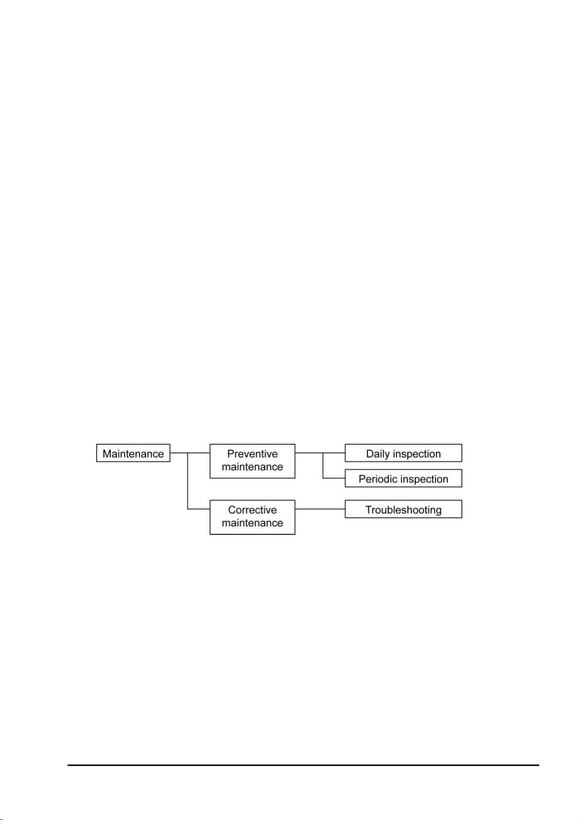
9. MAINTENANCE AND CHECK.............................................................................................................. 46
9.1 Checking ................................................................................................................................................ 46
9.2 Spare parts.............................................................................................................................................. 46
9.3 Replacement of fuse............................................................................................................................... 47
9.4 Adjustment of monitor contrast.............................................................................................................. 48
9.5 Troubleshooting ..................................................................................................................................... 49
10. SETTING AND OPERATING OF PARAMETER............................................................................... 51
10.1 Measured menu.................................................................................................................................... 51
10.1.1 Display range setting screen.......................................................................................................... 51
10.1.2 Decimal point position setting screen............................................................................................ 52
10.1.3 Full scale setting screen................................................................................................................. 53
10.1.4 Setting screen for calculation time of maximum and minimum values appears ........................... 54
10.2 Calibration menu.................................................................................................................................. 55
10.2.1 Automatic calibration setting (option)........................................................................................... 55
10.2.2 Date and time for starting automatic calibration (option) ............................................................. 56
10.2.3 Cycle time setting of automatic calibration (option)..................................................................... 57
10.2.4 Performing all calibration (option)................................................................................................ 58
10.2.5 Performing a manual span calibration........................................................................................... 59
10.2.6 Performing a manual zero calibration ........................................................................................... 60
10.2.7 Calibration gas setting ................................................................................................................... 61
10.2.8 Calibration waiting setting (option)............................................................................................... 62
10.2.9 Calibration error clear ................................................................................................................... 63
10.2.10 Operation setting screen of calibration range.............................................................................. 64
10.3 Blowdown menu (option) .................................................................................................................... 65
10.3.1 Automatic blowdown setting......................................................................................................... 65
10.3.2 Date and time setting of automatic blowdown .............................................................................. 66
10.3.3 Automatic blowdown cycle setting ............................................................................................... 67
10.3.4 Procedure for setting blowdown time............................................................................................ 68
10.3.5 Perfoming manual blowdown........................................................................................................ 69
10.4 Maintenance menu ............................................................................................................................... 70
10.4.1 Error log display............................................................................................................................ 70
10.4.2 Clearing error logs......................................................................................................................... 72
10.4.3 Alarm log display .......................................................................................................................... 73
10.4.4 Clearing alarm logs ....................................................................................................................... 74
10.4.5 Performing a manual sensor check................................................................................................ 75
10.4.6 Maintenance mode setting............................................................................................................ 76
10.4.7 Password setting ............................................................................................................................ 77
10.4.8 PID auto tuning ............................................................................................................................. 78
10.5 Parameter menu ................................................................................................................................... 79
10.5.1 Current date and time setting......................................................................................................... 79
10.5.2 Contact input setting...................................................................................................................... 80
10.5.3 Selection of alarm contact output.................................................................................................. 81
10.5.4 High limit setting of oxygen concentration ................................................................................... 82

- ix -
INZ-TN2ZKMA-E
10.5.5 Lower limit setting of oxygen concentration .................................................................................83
10.5.6 HH limit setting of oxygen concentration......................................................................................84
10.5.7 LL limit setting of oxygen concentration .......................................................................................85
10.5.8 Hysteresis Setting...........................................................................................................................86
10.5.9 Hold treatment setting (maintenance hold) ...................................................................................88
10.5.10 Hold value setting (maintenance hold)........................................................................................89
10.5.11 Setting of hold setting value (maintenance hold) ........................................................................90
10.5.12 Setting of measurement recovery time (maintenance hold)........................................................91
10.5.13 Hold treatment setting (error hold)..............................................................................................92
10.5.14 Hold value setting (error hold).....................................................................................................93
10.5.15 Setting of hold setting value (error hold) ....................................................................................94
10.5.16 Setting of key lock .......................................................................................................................95
10.5.17 Setting of automatic OFF time.....................................................................................................96
10.5.18 Station number setting..................................................................................................................97
10.5.19 Adjustment screen for analog output 0% .....................................................................................98
10.5.20 Adjustment screen for analog output 100% .................................................................................99
10.5.21 Fuel coefficient setting (option) .................................................................................................100
10.6 Factory menu ......................................................................................................................................101
10.6.1 Password setting screen................................................................................................................101
11. SPECIFICATIONS ................................................................................................................................102
11.1 Specifications......................................................................................................................................102
11.2 Code symbols......................................................................................................................................104

- x - INZ-TN2ZKMA-E
CHECKING OF CONTENTS OF THE PACKAGE
Check that all of the following are contained in the delivered package.
(1) Zirconia Oxygen Analyzer Converter main unit 1 unit
(2) Accessories 1 set (Refer to the table below.)
Table 1 Standard accessories
No. Item Q'ty Remarks
1 Fuse 2 250 V T 2.5 A
2 Ferrite core 1 For power cable
3 Instruction manual 1 Japanse, English, or Chinese (depends on the specifica-
tion)
4
Instruction manual (RS485
communication or HART
communication)
1
When you specified RS485 communication or HART
communication.
Language: Japanse, English, or Chinese (as specified)
5 Mounting bracket 1 set
For panel mount version
: M8 sems screw (stainless steel), 4 pcs
For pipe mount version
: U bolt (stainless steel ), 2 pcs
: M8 nut, washer (stainless steel) 4 pcs
: support 2 pcs
STORAGE CONDITIONS
Store the unit in a location that meets the following conditions:
(1) Vibration, dust, dirt, and humidity are minimal.
(2) A place not subjected to radiated heat from a heating furnace, etc.
(3) The atmosphere is non-corrosive.
(4) The ambient temperature is within the range from -30°C through 70°C (no condenstaion) and the
ambient humidity is 95%RH or lower.

- 1 -
INZ-TN2ZKMA-E
1. GENERAL
This manual describes the installation, operation, and the maintenance of the zirconia oxygen analyzer con-
verter. Read it carefully before using the converter. For the detector, flow guide tube and ejector used with
the converter, refer to relevant instruction manuals.
1.1 Direct insertion type zirconia oxygen analyzer
The direct insertion type zirconia oxygen analyzer consists of a direct insertion type zirconia detector (type
ZFK) and converter (type ZKM).
The analyzer intended for the measurement of oxygen concentration in exhaust gas is used for combustion
control.
Caution
Power voltage for the converter must conform to that for the detector to be connected. Don’t use any
power voltage different from the power specifications of the detector. Otherwise it may result in damage
to the detector.
100/120V AC50/60Hz for ZFK8R1
200/240V AC50/60Hz for ZFK8R3
Operating environment
1) Operating temperature: -20 to 55°C
2) Operating humidity: 95%RH or less, non condensing
3) Power voltage: 100 to 120V AC 50/60Hz or 200 to 240V AC 50/60Hz
4) Pollution degree: 2
5) Installation category: II
6) Altitude: up to 2000m

- 2 - INZ-TN2ZKMA-E
2. OPERATING PARTS AND THEIR FUNCTIONS
2.1 Outline Drawing
(1) ZKMA
(2) ZKMB

- 3 -
INZ-TN2ZKMA-E
2.2 Terminal block
2.3 Didplay and operation panel
No. Name Description
① Display unit Displays the concentration value and setting values.
② LED Lights during power supply.
③ ESC key Used to return to the previous screen or exit the setting.
④ Digit key Used to change the setting values.
⑤ Up key
⑥ ENT key Used to determine the setting values or to start calibration or
other operations.
② LED
① Display
③ ESC key ④
Digit key ⑤ Up key ⑥ ENT key

- 4 - INZ-TN2ZKMA-E
2.4 Internal constitution
(1) ZKMA
(2) ZKMB
You can see the CPU board, the I/O board, and the communication board (optional) if you remove the M3
screw and open the inner cover.
No. Name Description
①CPU board The liquid crystal display and the memory circuit are installed.
②I/O board The input/output circuit and the power circuit are installed.
③Communication board RS485 communication board or HART communication board is installed.
④Fuse Protects the CPU board and the I/O board from over-current.
⑤Terminal block Terminals for power cable, detector cable, and input/output cables.
⑥Earth terminal Used as frame gland (FG).
⑦Packing Protects electrical components from water and dust.
④ Fuse
⑥ Earth terminal
⑤ Terminal block
⑦ Packing
M3 screw
⑦ Packing
① CPU board ②I/O board
④ Fuse
⑤ Terminal block
⑥ Earth terminal
③ Communication
board (optional)

- 5 -
INZ-TN2ZKMA-E
3. INSTALLATION
DANGER
This unit is not explosion-proof type. Do not use it in an atmosphere of explosive gases. Otherwise
serious accidents such as explosion or fire may result.
CAUTION
For installation, observe the rule on it given in the instruction manual and select a place where the
weight of converter can be endured. Installation at an unsuited place may cause turnover or fall and
there is a risk of injury.
Before transport, fix the door so that it will not open. Otherwise, the casing may be separated and fall
to cause an injury.
During installation work, care should be taken to keep the unit free from entry of cable chips or other
foreign objects. Otherwise, it may cause fire, failure or malfunction.
3.1 Installation site
Install the converter in a place that satisfies the following conditions.
(1) Space for periodic inspection and wiring work is available.
(2) Vibration, dust, dirt, and humidity are minimal.
(3) A place not subjected to radiated heat from a heating furnace, etc.
(4) The atmosphere is non-corrosive.
(5) Away from electrical devices that may cause noise trouble (such as motor and transformer), and
equipment that may cause electromagnetic or electrostatic induction trouble.
(6) A place where ambient temperature and humidity are -20 to +55°C and 95%RH or less.
Secure at least 100 mm of space between the converter and nearby wall. Also secure a space of opening the
front cover for maintenance.
Secure a cable wiring space under the case.
O
P
E
N
147147
400 or more
Unit: mm
100
or
more
Top view of mounting (ZKMA)
O
P
E
N
240
100
or
more
240
580 or more
Unit: mm
Top view of mounting (ZKMB)

- 6 - INZ-TN2ZKMA-E
3.2 How to install the converter
3.2.1 Mounting on panel (ZKMA)
Unit: mm
Mounting dimensions Installation
72
4-M8
250
No. Name Quantity
1 Converter 1
2 Sems screw (M8×12) 4
Code Standard tightening torque
M8 12.5 [N・m]
3.2.2 Pipe mounting (ZKMA)
Installation
No. Name Quantity
1 Converter 1
2 Hexagon nut (M8) 4
3 Spring washer (M8) 4
4 Plain washer (M8) 4
5 U bolt (M8) 2
6 Support panel 2
Code Standard tightening torque
M8 12.5 [N・m]

- 7 -
INZ-TN2ZKMA-E
3.2.3 Mounting on panel (ZKMB)
Unit: mm
Mounting dimensions Installation
4-M8 72
312
No. Name Quantity
1 Converter 1
2 Sems screw (M8×12) 4
Code Standard tightening torque
M8 12.5 [N・m]
3.2.4 Pipe mounting (ZKMB)
Installation
Pipe for
mounting
5
6
1
2
3,4
52
3,4
No. Name Quantity
1 Converter 1
2 Hexagon nut (M8) 4
3 Spring washer (M8) 4
4 Plain washer (M8) 4
5 U bolt (M8) 2
6 Support panel 2
Code Standard tightening torque
M8 12.5 [N・m]

- 8 - INZ-TN2ZKMA-E
4. WIRING AND PIPING
DANGER
Do not energize the transmitter or equipment connected to the transmitter until all the wiring
work are completed.
CAUTION
This product is compliant with CE marking.
If you need the product to meet the requirements of CE marking, carry out the wiring work ac-
cording to the following instructions:
Add an external switch or a circuit breaker to the power supply of the transmitter.
Use the external switch or the circuit breaker that is rated to 5A and compliant with IEC947-1 or
IEC947-3.
We recommend installing the internal switch or the circuit breaker in the same room as the transmitter
is installed.
Place the internal switch or the circuit breaker within the reach of an operator, and indicate that it is
the power switch of this product.
: Turn off all the power supply during wiring work, otherwise electric shock may occur.
: Be sure to ground the earth (Class D grounding).

- 9 -
INZ-TN2ZKMA-E
4.1 Before wiring
(1) Power voltage for the converter must conform to that for the detector to be connected.
(2) Power supply wiring
Use 1.25sq 600V vinyl insulated cable (JISC3307) or equivalent as power supply cable.
Use the main ground wire longer than the L1 and L2 lines.
Fix the part of the AC cable sheath that is more inner than the cord bushing by 3 mm or more.
Use a solderless terminal for the end of the AC cable. For the main ground wire, use the solderless
terminal whose core wire and sheath are caulked separately (double caulking).
Connect the ground wire to the following:
M4 screw / round terminal of the main ground wire / tooth lock washer / casing
(3) Provide adequate protection of the exclusive cable (6 cores in total), which connects the detector to
converter, using wire protection tube, etc. Separate these cables from the power cable (noise preven-
tion).
(4) Keep the wire for output signals as far as possible (more than 30cm) from the power line and heavy
current lines to prevent induced noise. Also, wherever possible use a shielded cable and earth one
point of the shield.
Note) For connection of the lines to the external terminals, use of ring crimp solderless terminal
with insulation sleeve is recommended.
This manual suits for next models
1
Table of contents
Other Fuji Electric Analytical Instrument manuals
Popular Analytical Instrument manuals by other brands

Trebs
Trebs Comfortcam 22127 manual

Stanley
Stanley STHT1-77366 user manual

Macherey-Nagel
Macherey-Nagel NANOCOLOR 500 D manual

CONDTROL
CONDTROL Sputnik 30 user manual

Uemsi
Uemsi U-VUE Operation and maintenance manual

Bühler technologies
Bühler technologies GAS 222.31 Ex1 Installation and operation instruction