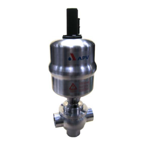
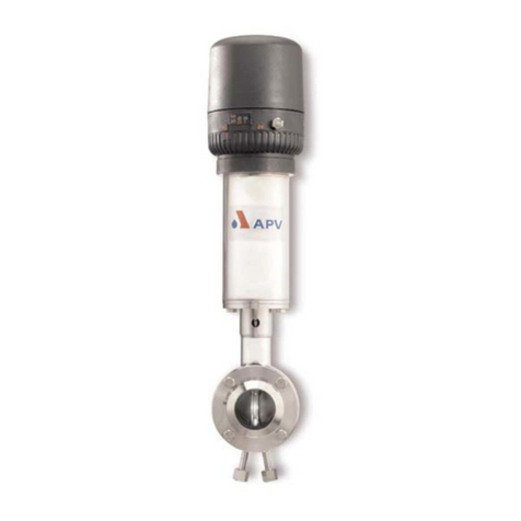
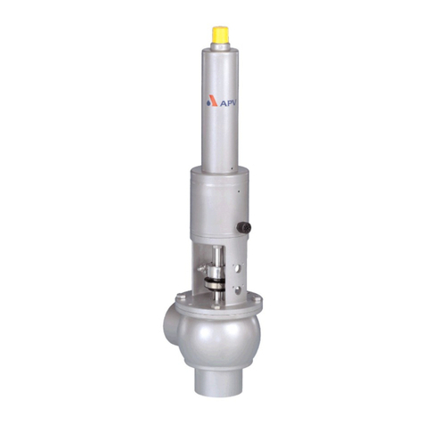
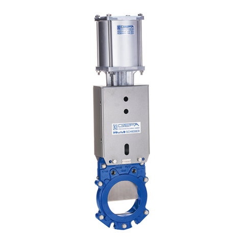
SPX APV DELTA DE3 User manual

Read and understand this manual prior to
operating or servicing this product.
Operating Manual
DELTA DE3
Double eat Mixproof Valve


Content : Page :
1. General Terms 2
2. Safety Instructions 2
3. Mode of Operation 3 - 4
3.1 General Terms
3.2 Valve in "closed" position
3.3 Valve in "open" position
4. Auxiliary Equipment 5
4.1 Valve position indication (proximity switches)
4.2 CONTROL UNIT
5. Cleaning 6 - 7
5.1 Flow areas
5.2 Leakage chamber
5.2.1 Cleaning recommendation
5.2.2 Flushing quantity
5.2.3 Cleaning pressure CIP-connection
5.3 Cleaning of shaft surfaces (option)
5.3.1 Flushing and sterilisation of shaft surfaces
5.3.2 Installation of hose connections
6. Installation 8
6.1 Welding instructions
7. Dimensions / Weights 9
8. Technical Data 10 - 11
8.1 Air consumption / closing times
8.2 Kvs - values
8.3 Valve stroke open / closed
9. Materials 12
10. Maintenance 12
11. Service Instructions 13 - 17
11.1 Dismantling from piping system
11.2 Disassembly of product-wetted seals
11.3 Maintenance of main cylinder
11.3.1 Disassembly of main cylinder and dismantling of seals
11.3.2 Installation of seals and assembly of main cylinder
11.4 Installation of seals and assembly of valve
11.5 Installation of valve insert
12. Disassembly and Assembly Tool 18
(lower shaft seal)
13. Service Instructions - Shaft Flushing 19
14. Service Instructions - Seat Seals 20
15. Detection of seal damage 21
16. Spare Parts Lists and Lubrication Chart
DE 3 DN RN - 01.053.71
DE 3 Inch RN - 01.053.71-2
DE 3 Lubrication chart RN - 260.068-1
DELTA DE3-UK4.qxp / 09.2005
UK
1
Double Seat Valve
DELTA DE 3
Operating Manual : rev. 4


2
This operating manual should be read carefully by the competent
operating and maintenance personnel.
We point out that we will not accept any liability for damage
or malfunctions resulting from the non-compliance with this
operating manual.
Descriptions and data given herein are subject to technical changes.
2. Safety Instructions
Danger
- The technical safety symbol draws your attention to important
directions of operating safety. You will find it wherever the activities
described are bearing risks of personal injury.
-Disconnect electrical and pneumatic connections.
- Depressurize the line and cleaning system and discharge the lines,
if possible, before any maintenance work.
-Observe Service Instructions to ensure safe maintenance
of the valve.
-Connections which are not used must be sealed by a plug.
-A safe discharge of the cleaning liquids must be ensured.
- The valve must only be assembled, disassembled and reassembled
by persons who have been trained in APV valves or by APV service
team members. If necessary, contact your local APV representative.
- Welded actuators are preloaded by spring force.
Opening of the actuators is strictly forbidden.
Danger to life!
Actuators which are no longer used and / or defective
must be disposed in professional manner.
Defective actuators must be returned to your
APV Solutions & Services company
for their professional disposal and
free of charge for you.
Please address to your local APV representative.
1. General Terms
!
!
UK
DELTA DE3-UK4.qxp / 09.2005
Double Seat Valve
DELTA DE 3
Operating Manual : rev. 4

3Double Seat Valve
DELTA DE 3
Operating Manual : rev. 4
3. Mode of Operation
3.1 General Terms
Due to its construction and mode of operation as well as to
the use of high quality stainless steel and adequate seal materials,
the double-seat mixproof valve DELTA DE3 is suited for applications
in the food and beverage industries as well as in the pharmaceutical
and chemical industries.
- The valve opens from the top to the bottom in low leakage operation
(unpressurized drain of fluid residues via the annular cleaning gaps
in the seat area).
-Separation of two line passages by two balanced and
independently operating valve slides with intervening leakage
chamber. Flushing connection at (B1).
- Double sealing function by two seals acting independently of
one another.
-Arising leakages at the seat seals are discharged at (C) in
depressurized state.
- Proximity switches can be installed as valve position indicators.
(Fig. 3.1)
D1 = valve position "closed"
D2 = valve position "open" (only with DN 40 - 50 , 1,5" - 2")
D3 = valve position "open" (only with DN 65 to 150, 2,5" - 6")
-Operation by pneumatic actuator with air connection at (A). Reset
by spring force into the safety limit position "closed".
-Maintenance-free actuator.
-Optical indication of the valve position at the actuator.
D1
D2
D3
B1
C
A
optical indication of
valve position
fig. 3.1
main cylinder
Federzylinder
housing
UK
DELTA DE3-UK4.qxp / 09.2005

4
Double Seat Valve
DELTA DE 3
Operating Manual : rev. 4
3.2 Valve in "closed" position (fig 3.2)
The lower and upper valve shafts are closed by spring force
and safely separate the different fluids Aand B. The leakage
chamber Lwhich is situated between the two valve shafts,
provides for a free and absolutely depressurized discharge to
the bottom. The valve shafts are balanced and, thus, safe against
pressure hammers.
3.3 Valve in "open" position (fig 3.3)
During the opening process, the leakage chamber Lis closed
against the product area and the pipelines Aand Bare connected.
In open valve position, the valve shafts are also balanced and,
thus, safe against pressure hammers.
3. Mode of Operation
fig. 3.3
fig. 3.2
UK
DELTA DE3-UK4.qxp / 09.2005

5Double Seat Valve
DELTA DE 3
Operating Manual : rev. 4
4.1 Valve position indication
Proximity switches to signal the limit position of the valve shafts
can be installed at the actuator if requested (fig. 4.1).
We recommend to use our APV standard types:
operating distance: 5 mm / diameter: 11 mm
If the customer decides to use valve position indicators other than
APV type, we cannot take over any liability for a faultless function.
4.2 Control Unit
The installation of a CU3 control unit on a DE3 valve is possible.
Start-up, assembly and dismantling of the different designs are
described in the corresponding operating manual.
The following different designs are available:
4. Auxiliary Equipment
- For the installation of the control unit on the DE3 valve an adapter
is required.
1 soleniod valve (EMV)
CU31 DE3 Direct Connect
16-31-234/93
CU31 - DE3 Profibus
08-45-003/93
CU31 DE3 Device Net
16-31-242/93
CU31 DE3 ASInterface 2.1
08-45-022/93
Direct Connect
ref.-No.:
Profibus
ref.-No.:
Device Net
ref.-No.:
ASInterface
ref.-No.:
1 soleniod valve (EMV)
CU21 - adapter DA3 / DE3
08-48-424/93
designation:
ref.-No.:
4.2 Control Unit
fig. 4.1
DE3 - CU
UK
position of
proximity
switches
closed
position
open position
for DN 40, 1,5”
open position
for DN 50-150, 2”-4”
DELTA DE3-UK4.qxp / 09.2005

6
Double Seat Valve
DELTA DE 3
Operating Manual : rev. 4
5. Cleaning
With the cleaning of DELTA DE3 valves, one has to distinguish
between three areas:
5.1 The flow areas
The upper and lower passages are cleaned by the passing
cleaning liquid during the cleaning of the connected pipelines.
5.2 The lekage chamber (fig. 5.2)
The cleaning of the leakage chamber is undertaken by CIP
spraying. CIP cleaning connection (B1).
!CIP must generally be undertaken.
The spraying does not produce pressure build-up in the
leakage chamber and can be carried out in closed and in open
valve position.
The conduct of the cleaning liquid provides for a perfect cleaning
of the whole leakage chamber.
Under normal conditions
15 valves DN 40 - 100, 1,5" - 4"
10 valves DN 125 - 150, 6” can be cleaned
via one spray distribution line DN 25.
5.2.1 Cleaning recommendation for interval and spraying liquid
under normal operating conditions and with common
CIP liquids.
-Depending on the pressure ratio, cleaning temperatures and the
degree of soiling, different cycles must be adjusted.
5.2.2 Flushing quantities
per CIP cycle: DN 40 - 100, 1,5” - 4” ca. 1,2ltr/10s
per CIP cycle: DN 125 - 150, 6” ca. 5ltr/10s
5.2.3 Cleaning pressure at CIP cleaning connection: min. 2 bar.
max. 5 bar.
cleaning step
pre-flushing
caustic flushing 80 oC
intermediate flushing
acid flushing
subsequent flushing
CIP spraying
3 x10 sec.
3 x10 sec.
2 x10 sec.
3 x10 sec.
2 x10 sec.
fig. 5.2
DELTA DE3-UK4.qxp / 09.2005
UK

7Double Seat Valve
DELTA DE 3
Operating Manual : rev. 4
UK
5. Cleaning
5.3 Shaft surfaces outside the flow passages (option)
The DE3 valve provides for those areas of the upper and lower
shaft stem which are not subject to cleaning, to be flushed (fig. 5.3).
Shaft flushing is recommended with sensible products to
increase product safety and the service life of seals.
The connection of the flushing device is done according to the
pattern described on the left via push-in flushing connections.
Assembly instruction for shaft flushing: see chapter 13.
5.3.1 Flushing and sterilisation of shaft surfaces
The following flushing liquids are permissible:
- hot water
(slightly sour to avoid lime residues) : max. 85oC
- common CIP liquids : max. 80oC
-supply pressure at CIP cleaning
connection : min. 1 bar.
max. 3 bar.
- flushing quantity per CIP cycle : ca. 1,2 ltr./10s
cleaning period : 30s
-interval : 1x / day (e.g. with milk)
- depending on product and
operating frequency : 1x / week (e.g. with beer)
-Under normal conditions
15 valves DN 40 - 100, 1,5” - 4”
10 valves DN 125 - 150, 6”
can be cleaned via one spray distribution line DN 25.
The free discharge of cleaning liquids and steam must
be ensured.
The upper and lower shaft flushing may only be carried
out if product is not imminent in the appertaining part of the
housing.
5.3.2 Installation of the hose for cleaning liquids:
B4 OUT
B2 IN
B3 IN
C
lower
shaft flushing
cleaning liquid supply B2
cleaning liquid discharge C
Identification on
spring cylinder
at drain pipe
fig. 5.3
!
DELTA DE3-UK4.qxp / 09.2005
upper
shaft flushing
cleaning liquid supply B3
cleaning liquid discharge B4
in
out

8
Double Seat Valve
DELTA DE 3
Operating Manual : rev. 4
6. Installation
- The valve must be installed in vertical position. Fluids are,
therefore, freely drainable from the valve housing and the
leakage chamber.
- Valve housings can be welded direct into the pipelines (completely
dismantable valve insert).
-Attention: Observe welding instructions.
- Heights of installation and dismantling (see chapter 7).
6.1 Welding Instructions
DE3
- Before welding of the valve, the valve insert must be dismantled
from the housing. Careful handling to avoid damage to the parts
is necessary (see 11.1). It is not necessary to remove the lower
shaft seal as it can be destroyed during dismantling.
- Welding should only be carried out by certified welders (EN 287-1).
(Seam quality EN 25817 "B").
- The welding of the valve housings must be undertaken in such a
way that the valve body is not deformed.
- The preparation of the weld seam up to 3 mm thickness shall be
carried out as a square butt joint without air. (Consider shrinkage!)
- TIG orbital welding is best!
-After welding of the valve housing or of the mating flanges and
after work at the pipelines, the corresponding parts of the
installation and pipelines must be cleaned from welding residues
and soiling before operation of the valves to avoid damage
to the valves and seals.
If these cleaning instructions are not observed, welding residues
and dirt particles can settle in the valve and cause damage.
-Any damage resulting from the non-observance of these welding
instructions is not subject to our guarantee.
UK
DELTA DE3-UK4.qxp / 09.2005

9Double Seat Valve
DELTA DE 3
Operating Manual : rev. 4
7. Dimensions / Weights
L1
A1
B
Y X
H
Di
A
F F
G
L
125
dimensions in mm weight
in kg
Control Unit
DELTA CU3
DELTA DE3-UK4.qxp / 09.2005
UK
DN
34,9
47,6
60,3
72,9
97,6
146,9
429
435
439
445
475
705
118
125
131
137
155
188
305
311
315
321
351
481
100
100
100
100
120
150
163
163
163
163
188
264
63
75
91
106
125
175
611
635
655
679
755
1068
FL
163
163
163
188
188
230
264
487
511
543
593
631
745
844
10,1
10,2
10,4
14,6
15,5
30,8
----
10,1
10,2
10,4
10,5
15,5
---
inch
40
50
65
80
100
125
150
120
126
134
146
156
176
189
L1 X
552
572
592
673
703
740
971
200
218
242
274
303
342
392
552
572
592
622
703
971
197
216
233
251
301
391
Y
487
511
531
555
631
844
611
635
667
717
755
869
1068
AB
428
434
442
464
474
544
704
304
310
318
340
350
420
480
A1
38
50
66
81
100
125
150
Ø Di
1,5”
2”
2,5”
3”
4”
6”
Ø G
100
100
100
120
120
150
150
H
63
75
91
106
125
150
175
installation
dimensions
min. in mm

10
Double Seat Valve
DELTA DE 3
Operating Manual : rev. 4
8. Technical Data
max. line pressure : 10 bar
max. operating temperature : 135°C EPDM, HNBR
short - term temperature : 140°C EPDM, HNBR
tightening torque of stop screw
at lower valve shaft :25Nm
tightening torque of safety nut
at upper and lower valve shaft :40Nm
leakage gap between
upper and lower valve shaft : ca. 4mm
fig. 8
(check after stop screw being screwed in)
cleaning connection (for hose)
DN 40 - 100, 1,5” - 4” :8x1mm
DN 125 - 150, 6” : 10x1mm
air connection (for hose) :6x1mm
max. pneumatic air pressure : 10 bar
min. pneumatic air pressure : 6 bar
(Use dry and clean air only)
upper shaft
fig.8
lower shaft
leakage gap
about 4mm
UK
air consumption
actuator in
NL / stroke
closing times
in sec.
hose length
DN / inch
40 / 1,5”
50 / 2”
65 / 2,5”
3”
80
100 / 4”
125
150 / 6”
1m
1,5
1,5
1,5
1,5
3,0
3,0
5,0
8,0
10m
2,5
2,5
2,5
2,3
4,0
4,0
6,0
9,0
0,9
1,1
1,3
1,3
2,3
2,3
4,0
6,4
8.1
DELTA DE3-UK4.qxp / 09.2005

11 Double Seat Valve
DELTA DE 3
Operating Manual : rev. 4
8. Technical Data
* no measuring value
fig. 8.3
8.2 kvs - values in m 3/ h
H2
B
A
C
H1
valve position
closed
valve position
open
upper
valve shaft
lower
valve shaft
8.3 table to fig. 8.3
dimensions in mm
DN
inch
stroke H2
lower shaft
BA
40
50
65
80
100
125
150
6,5
11,5
21,5
31,5
50,5
69,5
86,5
6,5
11,5
15,5
27,6
50,5
86,5
5
12
18
18
23
37
5
12
18
23
23
29
37
C
21,2
21,2
21,2
21,2
36,2
54,7
21,2
21,2
21,2
36,2
36,2
42,7
54,7
stroke H1
upper shaft
26
33
39
44
44
50
58
30
37
43
48
48
54
62
26
33
39
39
44
58
30
37
43
43
48
62
1,5”
2”
2,5”
3”
4”
6”
DELTA DE3-UK4.qxp / 09.2005
UK
DN
40 57 46 23 25
50 120 95 42 45
65 219 148 69 78
80 296 200 120 130
100 505 320 164 170
125 800* 500* 300 330
150 1200* 700* 360 380
inch
1,5” 47 40 21 24
2” 100 73 43 46
2,5” 170 122 59 66
3” 213 160 71 80
4” 490 294 150 160
6” 1150* 670* 340 360

Double Seat Valve
DELTA DE 3
Operating Manual : rev. 4
12
9. Materials
product-wetted parts 1.4571, 1.4404
other parts 1.4301
seals:
standard EPDM/PTFE
option HNBR/PTFE
actuator PA 12 GF 30
shaft bearing PPS
spray connection PP GF30
10. Maintenance
- The maintenance intervals depend on the application and should
be determined by the user carrying out regular checks.
-Compressed air is not required to dismantle the valve.
- Tools required:
-1 x spanner SW13
-2 x spanner SW17
-2 x spanner SW24
-disassembly and assembly support for the lower shaft seal
ref.-No. 000 51-13-100/17
- Replacement of seals according to Service Instructions.
The customer is recommended to hold spare seals on stock.
For valve maintenance APV supplies complete seal kits including
seal grease (pl. see spare parts lists).
- The valve must not be cleaned with products containing abrasive
or polishing substances. Especially the valve shafts must not be
cleaned with such agents under any circumstances. Damage of
the valve shaft can produce leakages.
-Assembly of the valve according to Service Instructions.
-All seals must be provided with a thin layer of grease before
their installation. (see lubrication chart)
Recommendation:
APV food-grade-grease for EPDM, HNBR and FPM
(0,75 kg /tin - ref.-No. 000-70-01-019/93)
(60 g /tube - ref.-No. 000-70-01-018/93)
! Do not use grease on mineral oil basis for EPDM seals.
Recommendation for the actuator:
APV pneumatic grease
(25 ml /tube) - ref.-No. 000-70-01-008/93)
UK
DELTA DE3-UK4.qxp / 09.2005

13 Double Seat Valve
DELTA DE 3
Operating Manual : rev. 4
The item numbers refer to the spare parts drawings
DIN design: RN 01.053.71
Inch design: RN 01.053.71-2
11.1 Dismantling from the piping system
a. Shut off the line pressure in the product and cleaning lines,
discharge the pipes if possible.
b. Remove the pneumatic air line and the flushing connection lines.
c. Release the nut of the proximity switch holder (35) and pull off the
proximity switch.
- With CU design: Take off the control unit by turning the
safety ring.
d. Remove the hex. screws (7) at the spring cylinder (8).
e. Screw in one flange screw into the threaded bore of the spring
cylinder to lift the complete valve insert. Do not remove the screw
which will help to re-install the valve insert.
f. Carefully lift the valve insert vertically out of the valve housing.
11. Service Instructions
valve housing
valve insert
7
8
!
DELTA DE3-UK4.qxp / 09.2005
UK
35

14
Double Seat Valve
DELTA DE 3
Operating Manual : rev. 4
11.2 Dismantling of product-wetted parts (service)
-With CU design: Release the 4 inner hex. screws and take
off the CU adapter.
a. Screw off the stop screw (11).
b. Release the lower safety nut (31). Hold up the lower shaft (3) with
a spanner SW17 to prevent it from turning.
c. Having removed the nut (31), pull the lower shaft (3) off the
guide rod (4).
d. Dismantling of seals from the lower shaft (3). Stick into the lower
seat seal (28) with a peaked object and pull the seal out of the
groove. Pull the o-ring (29) out of the groove.
e. Pull off the guide rod to the top.
f. Remove the safety nut (12). Holding up the safety disc (13) with
a spanner SW24 prevents the upper shaft (5) from turning.
g. Lift off the main cylinder (10) with spring cylinder (8) and shaft
bearing (23) (maintenance of spring cylinder, see 11.3).
h. Dismantling of seals from the upper shaft (5). Stick into the upper
and middle seat seal with a peaked object und pull them out of
the groove. Afterwards, lift the two supporting rings (26) and the
quadring (27) off the groove.
i. Dismantling of seals from the shaft bearing (23). Remove the upper
shaft seal (24, 25) from the groove. Take the quadring (22) and
o-ring (37) out of the groove.
j. Dismantling of lower shaft seal (24, 25) from the housing.
Take the metallic tip of the dismantling tool to stick into the
elastomer seal (25) from the top and pull the seal off to the top.
Then, take the tip of the assembly tool to pull the PTFE seal (24)
off to the top through the housing.
11. Service Instructions
UK
DELTA DE3-UK4.qxp / 09.2005
11
12
13
14
22
8
10
23
37
31
3
28
28
26, 27
24, 25
29
4
5

15
UK
Double Seat Valve
DELTA DE 3
Operating Manual : rev. 4
11.3 Maintenance of main cylinder
Dismantle the actuator, main cylinder (10) and
spring cylinder (8) from the valve insert as described
in 11.2 a.-g.
11.3.1 Disassembly of main cylinder and dismantling of seals
a. Remove the fastening screws (14).
- Remove the main cylinder (10) from the spring cylinder.
b. Press the piston rod out of the main cylinder.
Remove the cover and the piston with piston rod.
c. Draw the piston rod out of the piston.
d. Remove the quadring in the piston and in the main cylinder.
e. Remove the piston seal.
f. Clean the main cylinder, cover, piston rod and piston.
11.3.2 Installation of seals and assembly of main cylinder
a. Slightly grease the quadrings and the piston seal.
Use appropriate pneumatic grease.
-Recommendation for actuator (main cylinder):
APV pneumatic grease:
(25 ml tube - ref.-No. 000 70-01-008/93)
b. Insert the quadrings and the piston seal.
c. Assembly to be undertaken in reverse order to the procedure
described in 11.3.1.
11. Service Instructions
piston
cover
quadring
quadring
piston rod
signalring
signal ring
piston seal
main cylinder
DELTA DE3-UK4.qxp / 09.2005
Table of contents
Other SPX Control Unit manuals

SPX
SPX 9500 Product guide
SPX
SPX APV DELTA DF plus 2 User manual
SPX
SPX APV DELTA SDU4 User manual
SPX
SPX APV DELTA PR2 User manual

SPX
SPX Waukesha Cherry-Burrell W-Series User manual
SPX
SPX APV DELTA DET3 User manual
SPX
SPX APV CU4 User manual

SPX
SPX Waukesha Cherry-Burrell W Series User manual
SPX
SPX DELTA SW4 User manual
SPX
SPX W Series User manual
