SPX RADIODETECTION 1205CXB User manual
1205CXB™
Time Domain Reectometer
and Cable Analyser
User Guide
90/1205CXB-UG-ENG/02


3
Preface
Thank you for your interest in Radiodetection’s 1205CXB™cable fault locator.
Please read this User Guide in its entirety before attempting to use the
1205CXB.
Radiodetection products and documents, including this User Guide, are under
continuous development. The information contained within is accurate at time
of publication; however the 1205CXB, this user guide and all its contents are
subject to change.
Radiodetection Limited reserves the right to modify the product without notice
and some product changes may have taken place after this user manual was
published.
Contact your local Radiodetection dealer or visit www.radiodetection.com for
the latest information about the 1205CXB product family, including this guide.
CAUTION: This guide provides basic operating instructions for the
1205CXB TDR and cable fault locator. It also contains important safety
information and guidelines and as such should be read in its entirety
before attempting to operate the 1205CXB.
This guide is intended as a quick reference guide only. For detailed instructions,
including the use of accessories, refer to the 1205CXB Operation Manual,
which is available for download from www.radiodetection.com.
Certicates of conformity are also available from www.radiodetection.com.
4
Warnings
Before using, review all safety precautions. Note and observe all warning and
caution statements on the equipment and in the documentation.
The 1205CXB contains no user serviceable parts. Do not modify any part or
accessory of this instrument. If the unit is damaged, do not use. Also, secure
the product from use by others.
WARNING! Direct connection to live cables is POTENTIALLY LETHAL.
WARNING! To avoid electric shock, do not remove covers or any parts
of the enclosure.
WARNING! The 1205CXB contains a Lithium-Ion battery. Do not
exceed the maximum rated charging current of 2A.
WARNING! The 1205CXB is not intrinsically safe or Ex rated, do not
operate it near ammable gases or fumes.
If the instrument or any associated accessory is used in any manner not
detailed by the accompanying documentation, the safety of the operator may
be compromised.
Do not expose the equipment to extreme temperatures. Store the instrument
indoors during extreme hot or cold temperatures and bring the instrument to
within specied operating temperatures (0 to +50°C/32 to 122°F) before using.
FCC Statement: This equipment has been tested and found to comply
with the limits for a Class A digital device, pursuant to part 15 of the
FCC Rules. These limits are designed to provide reasonable protection
against harmful interference when the equipment is operated in a
commercial environment. This equipment generates, uses, and can radiate
radio frequency energy and, if not installed and used in accordance
with the instruction manual, may cause harmful interference to radio
communications. Operation of this equipment in a residential area is likely
to cause harmful interference in which case the user will be required to
correct the interference at his own expense.
Canada: CAN ICES-003(A) / NMB-003(A)

5
Description
The 1205CXB is a Time Domain Reectometer, also known as a Cable Radar.
Electrical pulses are transmitted into a cable, and a portion of the pulse energy
is reected back from cable imperfections. These can be discontinuities
(eg cable joints, changes in cable type or the far end of the cable under test)
or faults (typically short circuits, open circuits, high resistance joints or water
ingress).
The transmitted pulse and the reected pulse(s) are shown on the display.
The time taken by the pulse to travel to the imperfection and back is a measure
of the distance to the fault. The distance is displayed after the cursor is
positioned at the start of the reected pulse. The type of imperfection can be
assessed by analysing the displayed waveform.
NOTE: The cable must contain at least two conductors or one conductor and
screen. This can be generalized to include other multi-conductor set ups such
as district heating systems.
Velocity of Propagation (VOP)
The properties of the cable, mainly the insulation between the two conductors,
greatly aect the velocity of the TDR pulses. This velocity is called the Velocity
of Propagation (VOP), or Velocity Factor (PVF). The TDR uses this value to
calculate distance, so it is important for this to be as accurate as possible.
The 1205CXB can accept user selectable values between 10.0% and 99.9%.
The “Operation” section shows how you change the VOP to the desired value.
Before you begin
This guide is intended to be a quick reference guide. We recommend you read
the full Operation Manual before you attempt to operate the 1205CXB.
The 1205CXB contains a Lithium-Ion battery. Charge it using the USB cable
and multi-region charger provided and do not exceed the specied maximum
charging current.

6
1
5
User interface
2
3
4
6 7
89 10 11 12
13
Features
1 USB port
2 BNC cable connector
3 Display
Name Function
4Power Turn 1205CXB On and O
5ConFiGuration Select parameters and auto search in the ConFiG
submenu
6CURsor Select cursor 1 or 2
7WAVEform Select move or zoom function for a waveform
8MENU Select units, a pre-loaded cable and system settings
9SAVE Save waveform to 1205CXB’s memory or USB
10 LOAD Load a waveform from 1205CXB’s memory or USB
11 Left, up, down, right
arrows
Increase/decrease parameters
Zoom, move waveforms and cursors
12 ENTER Conrm menu item or waveform selection
13 ESCape Escape, back one step in the menu
Keypad
7
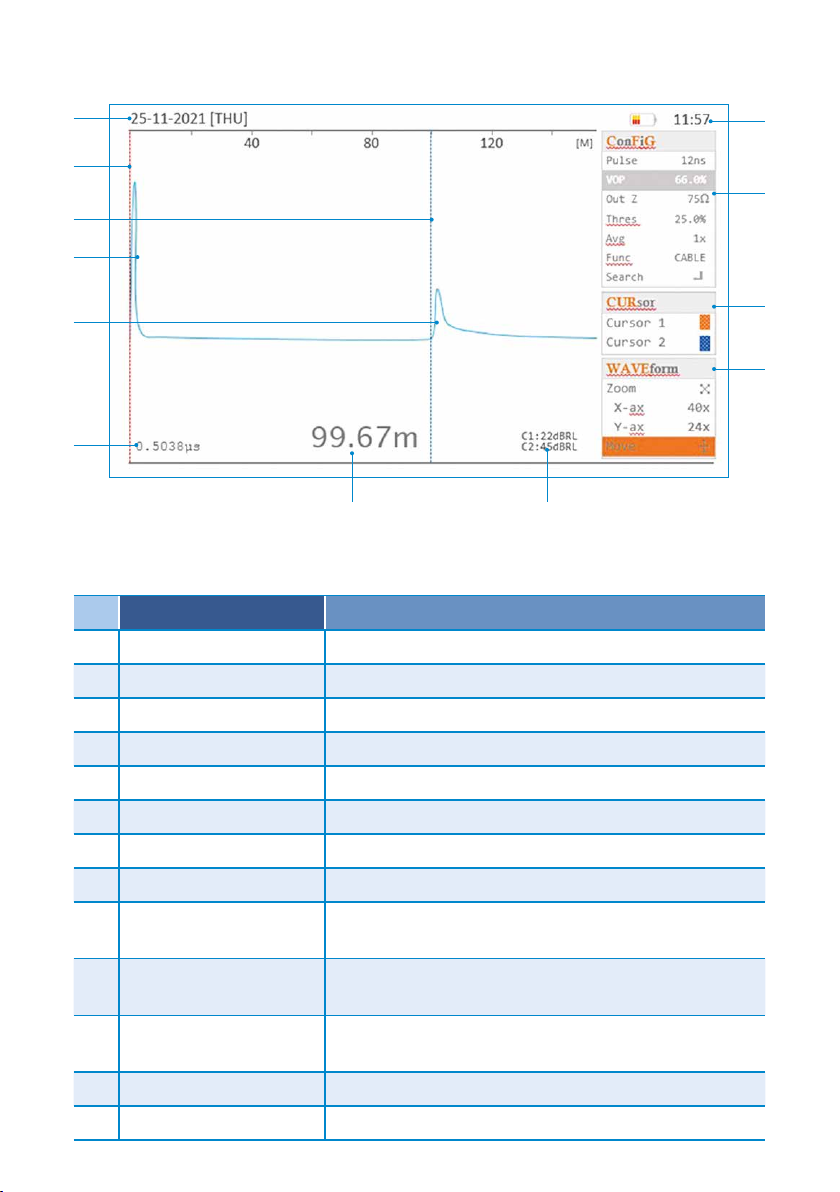
Display features
14
15
25
16
20 21
24
Name Information and use
14 Date Provides date information to stored les
15 Cursor 1 Position for accurate measurement to discontinuities
16 Cursor 2 Position for accurate measurement to discontinuities
17 Launch pulse The pulse sent out by the TDR
18 Reected pulse(s) Pulse(s) reected by a cable discontinuity
19 Time measurement Time for the pulse to reach the discontinuity
20 Distance measurement Distance along the cable to the discontinuity
21 dBRL measurements dB of Return Loss at cursor 1 and 2
22 WAVEform submenu Use, with the arrow keys, to Zoom and Move
waveforms
23 CURsor submenu Select cursor 1 or 2. Move cursors with left and right
arrow keys
24 ConFiGuration
submenu
Change selected parameter with arrow keys
25 Time Provides time information to stored les
26 Battery status Shows battery charge
17
18
19
23
22

8
Operation
1. Press the Power button, 4, to turn 1205CXB on.
2. Connect a cable to the BNC connector, 2.
3. Press the CFG button, 5, repeatedly until VOP is highlighted in the
ConFiGsubmenu, 24.
4. Use the arrow buttons, 11, to set the VOP% to match the VOP% of the
cable. This can usually be found in the cable’s datasheet under VOP,
Velocity of Propagation or Dielectric.
5. Press the CUR button, 6, to highlight Cursor 1, 15, and if necessary, use
the left and right arrow buttons to position Cursor 1 at the start of the
launch pulse, 17.
6. Press the CUR button again to highlight Cursor 2, 16, and use the left and
right arrow buttons to position Cursor 2 at the start of the reected pulse,
18, as shown in the Display diagram.
7. Read the distance, 20, or time, 19, to the discontinuity.
8. Additional functions, such as changing measurement units, setting
date/time, loading a cable from memory, and saving and recalling
waveforms, can be accessed via the MENU button, 8. For details, please
refer to the 1205CXB Operation Manual.
9. Press the Power button, 4, to turn 1205CXB o.
Waveforms
The display of the 1205CXB shows a launch pulse at the left hand side of the
display and a reected pulse if any cable imperfections are within range.
Move Cursor 2 so that it is positioned at the start of the reected pulse,
as shown in the Display diagram. The distance to the imperfection is
then displayed at the bottom of the display. You can change the units of
measurement in the MENU.
Open circuit and high impedance series faults will result in a positive (upward)
reected pulse. Short circuit and low impedance shunt faults will give a
negative (downward) reection.
WaveView™PC software
Radiodetection’s WaveView PC program is a software package that allows you
to view, manipulate, print and archive cable signature waveforms produced by
1205CXB cable fault locator. Visit www.radiodetection.com for a download
link and usage information.

9
Training
Radiodetection provides training services for most Radiodetection products.
Our instructors will train equipment operators or other personnel at your
preferred location or at Radiodetection headquarters. For more information
go to www.radiodetection.com or contact your local Radiodetection
representative.
Software upgrades
From time to time, Radiodetection may release software upgrades to enhance
features and improve performance of the 1205CXB. Software upgrades are
free of charge and provided through a Radiodetection portal, via a computer
running Radiodetection’s WaveView™software.
Care and maintenance
Radiodetection recommends that you service the 1205CXB annually.
The 1205CXB cable fault locator is robust, durable and has a weatherproof
rating of IP54 (lid open) and IP68 (lid closed). However, you can extend your
equipment’s life by following these care and maintenance guidelines:
●Store the equipment in a clean and dry environment
●Ensure connection sockets are clean, free of debris and corrosion and are
undamaged
●Do not use this equipment when damaged or faulty
●Only use a battery charger approved by Radiodetection. Do not exceed the
specied maximum charging current of 2A.
Copyright ©2022 Radiodetection Ltd. All rights reserved. Radiodetection is a subsidiary of SPX Corporation. Radiodetection and
1205CXB are either trademarks of Radiodetection in the United States and/or other countries. Due to a policy of continued development,
we reserve the right to alter or amend any published specication without notice. This document may
not be copied, reproduced, transmitted, modied or used, in whole or in part, without the prior written
consent of Radiodetection Ltd.
For a list of the importers of the 1205CXB into Europe, please visit:
https://www.radiodetection.com/en/european-importers

90/1205CXB-UG-ENG/02
Copyright © 2022 Radiodetection Ltd. All rights reserved. Radiodetection is a subsidiary of SPX Corporation.
Radiodetection and 1205CXB are either trademarks of Radiodetection in the United States and / or other
countries. Due to a policy of continued development, we reserve the right to alter or amend any published
specication without notice. This document may not be copied, reproduced, transmitted, modied or used,
in whole or in part, without the prior written consent of Radiodetection Ltd.
Visit: www.radiodetection.com
Follow us on:
USA
Raymond, ME
Kearneysville, WV
Canada
Vaughan, ON
Mississauga, ON
Europe
United Kingdom HQ
France
Germany
The Netherlands
Asia Pacic
India
China
Hong Kong
Indonesia
Australia
Our Mission
Provide best in class equipment and solutions, to prevent damage
to critical infrastructure, manage assets and protect lives.
Our Vision
To be the world’s leader in the management of critical infrastructure and utilities.
Our locations
Scan to see a
full list of our
oce locations
Table of contents
Other SPX Measuring Instrument manuals


