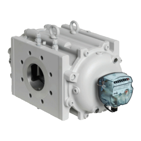
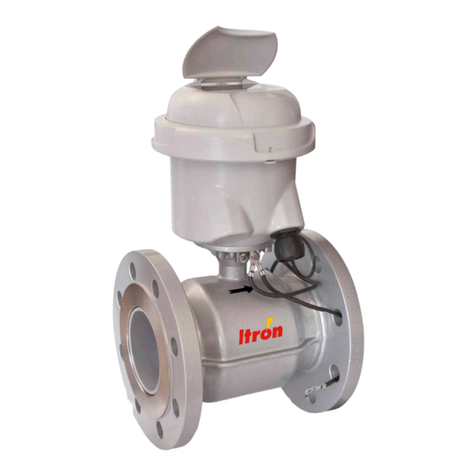
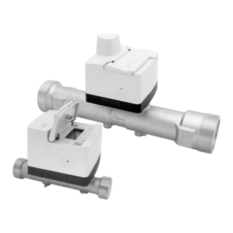
ITRON Axonic User manual

EN
DE
FR
PL
IT
CZ
SLO
RU
CN
User guide................................................................................................... 2
Montage- und Bedienungsanleitung.......................................................10
Manuel d’utilisation ...................................................................................18
Instrukcja obsługi.......................................................................................26
Manuale utente ........................................................................................ 34
Návod k obsluze ........................................................................................42
Navodila za montažo in uporabo............................................................ 50
РУКОВОДСТВО ПО ЭКСПЛУАТАЦИИ ...................................................... 58
安装操作说明........................................................................................... 66
Axonic
USER GUIDE

2
Axonic
User guide
EN
1 - DELIVERY AXONIC
• Check completeness before installation
• 1 flow meter incl. connecting cable (l = 3 m or 10 m)
• Moving flanges. (PN16 and PN25 versions only)
• 1 set of gaskets
• 1 mounting and operation instructions
• Calibration Report and CE-Declaration (depending on country)
2 - GENERAL INDICATIONS
Flow meter AXONIC is a sophisticated electronic measuring instrument for measurement of thermal energy in either hori-
zontal or vertical position. Axonic can be connected to any calculator with compatible signal-input. The following instructions
must be carefully observed in order to ensure correct mounting and to fulfill all safety and guarantee conditions.
2.1 - Advise concerning safety
Hot water circuits and mains power supplies run under high temperatures and pressure as well as under high voltages.
When operated incorrectly, these may cause serious injuries. Due to this, measuring units may only be installed by qualified
and trained personnel. Prior to any installation / de-installation of Axonic it is mandatory to close and empty the concerned
network section. The casings of the heat meters are designed for cold, warm and hot water, with the characteristic values
specified for each case, excluding any other liquid. If the flow meter casing is submitted to strong shocks, impacts, drops
from more than 60 cm height or similar stresses, the heat meter must be replaced. Pipes must be earthed.
The complete system or global installation which will use this equipment must be protected by valve or a pressure limiting
system in order to respect the maximal pressure of the equipment.
2.2 - CE marks and protective classes
Metering unit AXONIC fulfills all requirements of applicable EC guidelines, and is approved in environmental class C (Indus-
trial applications), according to DIN EN 1434, MID environmental class E2 and M2 (MID 2014/32/EU):
• Ambient temperature: -25°C ... +60°C (indoors installation)
• Storage temperature:
- Permanent: T°MIN = -25°C T°MAX = 60°C
- Max +70°C (< 24 hours continuous)
• Flow sensor IP 68 (7 days under 1.2 meter of water at ambient)
• Axonic is conform to DIRECTIVE 2014/68/EU (Heat version only), fluid group 2 (Approved for water only).
• Discarded electronic devices contained within must not be put in normal house hold waste. Dispose in accordance to local
government regulations.
• The metrological class of a complete thermal energy meter, made of subassemblies (flow meter, calculator and temperature
sensors pair), assembled and installed according to the manufacturers installations instructions, meets the metrological class
that is indicated on the flow meter type plate.
• Cooling meter versions meet the requirements of MessEV.
2.3 - Further important indications
• The flow meter must never be lifted or carried by its connecting cable.
• Mounting position shall be selected so that the connecting cable of the flow meter and the temperature probe cables will not
be near mains cables or other sources of electromagnetic disturbances (minimum distance 50 cm).
• Cables must not be installed along pipes reaching temperatures above 60 °C.
• Opening of calibration seals will cause the loss of calibration validation and of guarantee.
• Unsealing the device is excluding the guarantee of conformity to directive PED 2014/68/EU. (Heat version only)
• The casing may only be cleaned on the outside, with a soft, damp cloth. Do not use detergents.
• Installation must be carried out according to EN 1434.
• There may be local rules that must be followed but not covered with this manual. Please check with the experts of the country
in which the meter will be installed.
• In Bi-Functional applications, the durability of the flow sensor is limited to 5 years.
DN65 - PN16,
DN80 - PN16/25,
DN100 - PN16 :
x4

3
Temperature Sensor
Temperature Sensor
Calculator
Flow Sensor
Supply
Return
3 - MOUNTING THE FLOW METER
3.1 - Operating conditions, materials and dimensions
The operating parameters of the heating or cooling circuit must not exceed, Maximal pressure (PMA), Operating tempera-
ture indicated on type plate.
• Max permanent operating temperature: version for heat 130°C/150°C (permanent/accidental); version for cooling 50°C
• PMA at extreme temperatures:
- PN16 120°C < Maximal pressure: 15.2 bar < 130°C
- PN25 120°C < Maximal pressure: 23.8 bar < 130°C
Minimum pressure to ovoid internal cavitation:
• DN65-100
- For fluid temperature < 90°C: minimum pressure = 1 bar
- For fluid temperature ≥ 90°C: minimum pressure = (minimum pressure to keep water at liquid state) + 1 bar
• DN150
- For fluid temperature < 90°C: minimum pressure = 2bar
- For fluid temperature ≥ 90°C: minimum pressure = (minimum pressure to keep water at liquid state) + 1,5 bar
Raw materials in contact with water:
• O-Ring: EPDM (channel) & FKM
• Bodies: Bronze (PN16 and 25), stainless steel (PN40).
• Transducer support: brass plated (PN16 and 25), Stainless steel (PN40)
• Measurment Channel, Stabilizer: Thermoplastic
• Membrane: stainless steel
Pressure loss: at qp/50°C (bar):
• DN65 < 0.10 bar
• DN80 < 0.17 bar
• DN100 < 0.13 bar
• DN150 < 0.15 bar
2.4 - Application
The flow meter Axonic is a sub-assembly for a thermal energy measurement systems that consists of flow meter, calculator
(e.g. Itron CF51, CF55, CF800) and a pair of temperature sensors. Calculator input specifications and flow meter output
specification must be compliant in order to ensure correct energy measurement, this concerns in particular flow meter
pulse-weight (L/pulse) and flow meter position (return or supply pipe).

4
L1
L2
A1
A2
D1
B
F2
L
D
K
F1
For further technical data, refer to table:
Type DN65 qp25 DN80 qp40 DN100 qp60 DN150 qp150
PN16 PN25 PN40 PN16 PN25 PN40 PN16 PN25 PN40 PN16 PN25 PN40
Body Length
(available versions)
L1 mm 200
300
300 300 200
225
300
350
300 350 250
360
400
360 400 300
500
500 300
Electronic L2
B
mm
mm
124
119
124
119
124
119
124
119
124
119
124
119
124
119
124
119
124
119
124
119
124
119
124
119
Height A1
A2
mm
mm
204
93
204
93
204
88
209
100
209
100
209
100
219
111
219
118
219
112
244
143
244
150
244
144
Bolt Circle
Diameter Kmm 145 145 145 160 160 160 180 190 190 240 250 250
Bolt holes
Diameter Lmm 19 19 18 19 19 18 20 23 22 24 28 26
Number of holes 4 8 8 8 8 8 8 8 8 8 8 8
Flange Dimensions D
D1
F1
F2
mm
mm
mm
mm
185
108
-
-
185
108
-
-
188
109
178
175
200
128
-
-
200
128
-
-
203
120
194
190
220
156
-
-
235
156
-
-
238
149
228
224
285
216
-
-
300
216
-
-
300
203
288
288
Weight (length) kg
(mm)
8,0 (200)
9,0 (300)
9,0 (300) 10,5 (300) 9,3 (200)
9,6 (225)
10,4 (300)
10,9 (350)
10,4 (300) 14,0 (350) 13,0 (250)
14,0 (360)
15,0 (400)
16,0 (360) 20,0 (400) 24,0 (300)
28,0 (500)
31,0 (500) 32,0 (300)
* Flanges PN16 and PN25 according EN 1092-2 / Mobile Flanges Elevated interface type B
** Flanges PN40 according EN 1092-1 / Type 21 PN40 Male hubbed socket Type E

5
3.2 - Mounting instructions
• Never carry out welding or drilling work near the meter.
• All handlings operations must be made with the lifting ear of the product. If there are no lifting ear, handling operations can be
made by hand.
• Leave the meter in its original package until all connection, insulating, painting and cleaning tasks have been performed.
• Always install the meter according to the mounting position indicated on the nameplate of the calculator (supply or return or
cold or warm line). It is recommended that stop valves are fitted before and after the flow sensor to simplify dismantling.
The flow sensor should be installed in a convenient position for service and operating personnel.
• The flow sensor can be installed in both horizontal and vertical pipe sections, any position is allowed.
• Aluminum rib of electronic compartment should be visible in case of thermal insulation. (See Fig N°1)
• For medium temperatures above 130°C a flow meter with thermal insulation must be installed in that way, that the electronic is
beside the pipe and not above. (See Fig N°2)
• Ensure that the flow sensor is always filled with liquid after installation. (See Fig N°3)
• By approval calming sections before and after the flow sensor are not required. Nevertheless we recommend to design
calming sections 5xDN if the space for installation is available.
• The heat meter must be protected against shocks and vibrations which might occur at the place of installation.
• When charging the pipes with water, isolation valves must be opened slowly.
• Flange connections of the meter must match with the nominal diameter DN and nominal pressure PN (according to EN 1092)
of the corresponding counterparts of the pipes. The metering unit must not be subject to excessive tensions caused by
pipes or molded parts. The pipes of the heating system must be secularly fastened before and after the flow meter. In case
of flanged connections, all bolts must be used and tightened. All bolts, nuts and gaskets used must comply with the nominal
with DN, the pressure level PN, the maximum admissible temperature and pressure.
• Installation of AXONIC. Versions PN16 and PN25 with dedicated seat of moving flanges. (See Fig N°4)
• CF 51 and CF 55 calculators can be attached to the flowmeter using the adapter supplied with the flowmeter. (See Fig N°5)
• For repair or reconditioning flow meter have to be sent back to the manufacturer or to a repair shop authorised by the
manufacturer.
• The device must be replaced in case of fire, explosion at its close proximity.
• Keep the cable length as short as possible.
3.3 - Gaskets
DN PN Reference Type ø A ø B
65 16-25
40
A4003392
A4003393
IBC
SR
127
109 77
80 16-25
40
A4003441
A4003442
IBC
SR
142
120 89
100 16-25
40
A4003443
A4003444
IBC
SR
168
149 115
150 16-25
40
A4003446
A4003447
IBC
SR
224
203 169
*Thickness following NF EN 1514-1 and in accordance with the supplier
2*
øA
øB

6
Fig No3: The sensor must always be completely filled with liquid
Fig N°1: max thermal insulation level
Fig No2: 130°-150°C with thermal insulation

7
4 - ELECTRICAL CONNECTION AND POWER SUPPLY
AXONIC must be power-supplied by the integrator (CF 51, CF 55 or CF 800) or an exterior power supply. (eg: Itron Pulsbox
or other integrator).
4.1 - Connecting the flow meter to integrator unit
AXONIC is available with 1 or 2 cables, one for output pulse A and one for output pulse B. Beside the main pulse output
A the product could offer (as option) a 2nd pulse output providing pulses and backflow to another independent device
(e.g regulator). This option would be configured at factory.
This pulse output B is following the same hardware specification as output A. Pulse-weight and pulse length of output A and
B are independent.
Before connecting, make sure the pulse weights of flow meter and integrator are equal (typeplate of both devices)!
Connect to integrator according to the following connecting diagram (figures show connecting diagram for CF 51, CF 55,
Pulsbox and CF 800).
Before connecting to other systems make sure that a galvanic insulation is guaranteed. (e.g. by using the Itron Pulsebox)
Fig No4: Installation AXONIC with moving flanges
Fig No5: Mounting of an Itron integrator CF51/CF55 onto AXONIC
DN65 - PN16,
DN80 - PN16/25,
DN100 - PN16 :
x4

8
RED
BLACK
BLUE
WHITE
RED
BLACK
BLUE
WHITE
DN65 - qp 25 DN80 - qp 40 DN100 - qp 60 DN150 - qp 150
Pulse Weight Pulse Length (ms)
8p/L 5n.a. n.a. n.a.
4p/L n.a. 5n.a. n.a.
2p/L n.a. n.a. 5 5
1L/p 20 20 10 10
2,5 L/p 50 50 20 50
10 L/p 100** (200, 500) 100** (200) 100 100
25-2500 L/p 100** (200, 500) 100** (200, 500) 100** (200, 500) 100** (200, 500)
**standard: 100ms, values in brackets only if specified in model options table
Always make sure that the housing and gasket line up properly.
4.2 - Specification of connection to integrator
Cable A: 4 wires connecting cable, used for connection to integrator
Allocation of wire colors:
1 - WHITE: µCom/diagnostic
2 - BLUE: pulse A or diagnostic
3 - BLACK: earth connection (-)
4 - RED: power supply AXONIC (+)
Cable B: 3 wires connecting cable, used for connection to any devices
Allocation of wire colors:
• RED: Pulse B
• BLACK: earth connection (-)
• WHITE: DIR. (Direction of the flow: 1 = normal flow, 0 = backword flow)
4.3 - Characteristic of pulse outputs (A+B):
• conform to class OB, OC and OD of EN1434-2
• Type: Open Drain
• Polarity: non reversible (observe connection diagram)
• Duration of pulse: see table below
• Max voltage: 30V DC
• Max current: 27 mA
• Drop of voltage when switched on: ≤ 0.3V at 0.1 mA /≤ 2V at 27 mA
• Max output frequency: 128 Hz
• Resistance when switched off: ≥ 6MΩ
• Pulse length according table
• Max. cable length: 10 m
Connection AXONIC/CF51-CF55-Pulse-Box Connection AXONIC/C800

LED
4.4 - Power supply
• Nominal voltage: 3,2 ... 6V DC
• Average current consumption: < 50 µA. (depends on product configuration)
4.5 - Optional connecting AXONIC with Pulse-Box to integrator unit (optional power supply)
The Pulse-Box offers the following functions:
• Power supply of AXONIC independently of the integrator. • Pulse length increase of AXONIC’s pulses.
• Galvanic insulation of AXONIC from the integrator. • 2 wire pulse output
Before connecting, make sure that the pulse of AXONIC and integrator match!
Connection of AXONIC with Pulse-Box to an integrator according to mounting instructions: respect polarities!
Characteristics of pulse exit:
• Version: Open collector
• Polarity: non reversible (respect connecting diagram)
• Duration of impulse: 135 ±35 ms
• Maximum input voltage: 30 V DC
• Max. input current: 27 mA
• Voltage drop when switched on: ≤ 0.3 V at 0.1 mA, ≤ 2.0 V at 27 mA
• Resistance when switched off: ≥ 6 MΩ
• Maximum pulse frequency: 1Hz
• Maximum cable length: 10 m
5 - FUNCTION CONTROL OF AXONIC
The AXONIC flow sensor is equipped with a LED in order to perform a simple functional check. The signal sequence
depends on operation conditions and will be repeated any 10 as follow:
Information Number of flashes Signal/Period (Repetition)
Flow detected 120ms (LED ON) / 10s
Air in pipe / US Asic alarm 220/500ms (LED ON/OFF) / 10s
Low signal amplitude alarm 320/500ms (LED ON/OFF) / 10s
Max flow alarm 420/500ms (LED ON/OFF) / 10s
Back flow alarm 520/500ms (LED ON/OFF) / 10s
Product in test mode Permanent flashing 20/500ms (LED ON/OFF) / permanent
Product configuration un-locked Flash sequence as above 1…5,
but inverted 500/20ms (LED ON/OFF) / 10s
Product configuration corrupt Permanent ON Permanent (LED ON)
Function control at the calculator:
A functional control and plausibility check shall be done by observing the indications of flow rate and volume index, see
calculators manual and operating instructions.
Putting into operation:
After successful functional test AXONIC is now ready for use and final technical inspection.
• Peak current consumption Imax: < 3 mA
While Itron strives to make the content of its marketing materials as timely and accurate as possible, Itron makes no claims, promises,
or guarantees about the accuracy, completeness, or adequacy of, and expressly disclaims liability for errors and omissions in, such ma-
terials. No warranty of any kind, implied, expressed, or statutory, including but not limited to the warranties of non-infringement of third
party rights, title, merchantability, and fitness for a particular purpose, is given with respect to the content of these marketing materials.
© Copyright 2019 Itron. All rights reserved. HE-0058.4-ig-ML-10.19 17768-AB
Join us in creating a more resourceful world.
To learn more visit itron.com ITRON
Allmess GmbH
Am Vossberg 11
23758 Oldenburg in Holstein
Germany
Tel.: +49 4361 625 0
Fax: +49 4361 625 258

10
Axonic
Montage- und Bedienungsanleitung
DE
1 - LIEFERUMFANG AXONIC
• Die Lieferung ist vor der Installation auf Vollständigkeit zu prüfen!
• Durchflusssensor mit Anschlussleitung (3m oder 10m)
• 1 Satz Klappflansche (4 Halb-Flansche, Versionen PN16 und PN25)
• 2 Dichtungen
• Montage- und Bedienungsanleitung
• CE-Erklärung + Prüfprotokoll (Option)
2 - ALLGEMEINES
Der AXONIC ist ein hochwertiger Ultraschall-Durchflusssensor zur Messung von thermischer Energie zur wahlweisen Instal-
lation in horizontaler oder vertikaler Einbaulage. Der AXONIC kann an beliebige Rechenwerke angeschlossen werden, deren
Signaleingänge den Anschlussspezifi kationen entsprechen.
Der Einbau hat entsprechend dieser Montage- und Bedienungsanleitung zu erfolgen, damit eine bestimmungsgemäße
Funktion ermöglicht und die Einhaltung von Sicherheits- und Garantiebedingungen erfüllt wird.
2.1 - Sicherheitshinweis
Heizwassernetze und Netzspannungsversorgungen werden bei hohen Temperaturen, hohen Drücken bzw. hohen Span-
nungen betrieben, die bei fehlerhaftem Umgang schwere körperliche Verletzungen verursachen können. Deshalb dürfen die
Messgeräte nur von qualifi ziertem und geschultem Personal installiert werden. Vor dem Ein- oder Ausbau von Durchfluss-
sensoren aus der Rohrleitung muss der betreffende Rohrabschnitt abgesperrt und fachmännisch entleert werden. Die
Gehäuse der Wärmezähler sind ausgelegt für Kaltwasser, Warmwasser und Heißwasser mit den jeweils spezifizierten
Kennwerten und unter Ausschluss anderer Flüssigkeiten. Wurde das Zählergehäuse einer erheblichen Belastung durch
Schläge, Stöße, Sturz oder ähnlichem ausgesetzt, muss das Gerät ausgetauscht werden. Die Rohrleitungen müssen
geerdet sein.
Anlagen, in denen dieser Durchflusssensor betrieben wird, müssen durch Ventile oder Druckbegrenzer derart gesichert
sein, das der für diese Gerät zulässige Druck nicht überschritten wird.
2.2 - CE Zeichen und Schutzklassen
Das Messgerät AXONIC erfüllt die Anforderungen aller anzuwendenden EU-Richtlinien und ist zugelassen für den Einsatz
entsprechend Umgebungsklasse C (EN1434), E2 und M2 (MID 2014/32/EU).
• Umgebungstemperatur: -25°C…60°C (Innenrauminstallation)
• Lagertemperatur: -25°C…60°C, kurzzeitig 70°C (<24h)
• Schutzart: IP68 (7 Tage, 1,2m Wassersäule)
• AXONIC erfüllt die Anforderungen der Druckgeräterichtlinie 2014/68/EU (Versionen für Wärme), Fluid Gruppe 2 und ist
zugelassen für das Messmedium Wasser.
• Elektro-Altgeräte und darin enthaltene Batterien dürfen nicht dem Hausmüll zugeführt werden.
Wir nehmen unsere Produkte nach Gebrauch zur fachgerechten Entsorgung kostenlos zurück.
• Die metrologische Klasse eines kombinierten Zählers, der aus Durchflusssensor, Rechenwerk und Temperaturfühlern nach
Herstellervorgaben installiert wird, richtet sich nach der metrologischen Klasse des Durchflusssensors (siehe Typenschild).
• Bei Kältezählern erfüllt das Messgerät die Anforderungen der MessEV.
2.3 - Weitere wichtige Hinweise
• Der Durchflusssensor darf niemals am Anschlusskabel angehoben oder transportiert werden!
• Der Montageort ist so zu wählen, dass die Anschlussleitung des Durchflusssensors und die Temperaturfühlerkabel nicht in der
Nähe von stromführenden Netzleitungen und/oder elektromagnetischen Störquellen verlegt werden (min. 50 mm Abstand).
• Bei besonders starken elektromagnetischen Störquellen, wie z.B. Maschinen, Frequenzumformern, Wechselrichtern,
Leistungsschaltern, starkstromversorgten Pumpen und Neonröhren, ist besondere Sorgfalt geboten und der Abstand zu den
Signalleitungen des Wärmezählers auf 50 cm zu erhöhen.
• Kabel nicht an heißen Leitungen verlegen, die Temperaturen von 60 °C überschreiten.
• Entfernung von metrologischen Plomben zieht den Verlust der Konformität zur 2014/68/EU Druckgeräte-RL nach sich.
(Wärme nur)
DN65 - PN16,
DN80 - PN16/25,
DN100 - PN16 :
x4
11
Temperaturfühler
Temperaturfühler
Rechenwerk
Durchflusssensor
Vorlauf
Rücklauf
3 - MONTAGE DES DURCHFLUSSSENSORS
3.1 - Betriebsbedingungen, Dimensionen und Materialien
Die Betriebsparameter im Wärme- oder Kältekreislauf dürfen die auf dem Typenschild angegebenen Werte für Druck und
Betriebstemperatur nicht über/unterschreiten:
• Maximale Medium Temperatur: Varianten Wärme 130°/150°C (permanent / kurzzeitig); Varianten Kälte 50°C
• Maximaler Druck bei extremen hohen Temperaturen:
- Versionen PN16: bei T>120° Zulässiger Maximaldruck 15,2bar < 130°C
- Versionen PN25: bei T>120° Zulässiger Maximaldruck 23,8bar < 130°C
Minimaler Druck zur Vermeidung von Kavitation:
• DN65-100
- Medium Temperatur < 90°C: Minimaldruck = 1 bar
- Medium Temperatur ≥ 90°C: Minimaldruck = (Minimaldruck um Wasser flüssig zu halten) + 1 bar
• DN150
- Medium Temperatur < 90°C: Minimaldruck = 2bar
- Medium Temperatur ≥ 90°C: Minimaldruck = (Minimaldruck um Wasser flüssig zu halten) + 1,5 bar
Materialien in Kontakt mit dem Medium:
• O-Ringe: EPDM (Kanal) & FKM
• Gehäuse: Bronze (PN16, PN25); Edelstahl (PN40)
• Aufnahme Schallwandler: Messing vernickelt (PN16, PN25); Edelstahl (PN40)
• Messkanal, Stabilisator: Thermoplast
• Schallwandler Membrane: Edelstahl
• Das Öffnen von Eichplomben zieht den Verlust der Eichgültigkeit und Garantie nach sich.
• Die Reinigung des Gehäuses darf nur von außen und mit einem weichen, angefeuchteten Tuch ausgeführt werden, keine
Reinigungsmittel verwenden.
• Die Installation und Inbetriebnahme eines kompletten Wärmezählers muss fachgerecht entsprechend EN 1434-6 und PTB TR
K09 erfolgen.
• Gegebenenfalls gibt es länderspezifische Einbau- und Verwendungsanforderungen, die über den Inhalt dieser Einbauanleitung
hinausgehen und zu beachten sind. Bitte informieren Sie sich bei den Fachkreisen des Landes, in dem der Zähler installiert wird.
• In bifunktionellen Anwendungen für Heiz/Kühl-Umschaltsysteme ist die Lebensdauer auf 5 Jahre begrenzt.
2.4 - Anwendung
Der Durchflusssensor AXONIC ist ein Teilgerät eines Wärme- oder Kältezählers. Ein kompletter Zähler zur Messung von
thermischer Energie besteht aus Durchflusssensor, Rechenwerk (z.B. Itron CF51, CF55, CF800) und einem Temperaturfüh-
ler-Paar. Die Anschlussspezifikation von Rechenwerk und Durchflusssensor müssen kompatibel sein, um eine korrekte
Energieerfassung sicherzustellen. Dies betrifft insbesondere die Impulswertigkeit sowie die Einbauposition (Rücklauf /
Vorlauf) des Durchflusssensors. Angaben der Typenschilder der Teilgeräte beachten!

12
L1
L2
A1
A2
D1
B
F2
L
D
K
F1
Technische Daten:
Type DN65 qp25 DN80 qp40 DN100 qp60 DN150 qp150
PN16 PN25 PN40 PN16 PN25 PN40 PN16 PN25 PN40 PN16 PN25 PN40
Baulänge
(alle Varianten)
L1 mm 200
300
300 300 200
225
300
350
300 350 250
360
400
360 400 300
500
500 300
Elektronik L2
B
mm
mm
124
119
124
119
124
119
124
119
124
119
124
119
124
119
124
119
124
119
124
119
124
119
124
119
Höhe A1
A2
mm
mm
204
93
204
93
204
88
209
100
209
100
209
100
219
111
219
118
219
112
244
143
244
150
244
144
Schrauben-
Kreis ø Kmm 145 145 145 160 160 160 180 190 190 240 250 250
Schrauben-
Loch ø Lmm 19 19 18 19 19 18 20 23 22 24 28 26
Anzahl
Schrauben 4 8 8 8 8 8 8 8 8 8 8 8
Flanschmaße* D
D1
F1
F2
mm
mm
mm
mm
185
108
-
-
185
108
-
-
188
109
178
175
200
128
-
-
200
128
-
-
203
120
194
190
220
156
-
-
235
156
-
-
238
149
228
224
285
216
-
-
300
216
-
-
300
203
288
288
Gewicht
(Baulänge) kg
(mm)
8,0 (200)
9,0 (300)
9,0 (300) 10,5 (300) 9,3 (200)
9,6 (225)
10,4 (300)
10,9 (350)
10,4 (300) 14,0 (350) 13,0 (250)
14,0 (360)
15,0 (400)
16,0 (360) 20,0 (400) 24,0 (300)
28,0 (500)
31,0 (500) 32,0 (300)
* Flansche PN16, PN 25: EN 1092-2 / Mobile Flansche, Form B
** Flansche PN40: EN 1092-1 / Typ 21, PN40, Form E (Vorsprung)
Druckverlust (bei qp / 50°C):
• DN65 < 0.10 bar
• DN80 < 0.17 bar
• DN100 < 0.13 bar
• DN150 < 0.15 bar

13
3.2 - Montagehinweise
• Keinesfalls Schweiß- und Bohrarbeiten in der Nähe des Zählers durchführen.
• Zum Anheben und Versetzen von Durchflusssensor-Varianten, die mit Hebeösen ausgestattet sind, müssen diese verwendet
werden.
• Der Zähler sollte in der Originalverpackung bleiben, bis alle Anschluss-, Isolier-, Lackier- und Spülarbeiten am Rohbau beendet
sind.
• Den Zähler immer entsprechend der auf dem Rechenwerk-Typenschild aufgedruckten Einbauposition (Vorlauf oder Rücklauf
bzw. heiße oder kalte Leitung) montieren.
• Für einfachen Eichaustausch des Zählers sollten vor und nach dem Zähler stets Absperrorgane installiert werden.
Der Durchflusssensor sollte für Service und Bedienpersonal bequem erreichbar installiert werden.
• Der Durchflusssensor kann sowohl horizontal als auch vertikal eingebaut werden, jede beliebige Einbaulage ist zulässig.
• Das Anschlussgehäuse (Elektronik) sowie die Rippe des Aluminium-Halters muss bei vollständiger Isolierung aus der
Isolierung herausragen (Abb. 1)
• Bei zu erwartenden Medium-Temperaturen über 130°C und voll isoliertem Zähler muss der Zähler so montiert werden, dass
die Elektronik zu Seite geneigt ist (Abb. 2).
• Die Auswahl des Installationsortes hat so zu erfolgen, dass sich im Zähler keine Luft sammeln kann (Abb. 3).
• Beruhigungsstrecken vor und hinter diesem Durchflusssensor sind nicht erforderlich. Jedoch empfehlen wir generell
Beruhigungstrecken min. 5xDN vorzusehen, sofern die Platzverhältnisse dies zulassen.
• Der Wärmezähler ist gegen Beschädigung durch Stöße oder Vibrationen zu schützen, die am Einbauort entstehen können.
• Bei Inbetriebnahme müssen die Absperrorgane langsam geöffnet werden.
• Flanschanschlüsse am Zähler müssen in Nennweite DN und Nenndruck PN (nach EN 1092) den jeweiligen Gegenstücken
der Rohrleitung entsprechen. Das Messgerät darf keinen von Rohren oder Formstücken verursachten übermäßigen
Spannungen ausgesetzt werden.
• Die Rohrleitungen des Heizungssystems sind vor und hinter dem Wärmezähler hinreichend zu verankern.
• Bei Flanschverbindungen müssen alle vorgesehenen Schrauben gesetzt werden. Alle verwendeten Schrauben, Muttern
und Dichtungen müssen für die Nennwerte DN, Druckstufe PN, die maximale Temperatur und den maximal zulässig Druck
ausgelegt sein.
• Die Installation des AXONIC in den Ausführungen PN16/PN25 hat mit den dafür bestimmten Klappflanschen zu erfolgen
(Abb.4).
• Itron Rechenwerke CF51 und CF55 können unter Verwendung des den RW beiliegenden Adapters direkt am
Durchflusssensor montiert werden (Abb.5).
• Nach einem Feuer oder einer Explosion im näheren Umfeld des Durchflusssensors muss dieser ausgetauscht werden.
• Kabellängen so kurz wie möglich halten
3.3 - Dichtungen
2*
øA
øB
DN PN Ersatzteil-
Nr. Type ø A ø B
65 16-25
40
A4003392
A4003393
IBC
SR
127
109 77
80 16-25
40
A4003441
A4003442
IBC
SR
142
120 89
100 16-25
40
A4003443
A4003444
IBC
SR
168
149 115
150 16-25
40
A4003446
A4003447
IBC
SR
224
203 169
*Dichtungen gemäß EN 1514-1

14
Abb.3: Durchflusssensor so montieren, das sich kein Luft sammeln kann.
Abb.1: Isolierung bis zur Rippe des Elektronik-Halters
Abb.2: Ausrichtung des Zähler bei Medium-Temperatur 130…150°C

15
4 - ELEKTRISCHER ANSCHLUSS UND SPANNUNGSVERSORGUNG
Der Durchflusssensor AXONIC wird durch ein geeignetes Rechenwerk (z.B. CF51, CF55 oder CF800) oder durch eine
externe Spannungsversorgung (z.B. Puls-Box oder andere geeignete Rechenwerke) mit Betriebsspannung versorgt.
4.1 - Anschluss des Durchflusssensors an Rechenwerke
In der Standardausführung wird AXONIC mit einem Anschlusskabel zur Verbindung des Durchflusssensors am Rechenwerk
ausgeliefert. Dieser Anschluss (A) ist der für die Spannungsversorgung und Ausgabe von Volumenimpulsen für die Energi-
emessung vorgesehene und zugelassene Anschluss.
Optional wird AXONIC inkl. eines zweiten Anschlusskabels ausgeliefert. Über diesen Anschluss (B), der z.B. für die Aufschal-
tung auf ein GLT-System vorgesehen ist, werden Volumenimpulse und die Durchflussrichtung ausgegeben.
Die Konfiguration der Pulsausgänge A und B kann voneinander abweichend sein. Vor dem Anschluss an Rechenwerke ist
sicherzustellen, dass die Anschlussdaten kompatibel zueinander sind (Angaben auf den Typenschildern beachten!).
Anschluss des AXONIC an Rechenwerke gemäß folgendem Anschluss-Schema:
Vor dem Anschluss an andere Syteme ist sicherzustellen, dass eine galvanische Trennung gewährleistet ist.
(Z.B. durch den Einsatz einer Itron Puls-Box)
Abb.4: Installation mit Klappflanschen
Abb.5: Befestigung Rechenwerk CF51 / CF55 direkt auf dem Axonic
DN65 - PN16,
DN80 - PN16/25,
DN100 - PN16 :
x4
16
RED
BLACK
BLUE
WHITE
RED
BLACK
BLUE
WHITE
Beim Schliessen des Gehäuses ist auf eine korrekte Positionierung der Dichtung zu achten!
4.2 - Spezifikation der Anschlussleistungen des AXONIC
Ausgang A: 4-adrige Anschlussleitung, (ø 4 mm).
Reihenfolge beim Anschluss an Rechenwerke und Zuordnung der Aderfarben:
1 - Weiß: Datenverbindung (D)
2 - Blau: Volumenimpuls A (P)
3 - Schwarz: Masse (-)
4 - Rot: Spannungsversorgung AXONIC (+)
Ausgang B: 3-adrige Anschlussleitung, Zuordnung der Aderfarben :
• Rot: Volumenimpuls B
• Schwarz: Masse (-)
• Weiß: DIR (Durchflussrichtung): high (1) = in Flussrichtung, low (0): gegen Flussrichtung
4.3 - Charakteristik der Impulsausgänge (A+B):
• Ausführung: Open drain
• Klassifizierung: EN1434-2 Klasse OB, OC und OD
• Polarität: Polarität gemäß Anschluss-Schema beachten!
• Max. Eingangsspannung: 30V DC
• Max. Eingangsstrom: 20mA
• Einschaltzustand (Puls ON): ≤0,3V bei 0,1 mA / ≤ 2V bei 27mA
• Ausschaltzustand (Puls OFF): ≥6 MΩ
• Max. Impuls-Frequenz: 128 Hz
• Impulswertigkeit: 8 Impulse/L bis 2500 L/Impuls (siehe Typenschild)
• Impulslänge: ≥ 5ms, optional bis 500ms (siehe Tabelle / Typenschild)
• Maximale Kabellänge: 10m.
Anschluss Axonic an CF51, CF55 oder Anschluss Axonic an C800
DN65 - qp 25 DN80 - qp 40 DN100 - qp 60 DN150 - qp 150
Impulswertigkeit Impulslänge (ms)
8p/L 5n.a. n.a. n.a.
4p/L n.a. 5n.a. n.a.
2p/L n.a. n.a. 5 5
1L/p 20 20 10 10
2,5 L/p 50 50 20 50
10 L/p 100** (200, 500) 100** (200) 100 100
25-2500 L/p 100** (200, 500) 100** (200, 500) 100** (200, 500) 100** (200, 500)
**Standard: 100ms, Werte in Klammern auf Anfrage

LED
4.4 - Spannungsversorgung
• Versorgungsspannung: 3,2 ... 6V DC
• Mittlere Stromaufnahme: < 50 µA.
4.5 - Optional: Anschluss AXONIC und Rechenwerke unter Verwendung der Puls-Box
Die Puls-Box bietet folgende Funktionalität:
• Rechenwerksunabhängige Spannungsversorgung des AXONIC. • Impulsverlängerung von AXONIC-Volumenimpulsen.
• Galvanische Trennung AXONIC vom Rechenwerk. • 2-adriger Impulsausgang
Charakteristik des Impulsausgangs:
• Ausführung: Open collector
• Polarität: Polarität gemäß Anschluss-Schema beachten!
• Max. Eingangsspannung: 30V DC
• Max. Eingangsstrom: 20mA
• Einschaltzustand (Puls ON): ≤0,3V bei 0,1 mA / ≤ 2V bei 27mA
• Ausschaltzustand (Puls OFF): ≥6 MΩ
• Max. Impuls-Frequenz: 1 Hz
• Impulslänge: 135ms ± 35ms
• Maximale Kabellänge: 10 m
5 - FUNKTIONSÜBERPRÜFUNG UND INBETRIEBNAHME
Funktionsprüfung am AXONIC:
Zur einfachen Funktionsprüfung des Durchflusssensors verfügt der AXONIC über eine Leuchtdiode (LED), deren Blinkse-
quenz (Wiederholung alle 10s) abhängig vom Betriebszustand variiert:
Bedeutung Anzahl Blinksignale Signal/Periode/Wiederholung
Durchfluss vorhanden 120ms (LED AN) / 10s
Luft im sensor 220/500ms (LED AN/AUS) / 10s
Niedriger Signalepegel 320/500ms (LED AN/AUS) / 10s
Maximaldurchfluss überschritten 420/500ms (LED AN/AUS) / 10s
Falsche Durchflussrichtung 520/500ms (LED AN/AUS) / 10s
Produkt im Prüfmodus dauerhaftes blinken 20/500ms (LED AN/AUS) / permanent
Produkt-Konfiguration nicht verriegelt Blinksignal wie oben 1…5, jedoch invertiert 500/20ms (LED AN/AUS) / 10s
Produkt-Konfiguration fehlerhaft LED leuchtet permanent Permanent (LED AN)
Funktionsprüfung am Rechenwerk:
Eine Funktionskontrolle und Plausibilitätsprüfung erfolgt anhand der Durchfluss- und Volumenanzeige gemäß Montage- und
Bedienungsanleitung des Rechenwerks.
Inbetriebnahme
Nach erfolgreicher Funktionsprüfung ist der AXONIC nun fertig zur Inbetriebnahme und technischen Abnahme.
• Maximale Stromaufnahme: < 3 mA
Auch wenn Itron ständig bemüht ist, den Inhalt des Marketingmaterials so aktuell und zutreffend wie möglich zu gestalten,
übernimmt Itron keine Verantwortung für die Richtigkeit, Vollständigkeit oder Eignung dieses Materials und schließt aus-
drücklich jede Haftung für Fehler und Auslassungen aus. Bezüglich dieses Marketingmaterials wird weder explizit noch im-
plizit oder statutarisch irgendeine Gewähr übernommen, einschließlich, aber nicht beschränkt auf keinerlei Garantien zur
Nichtverletzung von Rechten und Ansprüchen Dritter, zur Gebrauchstauglichkeit und Eignung für einen bestimmten Zweck.
© Copyright 2019 Itron. Alle Rechte vorbehalten. HE-0058.4-ig-ML-10.19 17768-AB
Gemeinsam die Ressourcen der Welt schützen.
Informationen unter itron.com/de ITRON
Allmess GmbH
Am Vossberg 11
D-23758 Oldenburg in Holstein
Tel.: +49 4361 625 0
Fax: +49 4361 625 258

18
Axonic
Manuel d’utilisation
1 - PIECES LIVREES AVEC L’AXONIC :
• 1 débitmètre incluant les cables de connections (l = 3m ou 10m)
• Les brides amovibles. (Versions PN16 et PN25 uniquement)
• 1 jeu de joints
• 1 notice de montage et d’utilisation
• Rapport d’étalonnage et déclaration CE
2 - INDICATIONS GENERALES
Le débitmètre AXONIC est un instrument de mesure électronique sophistiqué. Il convient de se conformer rigoureusement
aux instructions suivantes afin de garantir un montage correct et remplir toutes les conditions de sécurité et de garantie.
Pour les compteurs installés en France :
L’arrêté du 3 septembre 2010, relatif à l’installation des compteurs d’énergie thermique, stipule que les matériels doivent être
installés conformément à la décision d’approbation de modelé, éventuellement complétée par les recommandations du
constructeur.
L’installation d’un compteur d’énergie thermique utilisé dans un usage réglementé doit être vérifiée par un organisme
autorisé (nous consulter).
2.1 - Recommandations en matière de sécurité
Les circuits d’eau chaude et réseaux d’alimentation électriques fonctionnent à des températures et pressions élevées, et
sont soumises à de hautes tensions.
En cas d’utilisation non conforme, ils peuvent provoquer de graves blessures. C’est pourquoi seul un personnel qualifié
et formé est habilité à installer ce produit. Avant toute installation / désinstallation de l’Axonic, il est obligatoire de fermer et
purger la section de réseau concernée.
Le compteur Axonic est conçu pour des applications de comptage avec de l’eau qui est le fluide caloporteur autorisé par
les approbations MID, froide, tiède ou chaude, les valeurs caractéristiques étant précisées pour chaque cas, à l’exclusion de
tout autre liquide. Si le boîtier du débitmètre est soumis à des chocs violents, à des impacts, à des chutes de plus de 60 cm
de haut ou à des contraintes similaires, il convient de remplacer le compteur. Les canalisations doivent être reliés à la terre
électrique
Le système complet ou l’installation dans son ensemble qui utilisera le compteur Axonic doit être protégé par une vanne ou
par un système de limitation de pression afin de respecter la pression maximale de l’équipement.
2.2 - Marques CE et classes de protection
Le compteur AXONIC répond à toutes les exigences des directives CE applicables, et est homologué dans la classe envi-
ronnementale C (Applications industrielles), conformément à la norme DIN EN 1434, MID classes environnementales E2 et
M2 (MID 2014/32/EU) :
• Température ambiante : -25°C ... +60°C (installation à l’intérieur)
• Température de stockage :
- Permanente : T°MIN = -25°C T°MAX = 60°C
- Max +70°C (< 24 heures en continu)
• Mesureur Axonic IP 68 (une semaine sous 1,2 mètre d’eau à température ambiante)
• L’Axonic est conforme à la DIRECTIVE 2014/68/UE (uniquement pour la version thermique), groupe de fluides 2 (Approuvé
pour l’eau uniquement).
• Le Mesureur Axonic contient des composants qui ne peuvent pas être traités comme des déchets ménagers courants, mais
éliminés conformément aux réglementations en vigueur
• La classe métrologique du compteur d’énergie thermique complet, constitué de sous-ensembles (débitmètre, calculateur
et paire de sondes de température) assemblés et installés selon les conseils d’installation du fabricant, respecte la classe
métrologique indiquée sur la plaque signalétique du débitmètre.
FR
DN65 - PN16,
DN80 - PN16/25,
DN100 - PN16 :
x4
19
3 - MONTAGE DU DEBITMETRE
3.1 - Conditions de fonctionnement,
matériaux et dimensions
Les paramètres de fonctionnement du circuit de chauffage ou de climatisation ne doivent pas dépasser la pression maxi-
male admissible (PMA) ni la température de fonctionnement indiquées sur la plaque signalétique.
• Température de fonctionnement permanente max. : version chauffage 130°C/150°C (permanent/accidentel); version
climatisation 50°C
• PMA à des températures extrêmes :
- PN16 120°C < Pression maximale : 15,2 bar < 130°C
- PN25 120°C < Pression maximale : 23,8 bar < 130°C
Pression minimale pour éviter la cavitation interne :
• DN65-100
- Pour une température de fluide <90 ° C: pression minimale = 1 bar
- Pour une température de fluide ≥ 90 ° C: pression minimale = (pression minimale pour maintenir l’eau à l’état liquide) + 1 bar
• DN150
- Pour une température de fluide <90 ° C: pression minimale = 2 bars
- Pour une température de fluide ≥ 90 ° C: pression minimale = (pression minimale pour maintenir l’eau à l’état liquide) + 1,5 bar
Temperature sonde
Température
sonde
Calculateur
Débitmètre
Aller
Retour
2.3 - Autres consignes importantes
• Ne pas tenir le débimètre pas les cables de connections.
• La position de montage devra être choisie de façon à ce que le câble de raccordement du débitmètre et les câbles des
sondes de température se trouvent éloignés des câbles secteur ou d’autres sources de perturbations électromagnétiques
(à une distance minimale de 50 cm).
• Les câbles ne doivent pas être installés le long de canalisations dont la température dépasse 60 °C.
• La dégradation des marques de vérification primitive entraînera la perte de validation de l’étalonnage et de la garantie.
• Briser les dispositifs de scellés stoppe la garantie de conformité à la directive 2014/68/UE (Seulement pour la version thermique).
• Seul l’extérieur du boîtier peut être nettoyé avec un chiffon doux et humide. N’utilisez pas de détergents.
• L’installation doit être effectuée conformément à la norme EN 1434.
• Il peut y avoir des règles locales qui doivent être suivies mais pas couvertes dans ce manuel. S’il vous plaît, vérifier avec les
experts du pays dans lequel le compteur sera installé.
• Dans les applications combinées, la durabilité du mesureur est limitée à 5 ans.
2.4 - Application
Le débitmètre Axonic est un sous-ensemble destiné à
des systèmes de mesure de l’énergie thermique, qui
comprend un débitmètre, un calculateur (modèle Itron
CF51, CF55 ou CF800) ainsi qu’une paire de sondes
de température. Les
spécifications d’entrée du calculateur et les spécifica-
tions de sortie du débitmètre doivent être conformes
afin de garantir une mesure correcte de l’énergie,
notamment le poids d’impulsion du débitmètre
(L/impulsion) et la position du débitmètre (conduite
retour ou Aller) – voir les plaques signalétiques des
deux sous-ensembles.

20
L1
L2
A1
A2
D1
B
F2
L
D
K
F1
Pour obtenir plus de données techniques, reportez-vous au tableau :
Type DN65 qp25 DN80 qp40 DN100 qp60 DN150 qp150
PN16 PN25 PN40 PN16 PN25 PN40 PN16 PN25 PN40 PN16 PN25 PN40
Longueurs
selon version
L1 mm 200
300
300 300 200
225
300
350
300 350 250
360
400
360 400 300
500
500 300
Electronique L2
B
mm
mm
124
119
124
119
124
119
124
119
124
119
124
119
124
119
124
119
124
119
124
119
124
119
124
119
Hauteur A1
A2
mm
mm
204
93
204
93
204
88
209
100
209
100
209
100
219
111
219
118
219
112
244
143
244
150
244
144
Diamètre Kmm 145 145 145 160 160 160 180 190 190 240 250 250
Bolt holes
Diameter Lmm 19 19 18 19 19 18 20 23 22 24 28 26
Nombre de perçages 4 8 8 8 8 8 8 8 8 8 8 8
Dimensions*
Brides
D
D1
F1
F2
mm
mm
mm
mm
185
108
-
-
185
108
-
-
188
109
178
175
200
128
-
-
200
128
-
-
203
120
194
190
220
156
-
-
235
156
-
-
238
149
228
224
285
216
-
-
300
216
-
-
300
203
288
288
Poids selon
longueurs
kg
(mm)
8,0 (200)
9,0 (300)
9,0 (300) 10,5 (300) 9,3 (200)
9,6 (225)
10,4 (300)
10,9 (350)
10,4 (300) 14,0 (350) 13,0 (250)
14,0 (360)
15,0 (400)
16,0 (360) 20,0 (400) 24,0 (300)
28,0 (500)
31,0 (500) 32,0 (300)
*Brides PN16 et PN 25 selon norme EN 1092-2 / Brides mobiles Type B
*Brides PN40 selon norme EN 1092-1 / Type 21 PN40 ESM Type E
DN65 < 0.10 bar
DN80 < 0.17 bar
DN100 < 0.13 bar
DN150 < 0.15 bar
Matériaux :
• Matériau du joint torique : EPDM (canal de mesure) & FKM
• Matériau du corps : Bronze pour les versions PN16 et 25, acier inoxydable pour la version PN40.
• Support de transducteur : laiton plaqué (PN16 et PN25), acier inoxydable (PN40)
• Canal de mesure, stabilisateur : thermoplastique
• Membrane : acier inoxydable
Perte de pression : à qp/50°C (bar)
Table of contents
Languages:
Other ITRON Measuring Instrument manuals

ITRON
ITRON MC3Lite Manual

ITRON
ITRON DN15 User manual

ITRON
ITRON DATTUS III Installation guide

ITRON
ITRON EquaScan pMIURF Owner's manual

ITRON
ITRON RF1 User manual

ITRON
ITRON CCU 100 User manual

ITRON
ITRON EM512 TYPE 700 JV1 User manual

ITRON
ITRON Delta User manual

ITRON
ITRON Intelis User manual

ITRON
ITRON G16 User manual

ITRON
ITRON 100W User manual

ITRON
ITRON Delta User manual

ITRON
ITRON Bluetooth RF Master User manual

ITRON
ITRON CENTRON C1SR Use and care manual

ITRON
ITRON Aquadis+ P1 User manual

ITRON
ITRON Delta Series User manual

ITRON
ITRON Centron Use and care manual

ITRON
ITRON Intelis Gas Meter User manual

ITRON
ITRON OpenWay Intelis User manual

ITRON
ITRON SL7000 IEC7 User manual