Humboldt ConMatic IMC User manual

product manual 05.23
Conmatic IMC Soil Consolidation System
HM-5475.3F
Conmatic IMC Soil Consolidation System


CONTENTS
Quick Start Guide 4
Unpacking 4
Installation and Equipment Setup 4
Electrical Connections 4
Power Switch 4
Instrumentation Connections and Setup 5
Network 5
USB Power 5
Instrument Inputs 5
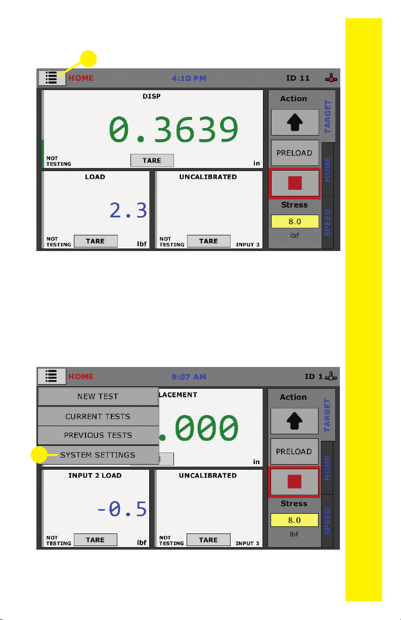
Initial Machine Set-up 6
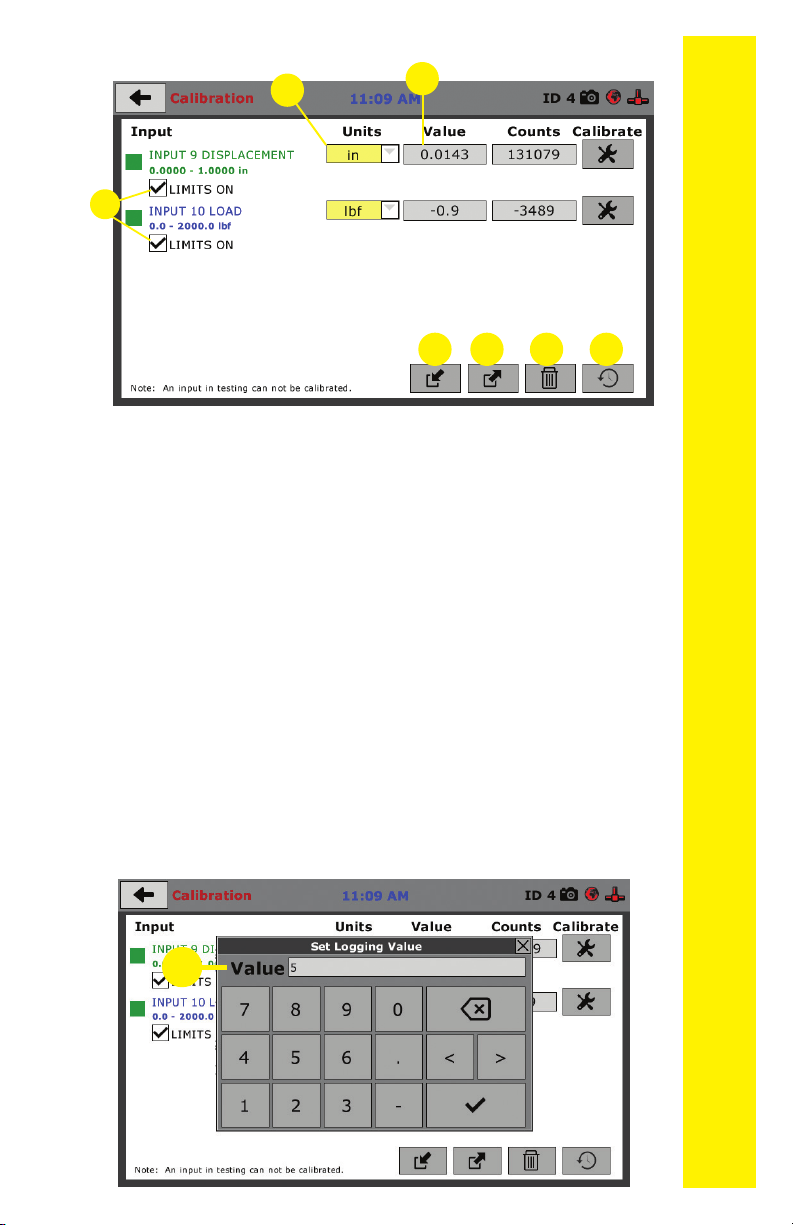
Initial Set-up — Calibration 8
Calibration Input Screen 8
Units 9
Value 9
Export Calibration via USB 10
Import Calibration via USB 10
Delete Calibrations 10
Restore Factory Calibrations 10
Initial Set Up — Date/Time 11
Initial Set-up — Preferences 12
Preferences – General Tab 12
Logger ID 12
Sound 13
Preferences – System Units Tab 13
Ambient Temperature 13
Stress Control Unit 13
Preferences – Specimen Parameters Tab13
Specimen Height 14
Specimen Diameter 14
Preferences – Storage Tab 14
Test Storage Limit 14
Recycled Tests 14
Test Templates 14
Save to USB Check Box 14
Initial Set Up — Network 15
Network Settings Screen 16
DHCP 16
IP Information 16
Local Status 16
Internet Status
16
Initial Set Up — Information 16
System Information 17
Firmware Version 17
IP Information 17
Local Status 17
Internet Status 18
Memory 18
Factory Screen 18
Export Log File 18
Initial Set Up — Contact 18
Contact Information 18
Initial Set Up — Update 19
Update from USB 20
Equipment Setup 22
Installation and Equipment Setup 23
Electrical Connections 23
Power Switch 23
Instrumentation Connections and Setup 24
Rear Instrumentation Panel 24
Network 24
USB Power 24
Instrument Inputs 24
Test Deck Setup 25
Screen Feature Descriptions 26
Consolidation Cells 28
Consolidation Cell Components - Inches 30
Consolidation Cell Components - Metric 31
Calibration of Instrumentation 32
How to Perform a Calibration 32
Export Calibration via USB 32
Test Setup 39
Test Setup 40
Test Setup Wizard – Select Test Type 40
Test Setup Wizard – Sensor Input Selection 41
Test Setup Wizard – Select Logging Values 43
Test Setup Wizard – Select Stop Parameters 44
HM-547-.3F Specications 53
General Warnings 55

QUICK START GUIDE
4
Unpacking
Initial inspection should include checking for physical dam-
age during shipping and obvious external damage to the
product.
Package contents are de ned by your packing list. Each
Loader is con gured according to customer speci cations.
In your inspection, make certain that the contents of your
shipment match the documentation provided by your pack-
ing list.
Place unit on a at, smooth surface and use leveling feet
(supplied) and use a bubble level to ensure that the unit is
level side-to-side and back-to-front.
Installation and Equipment Setup
Electrical Connections
The HM-5475 is equipped with an internal digital switching
power supply, which allows it to be used with most power
con gurations throughout the world. The unit is supplied
with an IEC electrical cord with a standard 110V plug.
The HM-5475 arrives ready for operation. Attach the sup-
plied IEC electrical cord to the machine and plug into a
standard wall receptacle for use in the United States. For
locations other than the U.S., replace the supplied electrical
cord with an IEC cord that has the correct plug for your ap-
plication. The supplied cord can also be used by cutting the
standard plug from the cord and attaching the correct plug.
Power Switch
The Power Switch is located on the upper right hand corner
of the back of the machine, above the electrical cord inlet.
The Fuse Compartment is located between the electrical
cord inlet and the Power Switch. The HM-5475 uses a 10
amp fuse. To begin operation, attach the supplied electrical
cord, plug it in and press the Power Switch.
Fig. 1 Power Switch
Fuse Compartment

QUICK START GUIDE
5
Instrumentation Connections and Setup
Network (1)
Ethernet input for connecting the machine to a local area
network (LAN) and/or the internet.
USB Power (2)
The USB Power port is used for powering a wireless access
appliance for those who want to use a wireless LAN setup.
Instrument Inputs (3)
The panel features four (4) inputs for connecting instrumentation
to the machine. Each input represents a separate channel and has
been assigned and calibrated to a specic instrument for use with
your HM-5475 depending on the test type to be performed.
2
1
3

QUICK START GUIDE
6
Once you have installed the instrumentation into the correct
inputs, your rear panel should look like this:
Below are photos of an instrumentation input and its asso-
ciated plug. Install the plugs into the inputs by lining up the
guide at the bottom of the plug with the slot at the bottom
of the input.
Remember, your HM-5475 ConMatic IPC, Automated
Consolidation Machine includes all the necessary instru-
mentation, which is already calibrated and assigned
to an Input and will not need calibration; however, you
should conrm that the instrumentation has been set
up and calibrated, that you have plugged them into the
correct channel, and that you check with your QC/QA
program to set up a frequency of calibration schedule.
DO NOT RECALIBRATE!
Instrumentation Input Instrumentation Plug
Initial Machine Set Up

QUICK START GUIDE
7
When your HM-5475 is rst turned on, the screen below will
appear.
From this screen, to con rm your machine instrumentation has
been calibrated, navigate to the Calibration section by clicking
the Menu icon in the top left corner of the screen (1).
When you click on this button, you will see a drop-down menu
appear, see below.
Navigate to the bottom of this drop-down menu and click
on System Settings (2). You will see the following screen.
1
2

QUICK START GUIDE
8
Click on the Calibration tab in the top left corner (2). You will
see the following screen.
2
Calibration Input Screen
The Calibration Input Screen (above) is used to monitor and
calibrate instrumentation and assign them to specic chan-
nels of the HM-5475. The Calibration Input Screen provides
a summary of the calibration status of each channel. Please
verify that the sensor range and unit of measure are correct.
A green box at the left of a channel indicates that the chan-
nel has instrumentation assigned to it and that it is calibrat-
ed and ready for use (1).
1
Initial Set Up — Calibration

QUICK START GUIDE
9
Calibration Input Screen, cont.
Each channel has a “Limits On” check box (1). It is recom-
mended that this remains checked to ensure the machine
cannot exceed the design limits of the instrumentation and
damage them. By selecting this option, before the test can
exceed the limits of the sensors, all tests will stop running and
the motor will stop to avoid damaging connected instrumen-
tation.
Note: An input cannot be calibrated during testing.
Units (2)
In this eld, a calibrated instrument will display the units that
were chosen for use at the time of calibration. This eld can
also be used to toggle between English and SI units if the
need arises.
Value (3)
This eld displays the current calibration value. This value
should already be set with 4 decimal point accuracy (1) be-
low. If the instrument is not calibrated, the unit will read “N/A.”
1
23
4
1
6 75

QUICK START GUIDE
10
For the HM-5475, Vertical load = 2,000 lb and vertical
displacement = 1.000”)
Export Calibration via USB (4)
Press this button to select calibrations to export via USB. It
is a good practice to export all your calibrations to a thumb
drive. In case of a problem this practice allows you to recov-
er your calibration data quickly.
Import Calibration via USB (5)
Press this button to import calibrations from a USB drive
into the HM-5475.
Delete Calibrations (6)
Selecting this button will allow the user to delete any of the
desired calibrations from the 5475 memory.
Restore Factory Calibrations (7)
Selecting this button will allow the user to restore the cali-
brations stored in the permanent memory. This is typically
the calibrations set at the factory during nal assembly.

QUICK START GUIDE
11
1
To set up Date and Time settings, return to the System Set-
tings screen and click on the Date/Time Icon. (1)
1
2
3
4
Once the Date/Time icon has been selected the screen
shown below will appear.
Select any of the yellow boxes in the Date row (1) to adjust
the date settings.
Select any of the yellow boxes in the Time row (2) to adjust
the time settings
Select the Clock Style (3) to select either a 24 hour or 12
hour time to show on the top of the touch screen.
Initial Set Up — Date and Time

QUICK START GUIDE
12
This screen is accessed by clicking on the “Preferences”
button. (1)
1
Initial Set Up — Preferences
Click on the Preferences tab (1). You will see the following
screen.
2
1
Preferences – General Tab
The Preferences panel is comprised of four (4) tabs and
defaults to the General tab, see above.
Logger ID (1)
Each machine that is connected to your network requires
a unique Logger ID. These numbers can be assigned any
number between 1-245. In most cases, if you are setting
up a new machine it has been given the Logger ID 1. This
would show in the Logger ID eld. (1). If this number con-
icts with another machine’s Logger ID, one of the machines
will have to be changed to another Logger ID.

QUICK START GUIDE
13
Sound (2)
Checking this box enables or disables audio feedback for
logger events.
Preferences – System Units Tab
This screen is accessed by clicking on the “System Units”
Tab under System Preferences.
1
2
Ambient Temperature (1)
This eld displays the current ambient temperature and
allows you to select desired units (Fahrenheit or Celsius) for
temperature recording.
Stress Control Unit (2)
Click on the desired units you want to use for motor control.
Preferences – Specimen Parameters Tab
This screen is accessed by clicking on the Specimen Param-
eters Tab under System Preferences.
1
2

QUICK START GUIDE
14
Test Storage Limit (1)
This eld allows you to set the number of previously run
tests to be available on the “Previous Tests” screen. This
number can be between 10-50.
Recycled Tests (2)
This refers to previously run tests that are not displayed in
the “Previous Tests” window. These tests are not deleted;
they are recycled for later use. Select this button to view/ex-
port/delete recycled tests.
Test Templates (3)
Select this button to delete test templates that have been
created, but are no longer desired.
Save to USB Check Box (4)
Checking this Box saves the results of a test to USB thumb
drive inserted into the front USB slot on the machine.
Specimen Height (1)
This eld allows you to set the specimen height that will be
used for all testing calculations.
Specimen Diameter (2)
This eld allows you to set the specimen diameter that will
be used for all testing calculations.
Preferences – Storage Tab
This screen is accessed by clicking on the Storage Tab un-
der System Preferences.
1
2
3
4

QUICK START GUIDE
15
A password is required to access the Network Settings.
That password is: 27604.
1
To set up Network settings, return to the System Settings
screen and click on the Network panel. (1)
Initial Set Up — Network

QUICK START GUIDE
16
1
2
3
4
Initial Set Up — Information
Network Settings Screen
The screen above is the Network Settings screen, it provides
information on your IP information and network status.
DHCP (1)
Check this box to enable/disable the Dynamic Host Cong-
uration Protocol (DHCP). If enabled, your machine will pick
up IP information from your router. If disabled, you will need
to manually enter the network information for a static IP,
please consult your network administrator for this.
IP Information (2)
This information will be lled in automatically if the DHCP is
checked, otherwise you will have to manually supply this in-
formation. The IP address must be unique for each machine.
Local Status (3)
This indicates the status of the local network connection,
Connected or Disconnected.
Internet Status (4)
This indicates the status of your Internet connection, Con-
nected or Disconnected.
Note: If you are experiencing issues with any connec-
tions, please contact your IT department for assistance.
Clicking on this panel provides a view of the current status
of the machine. (1)

QUICK START GUIDE
17
Firmware Version (1)
The current version of the machine rmware is shown here. If you
contact product support, you will need to supply this information.
IP Information (2)
This information will be lled in automatically if DHCP is
checked, otherwise you will have to manually supply this in-
formation. The IP address must be unique for each machine.
Local Status (3)
This indicates the status of the local network connection,
Connected or Disconnected.
1
System Information
Below is a view of the System Information screen. It pro-
vides a current status of the machine.
1
24
7
3
5
6

QUICK START GUIDE
18
Contact Information
Below is a view of the Contact Information screen showing
contact information for Humboldt Support and Service.
For quickest response go to this link on our website:
https://www.humboldtmfg.com/support and ll in the
support form. This will provide us with the necessary
information to assist you and you will be added to the next
position in the support cue.
You can also email Humboldt Support at support@hum-
boldtmfg.com or Humboldt Service at service@humboldtm-
fg.com. Please include contact information and a detailed
description of your reason for contact.
Internet Status (4)
This indicates the status of your Internet connection,
Connected or Disconnected.
Memory (5)
This indicates the current status of how much available
memory is being used by the machine
Factory Screen (6)
This is for Humboldt use only.
Export Log File (7)
This button exports a log le from the machine to a USB thumb
drive. Be sure to insert a thumb drive before exporting the le or
you will receive an error message. This le can be helpful in trou-
ble shooting by Humboldt Support.
Clicking on this panel provides contact information for
Humboldt Support and Service(1)
1
Initial Set Up —Contact

QUICK START GUIDE
19
Clicking on this panel provides information on checking for
Updates, performing updates and an update history for the
machine. (1)
1
Initial Set Up — Update

QUICK START GUIDE
20
Update from USB (1)
Software updates for your machine can be downloaded
from the Humboldt website Support Area using a computer.
To access the Software Update area, go to: https://www.
humboldtmfg.com/support/software.php.
Once on this page, click on the Elite Series Firmware tab.
You will see a list of Humboldt Elite Series machines. Click
on the HM-5475 Current Version link and the rmware
update will begin to download to your computer. Once the
download is complete. Load the le onto a USB thumb drive
and insert the thumb drive into the USB port on the front of
the HM-5475. With the USB thumb drive inserted into the
USB port, click on Update from USB (1).
A window will open and you will see a list of Updates. Se-
lect a le to use for your update and click the Select button.
1
1
This manual suits for next models
1
Table of contents
Other Humboldt Test Equipment manuals

Humboldt
Humboldt H-3630A User manual

Humboldt
Humboldt HM-2750 Series User manual

Humboldt
Humboldt H-4165 User manual

Humboldt
Humboldt HM-5030 User manual

Humboldt
Humboldt HM-2850.3F User manual

Humboldt
Humboldt H-4212MH User manual

Humboldt
Humboldt HM-4100A User manual

Humboldt
Humboldt HM-5760.3F User manual

Humboldt
Humboldt HM-5470.3F ConMatic IPC User manual

Humboldt
Humboldt HS-4157 User manual