Starrett SR200 User manual


Table Of Contents
Chapter 1 Using the SR200 with a PC 3.3 Specification for Data Dump 5.5
Introduction to Surface Texture Printing 3.3 Chapter 6 Accessories 6.1
terminology and definitions 1.1 To cancel print: 3.3 Chapter 7 Maintenance 7.1
Surface Texture Definitions 1.1 Chapter 4 Menu Settings 4.1 Calibration 7.1
Parameter Definitions 1.2 Main Menu 4.1 Reference Standard 7.1
Ra 1.2 Cut off 4.1 Sensitivity Check and Adjustment 7.1
Rp 1.2 Evaluation length 4.1 Cleaning the Stylus 7.1
RSm 1.2 Parameters 4.1 Pick-up Skid 7.1
Rz 1.2 Range: 4.3
Rz1max 1.2 Range Selector Table 4.3
Rt 1.2 Print Settings: 4.3
Rmr 1.3 Units: 4.3
RPc 1.3 Filter: 4.3
Rsk 1.3 Dump Mode: 4.3
Rda 1.3 Dump Mode (Using your SR200
Chapter 2 Description 2.1 with a PC) 4.3
The Equipment 2.1 SPC Mode 4.4
Traverse Unit 2.2 Language Settings 4.4
Pick-up Mounting Components 2.3 Chapter 5 5.1
Mounting Bracket 2.3 Making Measurements
Adjustable Support 2.4 Technical Considerations 5.1
Pick-up holder 2.4 Operating Notes 5.1
Connector 2.4 On a horizontal surface 5.1
Pick-up 2.5 On other surfaces 5.1
Mounting 2.6 Cut off: 5.2
Chapter 3 Getting Started 3.1 Evaluation Length: 5.2
Battery 3.1 Table of Cut-off values 5.2
Connecting the Pick-up 3.1 Operating Error Indications 5.2
Making a measurement 3.2 Specification 5.3
Switching the SR200 ON 3.2 RS232 Output 5.3
To cancel a measurement 3.3 Printer Configuration 5.3
Rapp Industrial Sales 724 789-7853

1.1 SR200 Specifications subject to change
Chapter 1
Introduction to Surface Texture terminology and definitions
Surface Texture Definitions
Every components surface has some form of texture which varies according to its structure
and the way it has been manufactured. These surfaces can be broken down into three main
categories: Surface roughness, Waviness and Form. In order to predict a components behaviour
during use or to control the manufacturing process, it is necessary to quantify these surface
characteristics. This is done by using surface texture parameters.
Surface Texture Parameters: Can be separated into three basic types: Amplitude, Spacing
and Hybrid.
Amplitude Parameters: Measures of the vertical characteristics of the surface deviations.
Spacing Parameters: Measures of the horizontal characteristics of the surface deviations.
Hybrid Parameters: Combinations of spacing and amplitude parameters.
Mean Line: Is a least squares line of nominal form fitted through the primary profile where
the areas of the profile above and below this line are equal and kept to a minimum separation.
Profile filters as detailed in ISO11562 define the mean lines for the roughness and waviness
profiles.
Cut-off: A cut-off length (or sampling length) is a filter that uses either electronic (2CR)
or mathematical (Gaussian) means to remove or reduce unwanted data in order to look at
wavelengths in the region of interest.
Bandwidth: Is the ratio of the upper Cut-off (Lc) to the lower Cut-off (Ls).
Sample Length: The profile is divided into sample lengths l, which are long enough to include
a statistically reliable amount of data. For roughness and waviness analysis, the sample length
is equal to the selected cut-off (lc) wavelength. The sample length is also known as the cut-off
length.
Evaluation Length: The length in the direction of the X axis used for assessing the profile
under evaluation. The evaluation length may contain one or more sample lengths. For the
primary profiles the evaluation length is equal to the sample length.
Rapp Industrial Sales 724 789-7853

SR200 Specifications subject to change 1.2
Note: almost all parameters are defined over one sample length, however in practice more than one sample
length is assessed (usually five) and the mean calculated. This provides a better statistical estimate of the
parameters measured value.
Parameter Definitions
Surface texture is quantified by parameters which relate to certain characteristics of the
texture. The SR200 offers the following parameters:
Ra, Rp, Rsm, Rz, Rt, Rmr, RPc, Rz1max, Rsk, Rda
Additional parameters can be analysed by downloading results to optional software.
Ra: Universally recognised, and most used, international parameter of roughness. It is the
arithmetic mean of the absolute departures of the roughness profile from the mean line.
Rp: Maximum profile peak height
Mathematically, the largest peak deviation of the roughness profile from the mean line within a
sampling length.
When more than one sampling length is analysed rp is the mean value of the individual rp
values for each sample.
RSm: The mean spacing between profile peaks at the mean line, measured within the
sampling length. (A profile peak is the highest point of the profile between an upwards and
downwards crossing of the mean line).
Rz: Rz = Rp + Rv and is the maximum peak to valley height of the profile within a sampling
length.
When more than one Sampling Length is analysed Rz is the mean value of the individual Rz
values for each Sampling Length.
Rz1max: Maximum Height of Profile
Highest peak to valley within a sampling length. When measured over several sampling lengths
the largest individual sampling length value is taken.
Also known in the past as Rymax, Ry, Rmax or Rti
Rt: Total Height of the Profile.
Maximum Peak to Valley Height of the Profile in the Assessment (evaluation) Length (ln).
Rapp Industrial Sales 724 789-7853

1.3 SR200 Specifications subject to change
Rmr: Material Ratio is the length of bearing surface (expressed as a percentage of the
evaluation length ln) at a depth below the highest peak.
Replaces tp% - Bearing Ratio as defined in ISO 4287 - 1984
RPc: Peak Count
The number of local peaks which project through a selectable band centred about the mean line
or a line parallel to it. The count is determined only over the evaluation length though the results
are given in peaks per cm (or per inch)
Known as Pc before 1997
Rsk: Skewness
Rsk is a measure of the symmetry of the profile about the mean line.
This parameter indicates whether the spikes on the surface are predominately negative or
positive or if the profile has an even distribution of peaks and valleys.
Rda: R Delta a or Rda or RDa - Arithmetical Mean Slope
Arithmetical Mean Slope of the Profile within the Sampling Length.
Rapp Industrial Sales 724 789-7853
SR200 Specifications subject to change 2.1
Chapter 2
Description
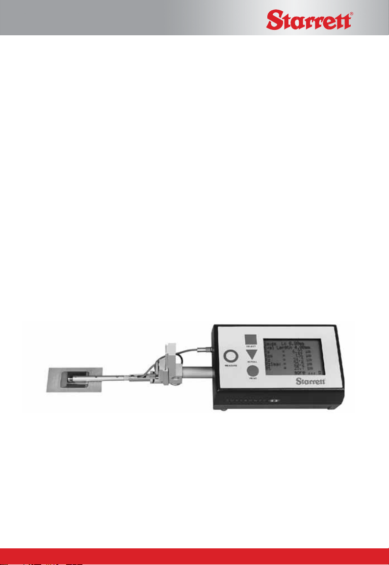
The SR200 is a portable, self-contained instrument for the
measurement of surface texture and is suitable for use in both the workshop and laboratory.
Parameters available for surface texture evaluation are:
Ra, Rz, Rt, Rp, Rmr, RPc, Rv, Rz1max, Rsk, Rda
An explanation of the surface texture parameters evaluated by this instrument is given in
Chapter 1.
The parameter evaluations and other functions of the instrument are microprocessor based.
The measurement results are displayed on an LCD screen and can be output to an optional
printer or computer for further evaluation.
The instrument is normally powered by an alkaline non-recharge-able battery. If preferred, an
optional power adaptor can be used
Figure 1
The Equipment
The standard SR200 includes:
• 1 Traverse unit
• 1 Standard Pickup
• 1 Reference Specimen
• 1 Pickup cable
• 1 Screwdriver
• 1 Battery
Note: certain items described in this handbook are optional and may not form part of your particular system.
Rapp Industrial Sales 724 789-7853

2.2 SR200 Specifications subject to change
Traverse Unit
The top panel of the traverse unit carries a membrane type control panel and a liquid crystal
display. The unit houses the electronics for controlling the measurement sequence, computing
the mea-
surement data and outputting the results to the display, or to the
RS232 port for use with a printer (when included) or to a com-
puter, for further analysis.
The unit also contains a drive motor which traverses the pickup
across the surface to be measured. The measuring stroke always starts from the extreme
outward position. At the end of the measurement the pickup returns to this position ready for
the next
measurement. The traverse length is determined from selections of cut-off or length.
Figure 2
Pick-up
Connector Select Key Display
Battery Compartment
RS232 Connector
Measure key Scroll key Print key
Battery
Rapp Industrial Sales 724 789-7853

SR200 Specifications subject to change 2.3
Pick-up Mounting Components
The pick-up is fastened to the drive shaft by the following means:
Mounting Bracket. This is clamped to the drive shaft by means of a knurled knob.
Although normally used upright, as shown in figure 3, it can be turned to angle the pick-up or to
take it off the centre line, as shown in figure 3a. It can also be mounted side-ways on the drive
shaft, when the right angle pick-up is in use.
Figure 3: pick up mounting
Pick-up
Insert Extension
rod here Clamp Drive Shaft
Connector Adjustable
Pick-up Support Mounting Bracket
Pick-up Holder Mounting Bracket
Clamp Screw
Use this mounting position when the right angled pick-up is used
Rapp Industrial Sales 724 789-7853

2.4 SR200 Specifications subject to change
Figure 3a Figure 3b
Adjustable Support: This can be clamped at any position on the slide of the mounting
bracket to provide pick-up height adjustment.
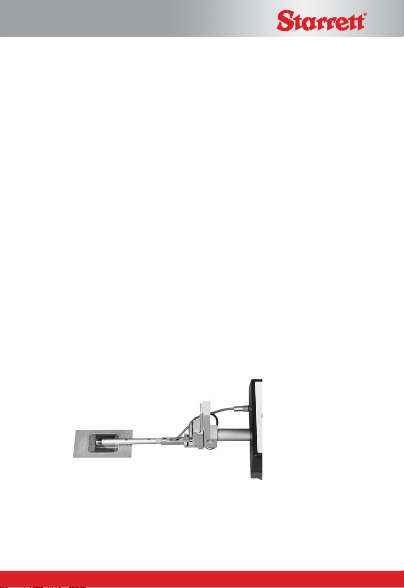
Pick-up holder: This fits into the crutch of the pick-up support and is held in place by a
spring plunger. A biased holder, when used as shown in figure 3, exerts a biasing force on the
pick-up (depending on which way the holder is inserted into the support crutch). It can also be
used to position the pick-up directly underneath the display unit, as shown in figure 4.
Figure 4
The holder will hold the pick-up at right angles to the drive shaft when it is pivoted away from
the surface (eg while changing the work piece).
Connector: The connector of the pick-up lead is screwed into the end of the pick-up and
is then inserted into the end of the pick-up holder, with the lead coming out through the slot
Rapp Industrial Sales 724 789-7853
SR200 Specifications subject to change 2.5
in the holder. It is advisable to connect the lead to the display-traverse unit first and then the
pick-up. To connect the pick-up to the display-traverse unit: the pick-up has 2 threaded ends
with location pins. Insert the location pin securely into the SR200 body and tighten the threaded
collar.
When the extension rod is used, the short pick-up lead is not required and the end of the rod
itself is inserted into the holder.
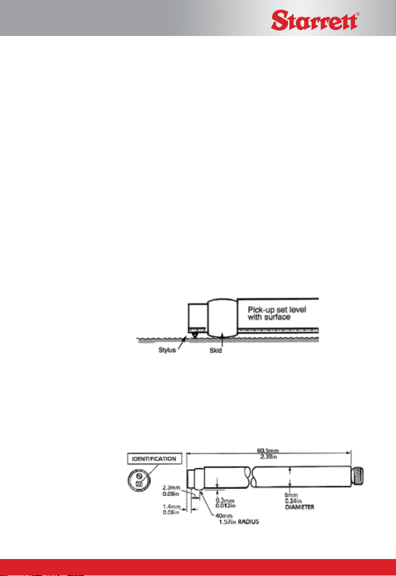
Pick-up: The pick-up is a variable inductive type transducer, which is supported on the
surface to be measured by a skid, a curved support projecting from the underside of the pick-
up in the vicinity of the stylus. As the pick-up traverses across the surface, movements of the
stylus relative to the skid are detected and con-verted into a proportional electrical signal. The
radius of curvature of the skid is much greater than the roughness spacing. This enables it to
ride across the surface almost unaffected by the roughness, and provide a datum representing
the general form of the surface. Even so, where the waviness is widely spaced it will be
necessary to use the pick-up with shoe, in conjunction with the 2.5mm (0.1in) cut-off.
Figure 5: the pickup is supported on the workpiece by the skid
There are several different types of pickup available designed for different applications, details
are given in the Accessories section of this handbook. They differ only in the stylus tip radius,
the dimensions of the housing or position and the shape of the skid. The stylus material in all
the pickups is diamond for low wear. The skids of the standard pickups are of red ruby.
Figure 6. Standard pick-up dimensions
Rapp Industrial Sales 724 789-7853
2.6 SR200 Specifications subject to change
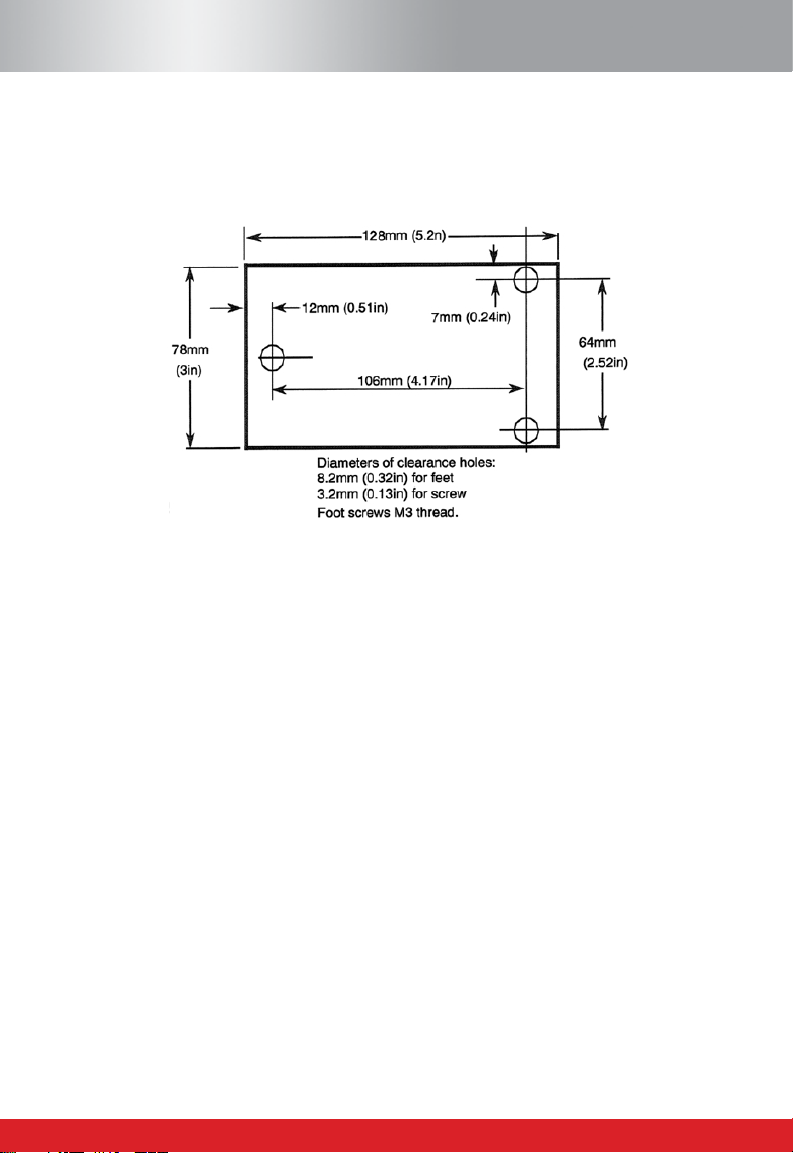
Mounting: On a flat surface the display-traverse unit can be supported on its three feet.
If a user wishes to make his own mounting bracket for the unit, the dimensions of the fixing
holes are shown in figure 7.
Figure 7
Rapp Industrial Sales 724 789-7853
SR200 Specifications subject to change 3.1
Chapter 3
Getting Started
Battery
To insert a battery, open the compartment by sliding the door to the right and remove the door
from the unit. Insert the battery, with the terminals positioned as shown in the diagram on the
floor of the battery compartment.
Connecting the Pick-up
Plug the lead into the socket on the front of the unit and mount the pick-up as follows: The
connector of the pick-up lead is screwed into the end of the pick-up and is then inserted into
the end of the pick-up holder, with the lead coming out through the slot in the holder. It is
advisable to connect the lead to the display-traverse unit first and then the pick-up. To connect
the pick-up to the dis-play-traverse unit: the pick-up has 2 threaded ends with location pins.
Insert the location pin securely into the SR200 body and tighten the threaded collar.
Rotate the pick-up to bring the stylus vertical; this can conveniently be done with reference to
the identity number engraved at the end of the pick-up.
Position the Pickup stylus on the component to be measured, with the stylus parallel to the
component (see figure 8 below). Ensure that the stylus tip is in contact with the surface (this
can be verified by checking that the identity number engraved at the end of the pick-up is
vertical). The skid should also be in contact with the surface.
Figure 8
Rapp Industrial Sales 724 789-7853

3.2 SR200 Specifications subject to change
Making a measurement
Note 1: If the pickup has been changed or the instrument is being used for the first time, the instrument
should be calibrated (see Chapter 7).
Note 2: Successful use of the SR200 will only be possible if it is operated on a surface free from external
vibration - see also operating notes in Chapter 5.
Switching the SR200 ON
Pressing the SCROLL key brings the display on and the previously selected set-up is
displayed (provided power has been continuously present). The display is automatically turned
off if the instrument is not used for 30 seconds.
If the battery is dead or has been removed, the previously selected set-up is lost. When a
battery has been replaced and the SCROLL key is pressed, the start up message will display
for 2 seconds and then the default settings are restored.
The default settings are
Parameter: Ra
Cut-off: 0.8mm
Evaluation length: 4.0mm
Range: 100mm
Data dump evaluation length: 4.0mm
Data dump range: 100mm
No parameter/graph selected for printout
Language English
Filter Gaussian
If the user wishes to change any of these settings, this can be carried out using the SCROLL
and SELECT keys (see Chapter 4 for more detail)
Press the MEASURE key. When the measurement is completed the pickup returns and the
results are displayed on the screen (see example below):
GaussLc 0.80mm
Eval Length 25.0mm
Ra = 0.00µm
Rz = 0.00µm
Rt = 0.00µm
Rp = 0.00µm
RSmm = 0.00µm
more...>
Rapp Industrial Sales 724 789-7853

SR200 Specifications subject to change 3.3
If multiple parameters have been selected they may not fit on the display. To continue viewing
the remaining results, click on the SELECT key.
To cancel a measurement
If Measure is pressed during a traverse, a stop and reversal without measurement will occur
and Measurement Cancelled is displayed.
Using the SR200 with a PC
If the SR200 is connected to a PC then measurements will be taken in dump mode, which
is selected using the SCROLL and SELECT keys from the main menu (see next
chapter for full set-up details). Position the Pickup stylus on the component to be measured.
Measurements are then activated from the software on the PC. When the measurement is
completed the pickup returns and the results are dumped directly to the PC. During transfer of
the measurement data the message Data Dumping is displayed.
When the data dump is completed, the dump menu still remains active. From the displayed
menu, values of evaluation length and range can be changed and further measurements for
data dump can be made (see next chapter for further details).
Printing
PRINT key: pressing this key causes the evaluated measurement data to be output to the
RS232 port. When a printer is connected, a printout of all the parameters selected in the print
menu is made.
If SPC has been selected (see chapter 4) the heading is disabled.
Where the profile is longer than 80cm the printout will stop after 80cm. Pressing PRINT key
can print the next 80cm. The printout will start from the beginning of the profile if SELECT is
activated.
If no legal surface data is stored, the error message “Measure before print” is displayed.
To cancel print
Pressing the PRINT key during printout (before display has updated to Main menu state)
stops the printout and “Printer cancelled” is displayed for 2 seconds. The normal update to
Main-state then continues.
Rapp Industrial Sales 724 789-7853

4.1 SR200 Specifications subject to change
Chapter 4
Menu Settings
The operation of the SR200 is based on making selections from menus presented on the liquid
crystal display. Two menu states exist, these are: Main Menu and Data Dump Menu. The Data
Dump menu is accessed via the Main Menu and is used when connecting to a PC.
Main Menu
The Main Menu (accessed by pressing the Scroll key) is used to make the following selections:
CUT-OFF
EVALUATION LENGTH
PARAMETERS
RANGE
PRINT SETTINGS
UNITS
FILTER
DUMP MODE
The SCROLL key is used to cycle through these options and the SELECT key is used to
confirm the set up screen required. For a chart of default settings see Chapter 3.
Cut Off:
To select the cut-off required, select the Cut-off option from the main menu. Press the SCROLL
key to toggle through the cut-off options until the required cut-off is highlighted on the
screen, then press the SELECT key. See chart in chapter 5 forfurther information.
Evaluation Length.
To select the evaluation length required, select this option from the main menu. Press the
SCROLL key to toggle through the evaluation length options until the required length is
highlighted on the screen, then press the SELECT key.
The evaluation length options are determined by the cut-off length selected.
Parameters:
select the Parameters option from the main menu. A list of the parameters available will appear
Rapp Industrial Sales 724 789-7853
SR200 Specifications subject to change 4.2
on the screen (see below). Press the SCROLL key left to right across the columns then
press the SELECT key for each parameter required (multiple selections can be made). The
SELECT key is also used to de-select a parameter.
Ra RSm
Rz Rz1max
Rt Rsk
Rmr > > > settings
Rpc > > > settings
Exit
When selecting the Rmr and Rpc parameters, additional settings need to be specified. SCROLL
onto “Settings” then click on the SELECT key. The following screen will appear:
Rmr settings
Mr % + Offset
Mean line + Offset
Exit
The SCROLL key will cycle through ‘Mr% + Offset’, ‘Mean line + Offset’ and ‘Exit’. The
SELECT key will allow the alteration of one of the 2 settings or, if Exit is highlighted, will
return to the main parameter selection screen.
Pressing SCROLL will step the cursor (or highlighted character) through the 3 decimal digits
of the percentage, then the sign and 3 decimal digits of the offset and then to OK. Pressing
SELECT will change the sign/digit - keep pressing SELECT until the required figure is
reached. Pressing SCROLL saves the change and moves the cursor along to the next
decimal digit. When complete Select OK to return to the previous menu.
Rmr Settings
Mr% 001%
Offset +00.0µm
OK
The following screen is displayed for Rpc settings and is amended in the same way as above.
Rpc Bandwidth
00.0µm
OK
Rapp Industrial Sales 724 789-7853

4.3 SR200 Specifications subject to change
Range:
Allows the user to scroll through the range options. The most common settings are as follows:
For surfaces <10 micron peak to valley- select range of 10µm
For surfaces <100 micronpeak to valley- select range of 100µm
For surfaces <300 micron peak to valley- select range of 300µm
Range Selector Table
Parameter Resolution Resolution Resolution at 10µm rangeat 100µm rangeat 300µm range
Ra 0.01µm 0.01µm 0.1µm
Rp 0.01µm 0.1µm 1.0µm
Rz 0.01µm 0.1µm 1.0µm
Rz1max 0.01µm 0.1µm 1.0µm
Rt 0.01µm 0.1µm 1.0µm
Rmr 0.1% 0.1% 0.1%
RPc 1 decimal point 1 decimal point 1 decimal point
Rsk 0.001µm 0.001µm 0.001µm
Rda 0.1 deg 0.1 deg 0.1 deg
Rsm 1.0µm 1.0µm 1.0µm
Print Settings:
Allows selection of print options. User can choose to print any combination of graph,
parameters and header information. The scale of the graph can also be selected. SCROLL
through and press the SELECT key for each item required - a tick will appear alongside the
item.
Units:
Allows imperial or metric units to be selected.
Filter:
Allows filter options of either Gaussian or 2CR (see explanation in Chapter 1).
Dump Mode:
This menu mode is used if connecting the SR200 to a PC (see below)
Dump Mode (Using your SR200 with a PC)
If using the SR200 with a PC you will need to select the DUMP MODE option from the main
menu. Scroll to Dump mode ON. Each time the SR200 is switched on, the following dump
mode menu options will be available:
Rapp Industrial Sales 724 789-7853
SR200 Specifications subject to change 4.4
EVALUATION LENGTH
RANGE
UNITS
FILTER
DUMP MODE
All other settings are carried out via the PC.
SPC Mode
If SPC is required, this can be switched on by pressing the PRINT and SCROLL key
down simultaneously. The following warning screen will appear:
Warning
Changes to the following settings
are for advanced functions only
Quit OK
Selecting OK displays the Select language and select SPC mode screen. Select the SPC Mode
then SCROLL will toggle the mode between ON and OFF. When SELECT is pressed with
OK selected the previous screen will be shown again.
S PC ModeON
OK
Language Settings
The default on the SR200 is English Language. If the user wishes to select other languages,
press the PRINT and SCROLL key down simultaneously. The following warning screen
will appear:
Warning
Changes to the following settings
are for advanced functions only
Quit OK
Rapp Industrial Sales 724 789-7853

4.5 SR200 Specifications subject to change
Selecting OK displays the Select language and select SPC mode screen.
Select Language
Select SPCmode
Quit
SCROLL down the options and SELECT
Select Language
English
Français
Deutsch
Italiano
OK
SCROLL down the list of languages with and SELECT . This selection will remain as the
default unless power is lost (eg battery is removed).
Rapp Industrial Sales 724 789-7853
Table of contents
Other Starrett Test Equipment manuals

Starrett
Starrett MTH-550 User manual

Starrett
Starrett SR160 User manual

Starrett
Starrett SR300 User manual

Starrett
Starrett MTH-330 User manual

Starrett
Starrett 3840 Series User manual

Starrett
Starrett MTH-110 User manual

Starrett
Starrett SR160 User manual

Starrett
Starrett SR160 User manual

Starrett
Starrett DFC-2 User manual
Popular Test Equipment manuals by other brands


Sibata
Sibata MT-05U Operation manual

Honeywell
Honeywell BW MicroDock II Quick reference guide

Huvitz
Huvitz CDC-1 user manual

Tektronix
Tektronix TBS2000 Series Safety and installation instructions

Hella Gutmann
Hella Gutmann CSC-Tool operating instructions

ULTIMATE SPEED
ULTIMATE SPEED UAWSB 2 B1 Operation and safety notes