SSD Statiron DZ4 User manual
Instruction Manual
Static Field Meter STATIRON
DZ4
Thank you for purchasing the Statiron DZ4 Please read this manual before using the
product in order to fully understand its functions Also make sure to store this manual so
that it can be referred to in the future
Functions
The static field meter Statiron DZ4 is a portable static electrical potential meter with digital readout, for measuring
the electrical potential of charged objects
When measuring fluctuating static electricity, you can temporarily hold an indicated value, and check maximum
voltages in the MAX mode
Characteristics
1 Enables you to measure surface potentials of charged bodies without coming into contact
2 Enables you to take measurements in narrow locations by rotating the sensor head
3 With the optional ion balance plate, you can carry out ionizer balance checks
SHISHIDO ELECTROSTATIC, LTD

Safety Precautions
This device is a precision electrical instrument For the sake of safety, be sure to follow the
instructions described in this manual mark are precautions that must be followed in order
to use the product safely
This device does not conform to explosion-proof specifications Do not install it
in locations where flammable gases or solvents are handled, such as painting
booths etc Doing so may result in fire or explosion
This device is a precision electrical instrument Avoid installing it in wet, oily,
hot, and humid locations In particular, avoid locations of high humidity and
condensation There is a possibility of fire due to breakdown
Installation
●
Do not use this device in the following locations, as doing so may cause malfunctions
・ Locations subject to high or low
temperature, or high humidity
・ Dusty locations
・ Locations where the device may be
exposed to organic solvents such as
thinner
・ Locations where the device may be
exposed to corrosive gas
・ Locations subject to flames or
explosions
・ Locations subject to frequent vibrations
・ Locations subject to sudden changes in
temperature or humidity
・ Locations subject to condensation
・ Locations where the device may be
exposed to water or oil
Maintenance
Regularly remove any built-up dirt etc from the optional ion balance plate Built-up dirt can
cause insulation faults
Make sure to turn the main power of the device OFF before cleaning
Handling
Make sure to connect the earth wire to an appropriate place Accurate measurements are not
possible if the earth wire is not connected
To obtain accurate measurements, measure at an appropriate distance from the charged
object
Do not touch or insert foreign materials into the sensor portion of this device
Do not blow ionized air directly into the opening of this device
Do not place heavy objects on the LCD display of this device
Do not disassemble or modify the device
The device may affect medical devices such as hearing aids or pacemakers
Do not insert any foreign objects into the device Doing so may result in a short circuit or
current leakage, and cause fire or electrocution
The battery discharges a small amount of electricity even when the device is turned off If you
do not intend to use this device for an extended length of time, remove the battery
If the device emits any abnormal odors or sounds, smoke, or heat, turn OFF the main power
immediately, and contact your point of purchase Failure to do so may result in fire or a short
circuit
Do not remove name plates or labels
Do not do anything with the device that is not described in this manual
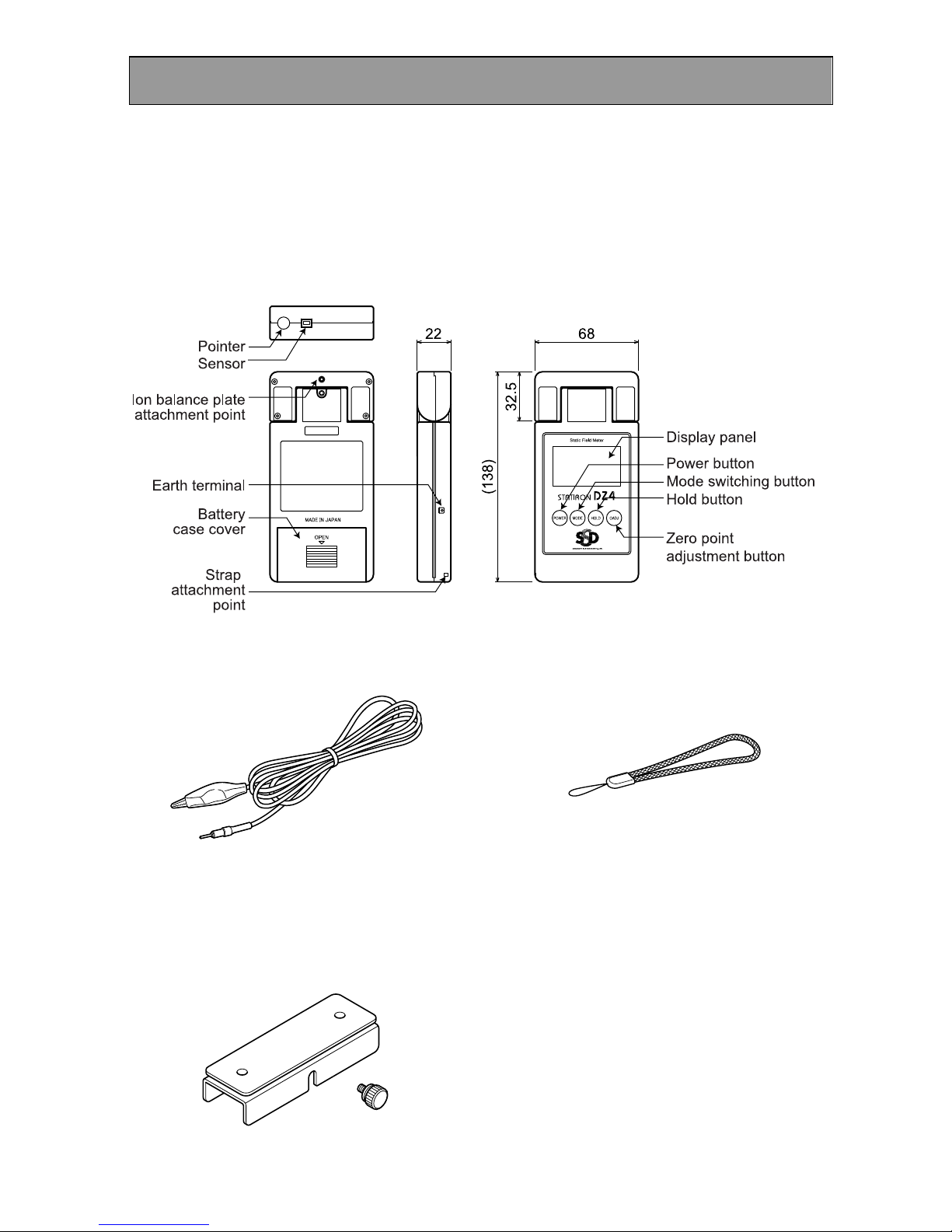
Items Included With the Device
Confirm that the following items are included with the device before using it for the
first time
Instruction manual/warranty x 1 (this document)
Main Device
Earth Lead (x 1)
Strap (x 1)
Battery (006P type 9V alkaline dry cell battery) x 1
Soft case (Model number: ODZ4-SFTCS) x 1
Ion Balance Plate (optional)
(Model number:
ODZ4-GNDCAL)
(Model number:
ODZ4-STRAP)
(Model number: ODZ4-PLT)
Important Points About Taking Measurements
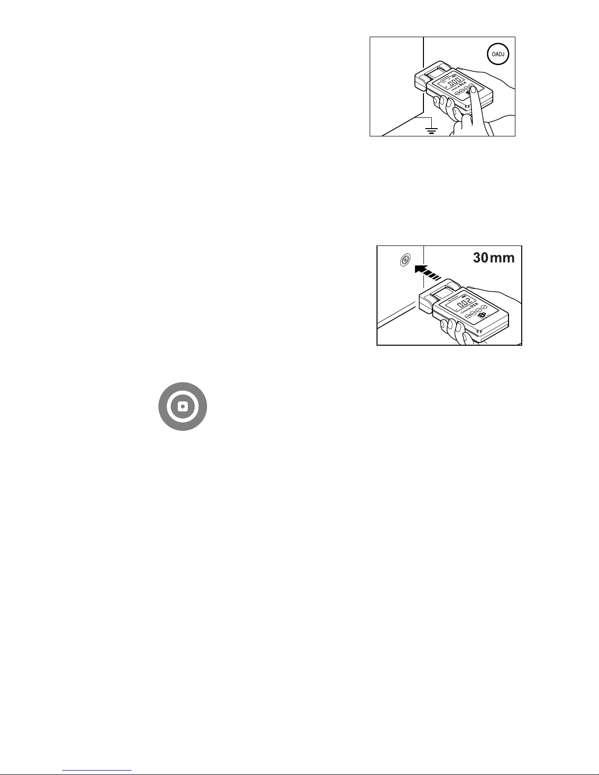
Grounding
If the user's body retains an electrical charge, or highly accurate measurements are
required, ground the earth terminal of this device Also, if the charged object is expected to
have a large charge, be sure to ground the device to avoid breakdown due to discharge
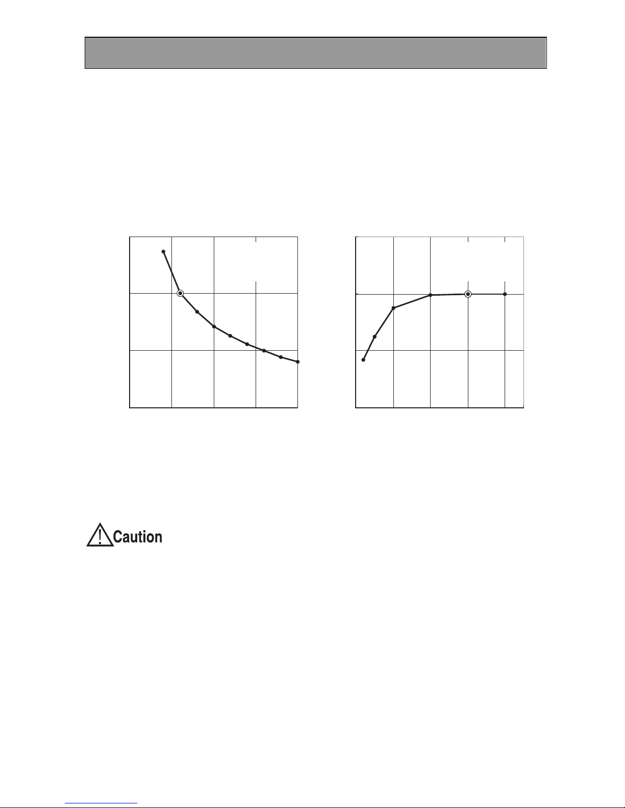
Adjusting the Measurement Distance
The strength of the electrical field of a charged object changes with the distance between
the charged object and the sensor portion of the measuring instrument This device has
been calibrated with a distance of 30mm between a test charged object (200mm2 metal
plate) and the meter Consequently, when measuring it is necessary to conform to a
measuring distance of 30mm Move the meter so that the illuminated point on the charged
object emitted by the pointer (red LED) is sharpest If such a distance cannot be attained,
correct the potential reading according to Figure 1
If the distance is more than the recommended measuring distance of 30mm, and the
displayed potential exceeds 19 99kV, do not move the meter any closer to the charge
object
If the meter is too close to the charged body, there is the danger of an
electrical discharge This may cause a breakdown of the device
Influence of the size of the charged object
The measured potential changes according to the field strength concentrated in the
electrode of the sensor portion of the meter and the size of the charged object In particular,
if the charged object is smaller than the test charged object used during calibration
(200mm2), there is a large discrepancy in the measured value and an error can occur in the
resulting value if this is the case, you can roughly correct the value according to Fig 2
Influence of other objects
If there are other objects near or behind the charged object, the displayed measurement is
smaller than the actual potential If this is the case, correct the measurement in light of the
shape of the electrical field, or put as much distance as possible between the charged
object being measured and other objects
Influence of charged particles etc.
Powerfully charged objects impose a charge on particles and create an ionic space If
charged particles etc adhere directly to the electrode of the meter, measurement errors will
occur This phenomenon occurs when a large amount of fluff adheres to the charged object
or large amounts of dust are in the vicinity
150
100
50
0
150
100
50
010.0 25.020.015.010.0
d (cm)
Vo / Va x 100 (%)
Vo / Va x 100 (%)
L (cm)
7.55.02.5
L = 20 cm
Va: base voltage
A = L x L
d = 3 cm
Va: base voltage
A = L x L
(Fig 1) Relationship between measuring distance d and
indicated value Vo of surface electrometer
(FIg 2) Relationship between size A (length L of
one edge) of (square) charged object and
indicated value Vo of surface electrometer
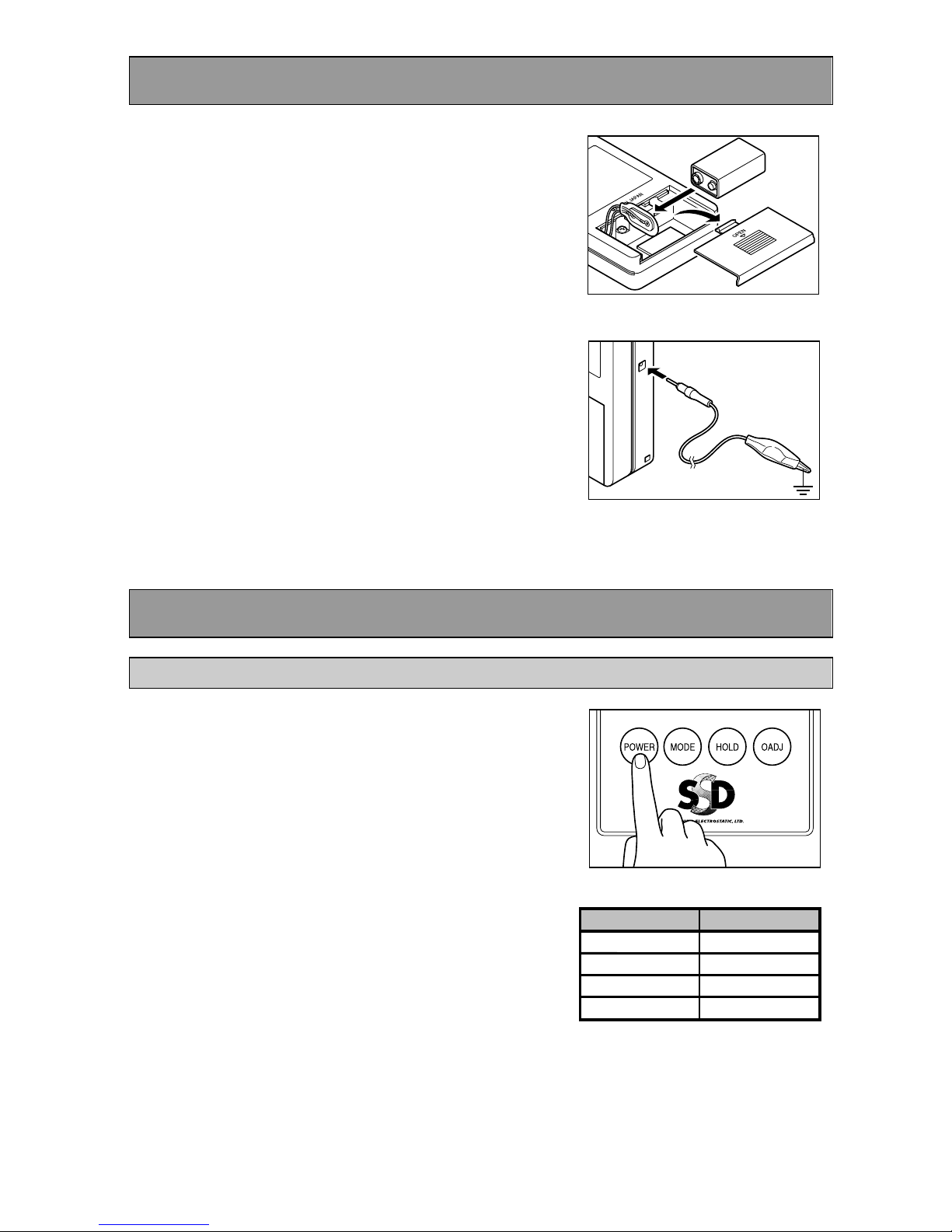
Preparation
1. Insert the batter .
Remove the battery case cover and insert
a 9 volt dry cell battery Replace the cover
carefully, taking care to keep the battery
leads clear of the cover
2. Connect the earth lead to the
earth terminal, and reliabl
ground the earth lead.
Connect the earth lead securely to the
terminal, and connect the clip on the end
of the earth lead to a grounded object To
obtain accurate measurements, the earth
terminal must be grounded
Measurement Procedure
Measuring Static Electricity
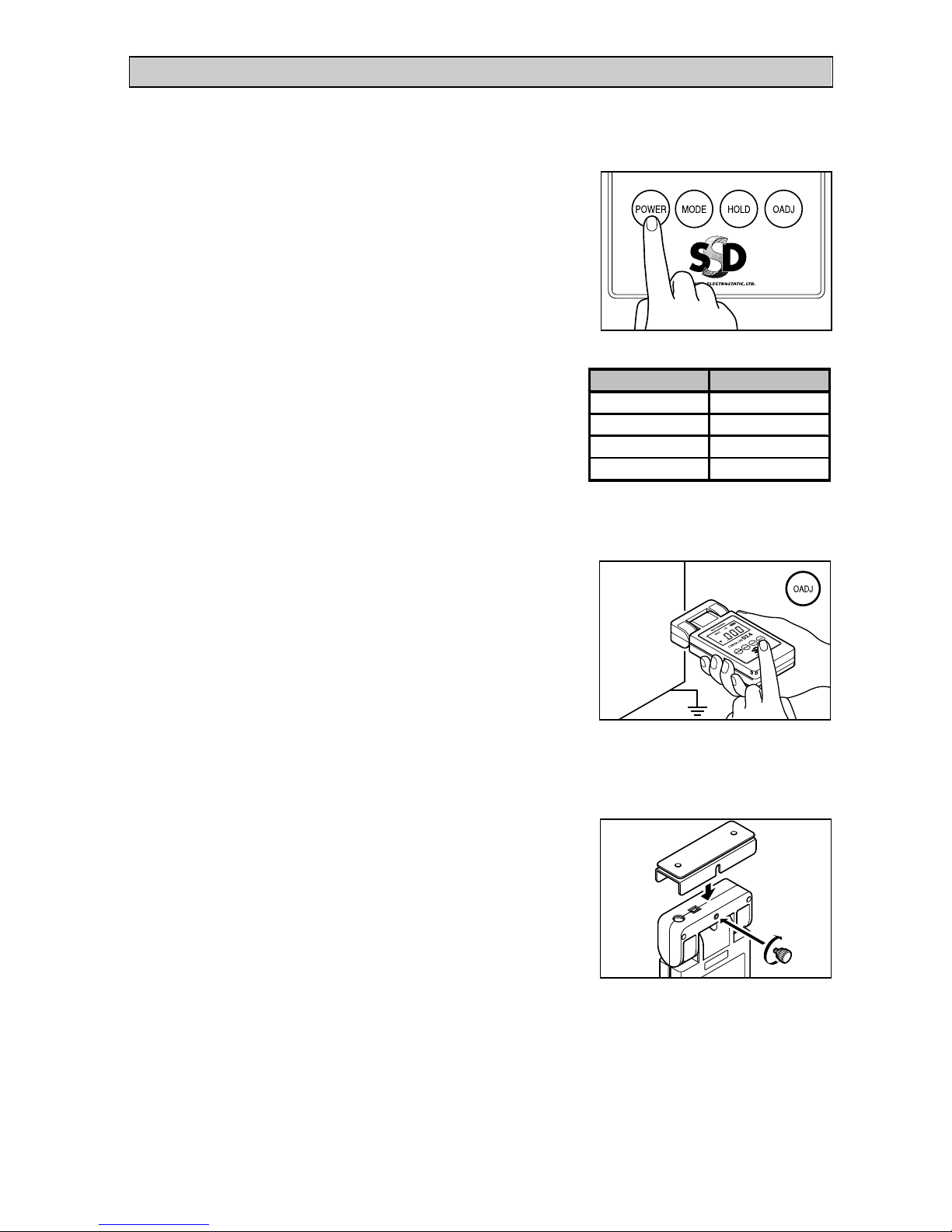
1. Turn the meter on.
Press the POWER button for more than
one second, until you hear a beep
2. Set the mode ou want to use.
Each time you press the mode button, the
meter scrolls through the modes in the
order shown in the table on the right To
measure potentials, use the normal mode
Mode
ModeMode
Mode
Panel display
Panel displayPanel display
Panel display
Normal Mode
(None)
MAX Mode
MAX
I.B + MAX Mode
MAX I.B
I.B Mode
I.B
3. Zero point adjust the meter.
Point the sensor at a grounded object and
press the 0ADJ button
NOTE
Zero point adjustment is reset when
you turn the meter off
4. If ou want to measure a maximum potential, use the MAX
mode.
Refer to step 2 for how to set modes
5. Point the sensor at the charged
object, and graduall bring the
meter closer to the object.
The distance between the sensor and the
charged object should be 30mm At about
30mm, the red LED beam (pointer) cast on
the charged object should look like the
image in Figure 3
(Fig 3) Red LED mark
NOTE
If the recommended measuring distance of 30mm cannot be attained, do not
bring the meter any closer if the potential displayed exceeds 19 99kV Doing
so may cause damage to the meter
If the display panel blinks "1", the charged voltage has exceeded the
measurable range (over-range) If this occurs, stop measuring immediately, as
this may cause damage to the meter
6. The value on the displa panel is the measurement result (unit:
kV).
7. In normal mode, ou can temporaril hold the measured value
b pressing the hold button.
If you press the hold button again, the stored value is removed
You cannot use the hold function in MAX mode
8. To turn the meter off, press the POWER button for more than 1
second.
Measuring Ion Balance
By attaching the optional ion balance plate (sold separately) to the meter, you can measure
ion balance (offset voltage)
1. Turn the meter on.
Press the POWER button for more than
one second, until you hear a beep
2. Set the mode ou want to use.
Each time you press the mode button, the
meter scrolls through the modes in the
order shown in the table on the right To
measure offset voltages, use the I B mode
3. Zero point adjust the meter.
Point the sensor at a grounded object and
press the 0ADJ button
NOTE
Zero point adjustment is reset when you turn the meter off
4. Attach the ion balance plate to
the meter.
Firmly screw the ion balance plate onto the
meter with the screw provided, making
sure that it is centered and there is no gap
5. If ou want to measure the maximum value of an offset voltage,
use the MAX I.B mode.
Refer to step 2 for how to set modes
Mode
ModeMode
Mode
Panel display
Panel displayPanel display
Panel display
Normal Mode
(None)
MAX Mode
MAX
I.B + MAX Mode
MAX I.B
I.B Mode
I.B

6.
Point the ion balance plate at the
measurement location.
The potential on the ion balance is
measured
NOTE
If the display panel blinks "1", the charged voltage has exceeded the
measurable range (over-range) If this occurs, stop measuring immediately, as
this may cause damage to the meter
7. The value on the displa panel is the measurement result (unit:
kV).
8. In I.B mode, ou can temporaril hold the measured value b
pressing the hold button.
If you press the hold button again, the stored value is removed
You cannot use the hold function in MAX I B mode
9. To turn the meter off, press the power button for more than 1
second.
Adjustment and Maintenance
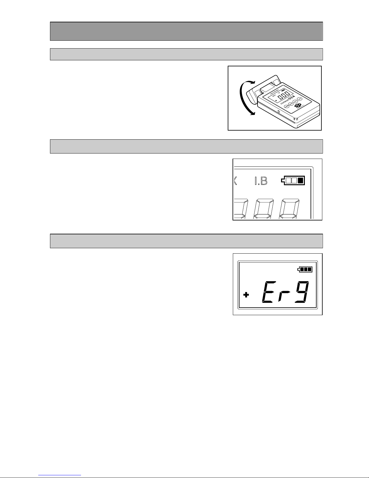
Rotating the Sensor Head
You can rotate the sensor head of the meter This
enables you to easily take measurements in
narrow locations etc that were previously difficult
to access
The sensor head rotates in 45° increments When
rotating the head, stop at angles where the sensor
head clicks into place
Battery Indicator
The remaining battery charge is displayed on the
upper right of the display panel
When the battery charge icon shows one unit left,
replace the battery
Error Display
The signal detection method of the meter is an
oscillating chopper method
If for some reason the sensor stop oscillating, an
error message like that shown in the illustration on
the right is displayed, and the meter emits a
beeping sound every second
If this occurs, restart the meter If the error
message continues to be displayed after restarting
the meter a number of times, the sensor may be
faulty Contact the sales office where you
purchased the product
Troubleshooting
If the device does not operate correctly, it may be the result of one of the following
The display panel is not active when the power is turned on
Cause 1 The battery has not been installed, or the positive and negative
terminals have been connected the wrong way around
Remedy 1 Correctly install the battery
Cause 2 The battery has been completely drained
Remedy 2 Replace the battery with a new one
The display panel displays correctly, but does not zero
Cause 1 Zero point adjustment is incorrect
Remedy 1 Perform zero point adjustment again
Cause 2 Structural components close to the sensor are charged
Remedy 2 Wait until the charge in the components has attenuated
The display does not change even when approaching a charge object
Cause 1 The meter is holding a maximum value in MAX mode or MAX I B
mode
Remedy 1 Press the mode button to switch modes
Cause 2 The meter is holding a measured value in normal mode or I B mode
Remedy 2 Press the hold button and start measuring again
Cause 3 The sensor is faulty
Remedy 3 If an error message is displayed or you cannot hear an oscillating sound
from the sensor, the sensor must be replaced Contact the sales office
where you purchased the product
Specifications
Signal detection method Oscillating chopper method
Display refresh frequency 0 5 seconds
Measurable potential range Normal mode: 0 00 - ±19 99kV (resolution: 0 01kV)
I B mode: 0 000 - ±1 999kV (resolution: 0 001kV)
Continuous operating limit Approximately 10 hours (with alkaline battery)
Measuring distance 30 mm (between object being measured and sensor)
Measuring distance adjustment Red LED beam focusing method
Sensor head rotation angle 180° (stops every 45°)
Display LCD display with built-in backlight
Polarity display + polarity/- polarity display
Mode switching Switch modes by pressing MODE button
Battery check Remaining charge displayed in display panel
Battery DC9V alkaline rectangular dry cell battery 006P
Operating temperature/ humidity
range 0 - +40℃, 20 - 70%RH, non-condensing
Dimensions 68 mm x 22 mm x 138 mm (W x D x H)
Weight Approximately 230g (including battery)

Warrant
Valid for: 1 year after delivery
Product
name Static Field Meter STATIRON
Model DZ4 Serial
number
Date of
Delivery Inspection
Stamp
1 If any malfunctions or damage occur to the product due to any of the following reasons, a
charge will be incurred for repairing or replacing the product
2 Malfunctions or damage occurring to the product due to misuse or improper storage
・ Malfunctions or damage occurring to the product due to repairs or modifications
conducted by a party other than SHISHIDO ELECTROSTATIC or a company specified
by SHISHIDO ELECTROSTATIC
・ Malfunctions or damage occurring to the product due to fire, natural disasters, or other
acts of providence
・ Other malfunctions or damage occurring to the product deemed not to be the
responsibility of SHISHIDO ELECTROSTATIC
For any queries relating to the product, contact the sales office where you purchased the
product
SHISHIDO ELECTROSTATIC, LTD.
http://www.shishido-esd.co.jp/
HEAD OFFICE MARUNOUCHI BLDG 9F-918, 4-1, MARUNOUCHI 2-CHOME,
CHIYODA-KU, TOKYO, 100-6309
SALES DEPARTMENT TOKYO
BRANCH EXPORT DIVISION
3-3, HIGASHI-YUKIGAYA 1-CHOME,
OTA-KU, TOKYO, 145-0065
TEL: +81-3-3727-0161 FAX: +81-3-3727-0342
OSAKA BRANCH
OSAKA ORUGAN BLDG 2F-203, 4-2,
TANIMACHI 1-CHOME, CHUO-KU,
OSAKA, 540-0012
TEL: +81-6-6949-3712 FAX: +81-6-6949-3707
NAGOYA BRANCH
RAINBOW TSURUMAI 6F, 1-2,
TSURUMAI 2-CHOME, SHOWA-KU,
NAGOYA, AICHI-PREF, 466-0064
TEL: +81-52-884-5565 FAX: +81-52-883-3077
FUKUOKA BRANCH
DAI10 UEMURA BLDG 8F-A, 6-4,
TAKASAGO 2-CHOME, CHUO-KU,
FUKUOKA, FUKUOKA-PREF, 810-0011
TEL: +81-92-531-7485 FAX: +81-92-526-7326
SENDAI BRANCH
KIMACHI HOME PLAZA 101,
5-26, KASHIWAGI 1-CHOME, AOBA-KU,
SENDAI, MIYAGI-PREF, 981-0933
TEL: +81-22-271-623
SHIN YOKOHAMA FACTORY
7-21, CHIGASAKI-HIGASHI 4-CHOME,
TSUZUKI-KU, YOKOHAMA,
KANAGAWA-PREF, 224-0033
TEL: +81-45-948-4410 FAX: +81-45-948-4415
MIYAGI FACTORY
236, AZA-KOYACHIMAE, MINAMI-GO,
ISHIKOSHI-MACHI, TOME,
MIYAGI-PREF, 989-4703
TEL: +81-228-34-4410
11-’08
Table of contents
Other SSD Measuring Instrument manuals


