SSD SHOETESTER II User manual

Instruction Manual
Antistatic Shoe Resistance Measurement Device
SHOETESTERⅡ
Thank you for purchasing the SHOETESTERⅡ. Please read this manual before using the
product in order to fully understand its functions. Also make sure to store this manual so
that it can be referred to in the future.
Functions
The SHOETESTER II is a dedicated device for measuring the electrical resistance of antistatic shoes for preventing
human body electrostatic charging while they are worn.
Characteristics
1. The device can be used in various ways, such as mounted on a wall, placed on a desk, or combined with the
measurement stand.
2. Maximum and minimum values can be set, with the device warning the user with a light and buzzer when the
measured value exceeds them.
SHISHIDO ELECTROSTATIC, LTD.

Safety Precautions
Make sure to follow the information in this manual for your safety. Areas indicated with a
contain information relating to safety.
This device does not conform to explosion-proof specifications. Do not install it
in locations where flammable gases or solvents are handled, such as painting
booths etc. Doing so may result in fire or explosion.
This device is a precision electrical instrument. Avoid installing it in wet, oily,
hot, and humid locations. In particular, avoid locations of high humidity and
condensation. There is a possibility of fire due to breakdown.
Never use the device if you have a medical device such as a pacemaker in your
body. The weak electric current that flows into the body from the device may
damage such medical devices.
Installation
● Do not use this device in the following locations, as doing so may cause malfunctions.
・ Locations subject to high or low
temperature, or high humidity
・ Dusty locations
・ Locations where the device may be
exposed to organic solvents such as
thinner
・ Locations where the device may be
exposed to corrosive gas
・ Locations subject to flames or
explosions
・ Locations subject to frequent vibrations
・ Locations subject to sudden changes in
temperature or humidity
・ Locations subject to condensation
・ Locations where the device may be
exposed to water or oil
Maintenance
Clean the touch buttons and measurement stand periodically. Failure to do so may result in
incorrect measurements.
Make sure to turn the main power of the device OFF before cleaning.
Handling
Make sure to connect the earth wire to an appropriate place. Accurate measurements are not
possible if the earth wire is not connected.
Do not disassemble or modify the device.
The battery discharges a small amount of electricity even when the device is turned off. If you
do not intend to use this device for an extended length of time, remove the battery.
If the device emits any abnormal odors or sounds, smoke, or heat, turn OFF the main power
immediately, and contact your point of purchase. Failure to do so may result in fire or a short
circuit.
Do not remove name plates or labels.
Do not do anything with the device that is not described in this manual.
Items Included With the Device
Confirm that the following items are included with the device before using it for the first time.
Instruction manual/warranty x 1 (this document)
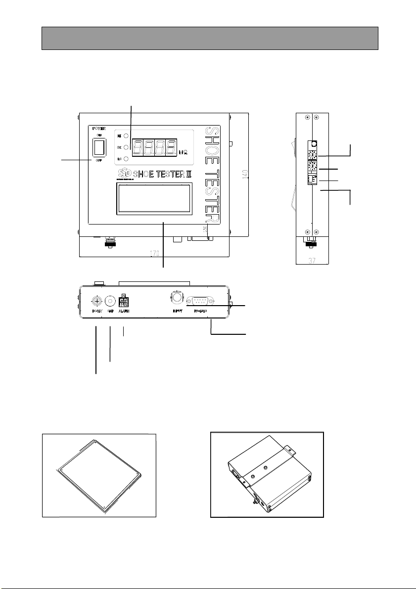
Main Device
Measurement stand Wall mounting rack
Power
switch
Touch button
Self-check
button
O
p
eration settin
g
Power input connector
Insert the dedicated AC adapter here
Earth terminal
Result output terminal
Insert the
result
signal cable here (optional)
Measurement signal connector
Insert the dedicated measurement signal cable
here
RS232C
Measurement result display area
Minimum setting
switch
Minimum setting
switch

EarthLead
■AC adapter
■Dust protection sticker
■Measurement signal cabl
Cautions When Measuring With the Measurement Signal Cable
■ Step onto the measurement stand with your feet together so that your shoes do not
protrude from the stainless steel plate, and then press the touch button.
■ Since the resistance of shoes varies according to the temperature, humidity, and dirt and
friction on the bottom of the shoe, perform periodic measurements and maintenance
management.
■ Note that the resistance value will be higher when thick socks are worn.
■ The measured value may differ if your body is touching a metal plate or other objects
other than the touch button.
■ Do not press the touch button roughly.
Preparation
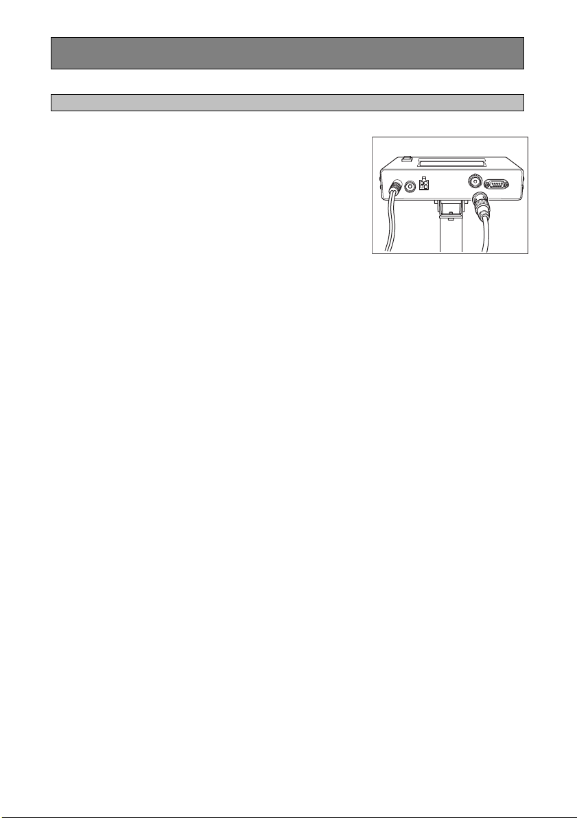
Attaching the Main Device to the Measurement Stand
1.Connect the measurement signal cable
to the bottom of the main device.
Connect the cable to the measurement signa
l
connector on the bottom of the main device.
2.Connect the AC adapter to the power
connector of the main device.
3. Connect the earth lead to the earth
connector and ground it securely.
Insert the earth lead to the earth connector
securely, and connect the clip to a grounding object.
Make sure to ground the earth terminal to ensure
accurate measurements.
Setting and Checking the Device
The following procedure should be performed by the supervisor of the device.
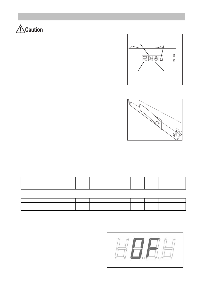
Device Operation Settings
Set the operation setting switches 1 to 4 down for ON
and up for OFF.
The default factory setting is "OFF" for all switches.
1: Buzzer ON (sound) or OFF (silent) for measurement
results that are not OK.
2:Buzzer ON (sound) or OFF (silent) when
measurement is complete.
3: Measure while the touch button is pressed (ON)
10 second measurement mode or 3 second
measurement mode (OFF)
4: 10 second measurement mode (ON)
After changing the settings, attach the included dust
protection sticker.
Setting the Maximum and Minimum Values for Alerts
Set the maximum value and minimum value as the standard for determining the
measurement result.
The factory default setting is "0" (not set) for both switches.
Minimum setting switch
Switch number 0 1 2 3 4 5 6 7 8 9
Setting value
(MΩ) Not set 0.1 0.5 1 5 10 Not set Not set Not set Not set
Maximum setting switch
Switch number 0 1 2 3 4 5 6 7 8 9
Setting value
(MΩ) Not set 1 5 10 20 35 50 100 Not set Not set
All settings are reflected when the device power is turned on. Turn the power off and on
when you have changed a setting.
If the measured value exceeds 200 MΩ,
the following is displayed (overflow).
Operation
setting switches
Minimum setting
switch
Self-check
button
Maximum setting
switch

Checking the Device Operation
If you press the self check button, an internal 1 MΩresistance is measured so the device
can self-diagnose whether it is working properly.
The device is working properly if a measurement between 0.95 and 1.05 MΩis displayed
in the measurement result area.
NOTE
Perform the self check operation when the device has stabilized after turning the power on.

Measuring
1.Turn the power of the main device on.
The power switch lights, and the measurement
display area is off. The area turns on when the touch
button is pressed.
2.While wearing the shoes to measure,
step onto the measurement stand, and
press the touch button in with your
bare hands until you hear a click, and
hold it there for three seconds.
NOTE
Do not touch any objects other than the touch button
while measuring. Doing so will prevent an accurate
measurement.
3.When the value in the measurement result display area
stabilizes, the result is indicated with a light.
If the measured value is within range: OK light (green)
If the measured value exceeds the maximum value: HI light (red)
If the measured value exceeds the minimum value: LOW light (red)
NOTE
If the device is set to make a sound, it will emit an operation complete sound or warning
sound. Refer to "Device Operation Settings" for details.
NOTE
Refer to the following when connecting the optional alarm output cable.
NOTE
The optional RS232C cable can be connected to output measurement data externally.
COM and NO
connection
When power is ON
When result is OK
When power is OFF
When result is not OK
Open Closed
COM and NC
connection
When power is ON
When result is OK
When power is OFF
When result is not OK
Closed Open

4.When measurement is complete, turn the power switch off.
Adjustment and Maintenance
Clean the measurement stand periodically.
Troubleshooting
If the device does not operate correctly, it may be the result of one of the following.
■ The screen is not displayed after switching the power on.
Cause: The AC adapter is broken.
Remedy: Check whether the AC adapter is outputting DC 12 V.
■ An overflow is displayed when the touch button is pressed.
Cause: The connector is disconnected.
Remedy: Check whether the connector is disconnected from the measurement stand or touch
button.
Directly connect the measurement stand and touch button and check whether a value
between 0.00 and 0.02 is displayed.
Specifications
Weight: main device 0.9 kg
: with supports and
angle adjustment
1.2 kg
: measurement stand 4.5 kg
Measurement voltage DC 10 V
Function check 1 MΩ
Measurement range 0.00 to 200 MΩ
Power supply DC 12 V AC adapter (AC 100 to 240 V)
Measurement precision ±10% + 2 digits
Maximum setting 1, 5, 10, 20, 35, 50, 100 (MΩ)
Minimum setting 0.1, 0.5, 1, 5, 10 (MΩ)

Warranty Valid for: 1 year after delivery
Product
name SHOE TESTER II
Model Serial
number
Date of
Delivery Inspection
Stamp
1. If any malfunctions or damage occur to the product due to any of the following reasons, a
charge will be incurred for repairing or replacing the product.
2. Malfunctions or damage occurring to the product due to misuse or improper storage.
・ Malfunctions or damage occurring to the product due to repairs or modifications
conducted by a party other than SHISHIDO ELECTROSTATIC or a company specified
by SHISHIDO ELECTROSTATIC.
・ Malfunctions or damage occurring to the product due to fire, natural disasters, or other
acts of providence.
・ Other malfunctions or damage occurring to the product deemed not to be the
responsibility of SHISHIDO ELECTROSTATIC.
For any queries relating to the product, contact the sales office where you purchased the
product.
SHISHIDO ELECTROSTATIC, LTD. http://www.shishido-esd.co.jp/
HEAD OFFICE MARUNOUCHI BLDG. 9F-918, 4-1, MARUNOUCHI 2-CHOME,
CHIYODA-KU, TOKYO, 100-6309
SALES DEPARTMENT TOKYO
BRANCH EXPORT DIVISION
3-3, HIGASHI-YUKIGAYA 1-CHOME,
OTA-KU, TOKYO, 145-0065
TEL: +81-3-3727-0161 FAX: +81-3-3727-0342
OSAKA BRANCH
OSAKA ORUGAN BLDG. 2F-203, 4-2,
TANIMACHI 1-CHOME, CHUO-KU,
OSAKA, 540-0012
TEL: +81-6-6949-3712 FAX: +81-6-6949-3707
NAGOYA BRANCH
RAINBOW TSURUMAI 6F, 1-2,
TSURUMAI 2-CHOME, SHOWA-KU,
NAGOYA, AICHI-PREF, 466-0064
TEL: +81-52-884-5565 FAX: +81-52-883-3077
FUKUOKA BRANCH
DAI10 UEMURA BLDG. 8F-A, 6-4,
TAKASAGO 2-CHOME, CHUO-KU,
FUKUOKA, FUKUOKA-PREF, 810-0011
TEL: +81-92-531-7485 FAX: +81-92-526-7326
SENDAI BRANCH
KIMACHI HOME PLAZA 101,
5-26, KASHIWAGI 1-CHOME, AOBA-KU,
SENDAI, MIYAGI-PREF, 981-0933
TEL: +81-22-271-6231 FAX: +81-22-271-6232
01-’12
Table of contents
Other SSD Measuring Instrument manuals


Popular Measuring Instrument manuals by other brands


King Instrument
King Instrument 7200 Series installation instructions

Milwaukee
Milwaukee MI404 user manual

Xylem
Xylem WTW Turb 430 IR/T operating manual

ero electronic
ero electronic DPS instruction manual

PRECISION DIGITAL
PRECISION DIGITAL PD213 operating instructions

HEIDENHAIN
HEIDENHAIN MSE 1202 installation instructions


