SSI PRL-1600 User manual

PRL-1600
Wireless Pulse Link
System Technical
Manual
Solid State Instruments
A division of Brayden Automation Corporation
6230 Aviation Circle
Loveland, CO, USA 80538
(970)461-9600
e-mail: support@brayden.com
Revision: A1
Date: 4/10/2022

PRL-1600 Wireless Pulse Link System
Table of Contents
Solid State Instruments
A division of Brayden Automation Corporation
6230 Aviation Circle
Loveland, CO, USA 80538
(970)461-9600
e-mail: support@brayden.com
Introduction . . . . . . . . . . . . . . . . . . . . . . . . . . . . . . . . . . . . . . . . . . . . . .
PRNT-1600 Pulse Radio Transmitter . . . . . . . . . . . . . . . . . . . . . . . . .
PRT-16 Transmitter Base Unit . . . . . . . . . . . . . . . . . . . . . . . . . . . . . .
Using the 2-Wire (Form A) or 3-Wire (Form C) Modes . . . . . . . . . . . . .
PRNR-1600 Pulse Radio Receiver . . . . . . . . . . . . . . . . . . . . . . . . . .
PRR-16 Receiver Base Unit . . . . . . . . . . . . . . . . . . . . . . . . . . . . . . . .
Troubleshooting and Tech Support . . . . . . . . . . . . . . . . . . . . . . . . . . . .
Pulse Link System Design and Planning . . . . . . . . . . . . . . . . . . . . . . . .
Considerations for a Successful Installation . . . . . . . . . . . . . . . . . . . . .
4
23
19
16
13
11
9
6
5
FCC/IC Notices . . . . . . . . . . . . . . . . . . . . . . . . . . . . . . . . . . . . . . . . . . .
3
17Transmitter and Receiver Pairing Procedure . . . . . . . . . . . . . . . . . . . . .
System Diagram . . . . . . . . . . . . . . . . . . . . . . . . . . . . . . . . . . . . . . . . . . 18
Appendix . . . . . . . . . . . . . . . . . . . . .. . . . . . . . . . . . . . . . . . . . . . . . . . . . 21

Introduction
The PRL-1600 Pulse Radio Link is a Transmitter and Receiver system that wirelessly sends up to four channels of KYZ
pulses from the transmitter to a paired receiver. The short-hop PRL-1600 has a range of up to 5,000 feet depending on
site topography and solves the problem of getting pulses across parking lots, vacant lots, roads, railroad tracks or other
obstacles. With the PRL-1600, you're now able to connect real-time KYZ pulses from 2 Form C pulse channels or 4
Form A pulse channels. Pulses from each meter output are independently outputted on one of the four channels in the
receiver. The PRL-1600 eliminates trenching or other costly methods of getting wires strung between each meter and
the destination device as well as providing superior isolation against transients that could be induced in a long cable run.
Additionally, ground rise problems are eliminated since there is no electrical connection between the two devices.
The PRL-1600 Radio Pulse Link system consists of one PRT-1600 Transmitter and one PRR-1600 Receiver. The
system uses Frequency Hopping Spread Spectrum (FHSS) technology to communicate on 64 frequencies between 902
to 927MHz, using one of 6 hop sequence "channels", and allows unlicensed operation by the user, allowing multiple
systems to operate in the same radio airspace. Nominally, the PRL-1600 will transmit pulses between 2,500 and 5,000
feet in an unobstructed line-of-sight configuration but may go farther depending on optimal site conditions.
PRT-1600 TRANSMITTER
The PRT-1600 Transmitter consists of the following:
*PRNT-1600 Pulse Radio Transmitter/Antenna Unit
*PRT-16 Pulse Transmitter Base Unit
The PRT-1600 Transmitter receives pulses from a meter's KYZ pulse initiator and sends them to the PRR-1600
Receiver unit wirelessly. Each 10 second interval, the number of pulses received from the meter's pulse KYZ initiator, is
transmitted to the Receiver upon the next transmission cycle. The Receiver will then generate the correct number of
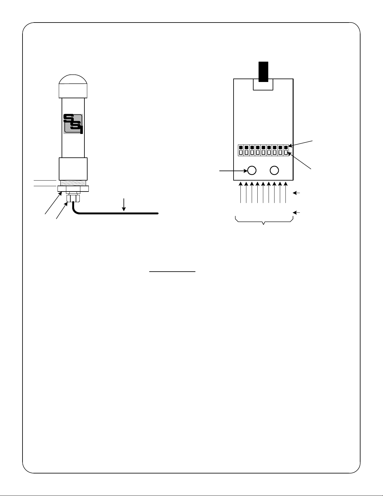
pulses at KYZ outputs, over the next 10 seconds. The PRNT-1600 Transmitter/Antenna Unit contains the transceiver
radio, a microcontroller and all the circuitry and software to communicate with the Receiver. The PRT-16 Base Unit
contains the power supply, termination points, and has a built-in low voltage transformer-isolated power supply
generating a +13VDC sense (wetting) voltage. The sense voltage is connected to meter's dry-contact KYZ pulse initiator.
The PRT-1600 Transmitter is capable of operating on supply voltages of 120 or 208-277VAC. In addition to line power, it
can be operated with batteries or a solar power supply such as Solid State Instruments' SPS-1 Solar Power Supply by
using the PRT-16S 12VDC Transmitter Base Unit.
PRR-1600 RECEIVER
The PRR-1600 Receiver consists of the following:
*PRNR-1600 Pulse Radio Receiver/Antenna Unit
*PRR-16 Pulse Receiver Base Unit
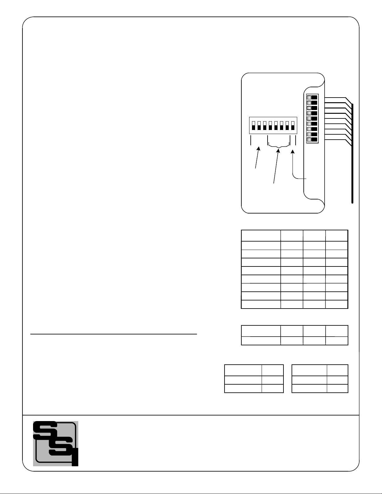
The PRR-1600 contains the transceiver radio, a microcontroller and all the circuitry and software to receive pulses from
the Transmitter and output them on one of four output channels. The PRR-12 Base Unit contains the power supply,
output relays and termination points where all connections are made. Four output channels are available, and can be
configured as 4 Form A or 2 Form C. Each output channel contains one KY Form A (2-Wire) Solid State output. The
Receiver/Antenna unit is intended to be mounted outdoors, in a direct line-of-sight with the Transmitter/Antenna units. It
cannot operate if obstructed by trees, metal poles, buildings or other objects. The Receiver Base Unit is designed to
mount indoors, or inside an existing control enclosure suitable for the application. The Base and Radio/Antenna Units
are connected together by means of an 8-conductor, #24AWG 4 twisted pair shielded control cable. It is important for
noise immunity and error-free communications between the Base and Transceiver that 4-twisted pair shielded control
cable be used. The PRR-1600 is capable of operating on supply voltages of 120VAC or 208-277VAC. Other power
supply voltages are available upon special order.
3

SOLID STATE INSTRUMENTS
PRL-1600 SYSTEM DESIGN AND
PLANNING
Revision: 4/10/22
SYSTEM CONFIGURATION - The PRL-1600 can be used in one of two configurations: 4 Form A pulse
channels or 2 Form C pulse channels. The entire system operates in either one mode or the other. They cannot
be mixed.
Form A Configuration: The Form A configuration will transmit four 2-Wire (KY) pulse channels.
Form C Configuration: The Form C configuration will transmit two 3-wire (KYZ) pulse channels.
Determine the desired mode for the system.
Dip Switch DS1's switches #1 through #3 set the channel # or "hop" sequence. Both the PRT Transmitter and
the PRR Receiver units must be set to the same channel or hop sequence. See Table 1 at left.
a division of Brayden Automation Corp.
6230 Aviation Circle, Loveland, Colorado 80538
Phone: (970)461-9600
E-mail:support@brayden.com
4
23456781
4
CHAN#
2
1
Dip Switch DS1
SYSTEM CHANNEL - The PRL-1600 System operates on one of 6 hop sequence channels. Each channel
consists of 50 unique frequencies out of 64 frequencies available in the 902MHz to 927MHz range. This allows
great reliability since RF transmissions are transmitted on one of the channel frequencies until they are received
by the receiver. Set the Transmitter and the Receiver to the same channel number. Multiple PRL-1600 systems
can operate in the same radio airspace by each system having a different channel number. Once you have
determined the channel # that you will use, configure Dip Switch S1's switches #1 through #3 on the PRT-16 or
16S Transmitter Base board and the PRT-16 Receiver Base board. Table 1 shows the dip switch combinations
for each channel.
Channel # DS1.1 DS1.2 DS1.3
6
6
6
5
4
3
2
1DN DN DN
DN DN UP
DN UP DN
DN UP UP
UP DN DN
UP DN UP
UP UP DN
UP UP UP
Learn
Table 1
PRT-16 and
PRR-16 Base
Boards
Set XMTR
channel # on
PRT-16 or
PRR-16
Learn Mode Enable
SYSTEM OPERATING MODE - The PRL-1600 System operates in a near real-time operational mode, where
the PRT-1600 Transmitter transmits one transmission every 10 seconds with the pulse data it has received from
the meter over the previous 10-second period. When the transmission is received by the PRR-1600 Receiver,
pulses are generated over the next 10-second period. Additional error checking and pulse verification are used
in this mode for the highest possible accuracy. Packet Transmissions and Receptions are visually indicated
with an LED on both base units.
Dip Switches #4 thru
#7 are specific to the
Transmitter or
Receiver.

SOLID STATE INSTRUMENTS
CONSIDERATIONS FOR A
SUCCESSFUL INSTALLATION
Revision: 4/10/22
GENERAL - The PRL-1600 System is designed to provide mirror-image pulses from the transmitter to the
receiver. This is important for Peak Demand Control since the KW demand is determined by timing the pulses.
The greater the time between pulses, the lower the demand. Conversely, the shorter time between pulses, the
higher the demand. Every effort is made in the PRL-1600 to be a "virtual copper wire" and make the pulses
coming out of the receiver the same pulse width as the pulses going into the transmitter.
The PRL-1600 System is designed for concentrated RF environments where there is a significant amount of RF
traffic on these or adjacent frequencies. Pulses are collected by the transmitter for 10 seconds. The number of
pulses received in the immediate 10-second period is then sent to the receiver which duplicates those pulses over
the next 10 seconds. All output pulses are thus delayed by 10 seconds. The benefit of this method is significantly
reduced RF traffic and high-accuracy due to the expanded error checking and pulse count "true up".
APPROPRIATE PULSE CONSTANT - It is important to properly program the Pulse Constant of the meter such
that there are no more than 2 pulses per second at the peak KW demand of the building or facility. Pulses faster
than this may be lost. If a high pulse rate is unavoidable from the meter and cannot be slowed down, consider one
of the DPR Dividing Pulse Relays from Solid State Instruments.
MINIMUM PULSE WIDTH - Make sure that the pulse width coming from the meter is at least 100mS in duration.
LINE OF SIGHT - Make sure that you have the Receiver Radio/Antenna Unit in a location where the Transmitter's
Radio/Antenna unit can "see" it with a wide field of view. The PRL-1600 is a Line-Of-Sight system, and the
transmitter must have uninterrupted and unrestricted sight with the receiver radio at all times. Make sure that
there are no trees, metal buildings, light poles, rail cars, trucks, buses or any other obstruction that gets in the line-
of-sight between the transmitter and receiver at any time. Interruptions in the line-of-sight may cause pulses to be
lost. Generally speaking, the PRL-1600 will not transmit through concrete, concrete block or masonry walls. We
can't stress this enough: The RF path must be line of sight!
HEIGHT - Mount the Transmitter and Receiver Radio/Antenna units up off the ground as high as reasonably
possible, 14' minimum, to eliminate RF reflections, improve reception and transmission distance. The higher the
transmitter is off the ground, the longer the transmission distance and the more reliable the reception by the
receiver.
MOUNTING: If mounting the Receiver Radio/Antenna unit on the side of a metal building, make sure that the
antenna in the Radio/Antenna unit is mounted at least 6.1" away from the metal siding. Use the brackets supplied
with the PRL-1600 to get this distance. You may have to rotate the board to insure that the antenna is not closer
to the metal surface than 6.1", since the antenna is not exactly in the center of the board as well as the board
being mounted in an off-set fashion. If the antenna is closer than 6.1", the signal may be corrupted and
transmissions may be affected. Rotate each radio/antenna units' board if possible so the board is perpendicular to
the transmtter or receiver on the opposite end of the system, keeping the antenna 6.1" away from any metal.
INTERFERENCE - The PRL-1600 is a Frequency-Hopping Spread Spectrum system the communicates on 50 of
the 64 frequencies. It may or may not work in substations or in other areas where there is high-power energy
fields exist or where RF energy may jam the signal. The electromagnetic field around high voltage conductors
may cause enough interference so as to keep the system from transmitting correctly or may significantly reduce
the range of the system. It has been reported that other high-power RF transmitters mounted within close proximity
can jam the signal even though they are not using the same frequencies.
a division of Brayden Automation Corp.
6230 Aviation Circle, Loveland, Colorado 80538
Phone: (970)461-9600
E-mail:support@solidstateinstruments.com
5

INSTRUCTION SHEET
PRNT-1600 PULSE RADIO TRANSMITTER
MOUNTING POSITION - (See Note Below on Cable Connection before mounting) The PRNT-1600 Transmitter/
Antenna unit should be mounted in an upright position so that the cable is located on the bottom of the unit. Mount
the unit as high as necessary to guarantee LINE-OF-SIGHT with the PRNR-1600 Receiver/Antenna unit. Mount
using the aluminum mounting bracket supplied, making sure that the center of the transmitter is at least 6.1" away
from any metal object such as a pole or metal building. Make sure that no metal mounting hardware is placed
above the bottom of the PRNT-1600 Transmitter/Antenna unit case.
CABLE CONNECTION TO PRNT-1600 - It is advisable that this task is performed, if possible, in a convenient, clean
work area before mounting the Transmitter unit. Connect the 4-twisted pair 24AWG(min) shielded control cable to
the 9-position connector on the PRNT-1600 Board. Access the PCB Assembly by unscrewing the Transmitter
housing cap on the bottom of the unit. Remove the Transmitter assembly from the housing. Feed the control cable
into the housing's weather-tight connector on the cap so that there is approximately 12" of cable through the cap.
Tighten the weather-tight cable fitting so that the cable is not quite tight and easily slides back and forth. Alternately,
non-metalic conduit ("Seal-Tight" or "Carflex") may be used to connect directly to the housing and run the control
cable to the Base unit inside this conduit.
Strip approximately 2" of the control cable's outer jacket to expose the individual conductors, being careful not to cut
the insulation of the conductors or any strands of the shield's drain wire. Strip the insulation of each conductor back
1/4". Connect each conductor of the cable to the 9-position connector TB1 using a small flat-blade screwdriver or
other similar tool to open the spring-loaded connector as shown above in Figure 2. Press down on connector lever,
slip wire into hole and release. When all conductors are attached, attach a cable tie (ty-rap) through the Transmitter
PCB Assembly's holes and tighten the control cable down, leaving about 1/4" of jacket above the ty-rap so as to
provide adequate strain relief for the cable connections. Pull the cable back through the cap and weather-tight
connector and place the Transmitter PCB Assembly back into the cap's slots. Tighten the weather-tight connector to
secure the assembly in place. Put the ring spacer over the Cap's threads and insert the Transmitter Assembly into the
housing. Tighten the cap until spacer is tight. For best results, keep the length between the Transmitter and the Base
Unit to the minimum practical distance. When Transmitter installation is complete, secure cap to mounting bracket
using sheet metal screw in slot.
Revision: 4/10/22
To PRT-16 Transceiver Base Unit
123456789
SCK-
SDI+
SDI-
SCK+
+V
GND
BR/O
BRN
OR/W
ORG
GR/W
GRN
BL/O
BLU
SHLD SLVR
SDO+
SDO-
TB1
8-Conductor 24AWG(min) Control
Cable with shield -100' max.
To Transmitter
Base Unit
Ty-Rap holes
for Cable
Strain Relief
Transmitter/
Antenna PCB
Assembly (Tx)
Cap
Weather-tight
Strain Relief
FIGURE 1 FIGURE 2
FCC ID: TIT-PRT-1600
Spring-loaded
Lever (Press
down to open)
Insert wire
here and
release lever
6
Wire
Function
Wire
Color
PRNT-1600
Transmitter/
Antenna Unit
PRNT-1600
Transmitter/
Antenna
Board
Ring Spacer

INSTRUCTION SHEET
PRT-1600 PULSE RADIO TRANSMITTER
(con't)
RADIO OUTPUT - The PRT-1600's Transceiver/Antenna Unit(PRNT-1600) contains a 900MHz band FHSS
radio transceiver with an integral antenna mounted inside the unit. See diagram for mounting method and
considerations. Transmission is LINE OF SIGHT up to approximately 5,000 feet max. Metal poles, buildings or
other objects will affect the distance the radio system will effectively work. Trees may also affect transmission
distance. The user bears all responsibility for proper mounting and operation of the unit within the PRT-1600's
operating parameters.
Revision: 4/10/22
PRT-16
Transmitter
Base Unit
(Not to Scale)
8-Conductor (4-Twisted Pairs)
24AWG Control Cable with
shield -100' max.
POWER INPUT - The PRNT-1600 receives its power supply from the PRT-16 Transmitter Base unit.
NOTICE TO USER -
FCC ID: TIT-PRT-1600
This device complies with Part 15 of the FCC Rules. Operation is subject to the following two conditions:
1. This device may not cause harmful interference; and
2. This device must accept any interference received including interference that may cause undesired operation.
1
2
3
4
5
6
7
8
9
METER INPUTS - See the PRT-16 Base Unit Instruction Sheet for detailed information on connecting the K-Y
pulse inputs to the Electric Meter's KYZ Pulse output.
7
TRANSMITTER CHANNEL - Set the channel number (hop sequence) using DIP Switches #1 through #3 ON
DS1 as shown in Table 1 on page 4. This is set on the PRT-16 Transmitter Base Board.
PRNT-1600
Transmitter/
Antenna Unit
DS1

SOLID STATE INSTRUMENTS
INSTRUCTION SHEET
PRNT-1600 RADIO/ANTENNA UNIT WIRING
a division of Brayden Automation Corp.
6230 Aviation Circle, Loveland, Colorado 80538
Phone: (970)461-9600
E-mail: support@brayden.com
Revision: 4/10/22 8
123456789
TB1
Transmitter/
Antenna PCB
Assembly
LED1
PRNT-1600
Wire Connection Assignments
1
3
2
4
6
5
7
8
9
Terminal # Pair #
1B
2A
2B
3A
3B
1A
4A
4B
-
ORG/WHT
ORG
GRN/WHT
BLU/WHT
BLU
GRN
BRN/WHT
SILVER
BRN
BRN
Color Size (AWG)
24
24
24
24
24
24
24
24
24
Function
GROUND
SCK+
SCK-
SDI+
SDI-
VIN
SDO+
SHIELD
SDO-
1
6
2
5
3
4
8
9
7
CONTROL
CABLE TO
BASE UNIT
ORG
ORG/WHT
GRN
BLU
BLU/WHT
GRN/WHT
PAIR#1
SILVER
BRN/WHT
PAIR#2
PAIR#3
PAIR#4

SOLID STATE INSTRUMENTS
INSTRUCTION SHEET
PRT-16 BASE UNIT
Setting the System CHANNEL - Each system -- the Transmitter and
Receiver -- must operate on one of six different channels. A
"channel" is a collection of 50 specific frequencies that are arranged
in a specific "hop sequence". A unique channel allows multiple
systems to operate in the same radio airspace without any
interference with each other. Therefore, the transmitter and receiver
must have the same channel setting. The channel address is set
using a 3-bit binary code. See Table 1 at right for complete list of the
channels. Note that Channel #6 is the highest channel number and
even though there are eight unique switch combinations, Channel 6 is
the highest channel that can be selected. The last three switch
combinations all result in Channel #6 being selected.
Switch #4 - Not used.
Switch #5 - Not used.
Switch #6 - Not used
Switch #7 - Setting the Transmitter Input Mode - The PRL-1600
can operate in the Form C or Form A modes. In the Form C (3-Wire)
mode, each input channel uses the K, Y and Z inputs. Two
independent 3-Wire meter pulse channels can be transmitted. In the
Form A (2-Wire) mode, each pulse channel uses the K (common)
and a Y input. Four independent 2-Wire meter pulse channels can
be transmitted. Set Switch #7 to the DOWN position for the Form A
mode and UP for Form C mode.
Switch #8 - Pairing the Transmitter and Receiver - The PRT-1600
System requires that each Transmitter and Receiver are paired
together. Each Transmitter must learn the address of the Receiver it
is designated to talk to. This makes it possible for the Transmitter to
only talk to the designated Receiver and ignore other devices sending
and receiving information on a particular frequency. After installation
is complete, perform the pairing procedure described on page 15
ONLY IF the system has not been previously paired at the factory.
***Do not switch #8 UP if the system is already paired.***
a division of Brayden Automation Corp.
6230 Aviation Circle, Loveland, Colorado 80538
Phone: (970)461-9600
E-mail: support@brayden.com
Revision: 4/10/22 9
CHANNEL#
1
2
3
4
5
6
6
6
DN
DN
DN
DN
UP
DN
TABLE 1
SW#1 SW#2 SW#3
DN
DN
UP
DN
UP
UP
DN
UP
DN
UP UPDN
UP DNUP
UP UPUP
Input Mode
DN
UP
TABLE 2
SW#7
FORM C (3W)
FORM A (2W)
Mode
DN DN
SW#4 SW#5 SW#6
DNDEFAULT
TABLE 3
Run/Learn
DN
UP
SW#8
LEARN
RUN
TABLE 4
PRT-16
Transmitter
Base Unit
1
2
3
4
5
6
7
8
9
23456781
4
CHAN#
2
1
Dip Switch DS1
Learn
Set XMTR
channel #
Dip Switches #4 - #7
are specific to the
Transmitter. See
below.
Learn
Mode
Enable
CONTROL CABLE

SOLID STATE INSTRUMENTS
INSTRUCTION SHEET
PRT-16 PULSE TRANSMITTER BASE
GND
Y2
Y1
K
NEU
120V
Input #1
POWER SUPPLY
INPUT
MOUNTING POSITION - The PRT-16 Base unit may be mounted in any position.
POWER INPUT - For 120VAC, connect the "hot" lead to the L1 power supply terminal. Connect the neutral lead
to the NEU terminal. For a power supply voltage between 208 and 277 VAC, connect the "hot" lead to the L2
power supply terminal and the neutral lead to the NEU terminal. Use EITHER L1 or L2 for the appropriate
voltage input but not both. Connect the GND terminal to Ground.
METER CONNECTIONS - Form A (2W) mode: Connect the PRT-12's "K" and "Y1" input terminals to meter's
"K" and "Y" terminals. The "Yx" input terminals are "pulled-up" to +13VDC power supply, making it compatible
with open-collector transistor meter outputs, as well as all non-polarized mechanical or solid state pulse outputs.
Form C (3W) mode: Connect the PRT-16's "K", the "Y1" and the "Z1" input terminals to the meter's "K", "Y" and
"Z" terminals. The PRT-16's "K" terminal is the system common (return).
Common return from meter
277V
Revision: 4/10/22
To PRNT-1600
Transmitter Radio/
Antenna Unit
L2
L1
N
G
Kin
Y1in
Z1in
INPUT CONFIGURATION - The PRT-16 accepts either 2 Form "C" (3-Wire) inputs using the K, Y & Z input
terminals, or 4 Form "A" (2-Wire) inputs using the K & Y and K & Z terminals. See Dip Switch Definitions and
Settings.
Y4
Y3
Y2in
Z2in
SCK-
SDI+
SDI-
SCK+
+V
GND
24AWG (min)/8-conductor (4-twisted pairs)
with shield 100' max. See Page 8.
OUTPUT TO PRNT-1600 TRANSMITTER/ANTENNA UNIT - Connect the 8-conductor (4-TWISTED PAIRS)
24AWG(min) shielded control cable to the PRNT-1600 Transmitter/Antenna Unit. For best results, it is advisable
to keep this length of this cable to the minimum practical distance.
BR/W
OR/W
BRN
ORG
GR/W
GRN
BL/W
BLU
1
2
3
4
5
6
7
SHLD SVR
8
9
SDO+
SDO-
TB2
TB1
a division of Brayden Automation Corp.
6230 Aviation Circle, Loveland, Colorado 80538
Phone: (970)461-9600
E-mail: support@brayden.com
ENCLOSURE - The PRT-16 base unit is housed in a polycarbonate base and cover and is designed to be
mounted into another electrical enclosure suitable for the application. Optional NEMA 3R or NEMA 4X outdoor
enclosures are available.
Wire
Function
Wire
Color
10
Input #2
Input #3
Input #4
2 Meters'
KYZ (3W)
outputs
KZ
KY
K
Z
KY
3W 2W
4 Meters'
KY (2W)
outputs
KY
KY
KY
KY

SOLID STATE INSTRUMENTS
a division of Brayden Automation Corp.
6230 Aviation Circle, Loveland, CO 80538
Phone: (970)461-9600
E-mail:support@brayden.com
INSTRUCTION SHEET
PRNR-1600 PULSE RADIO RECEIVER
MOUNTING POSITION - (See Note Below on Cable Connection before mounting) The PRNR-1600 Receiver/Antenna unit
should be mounted in an upright position so that the cable is located on the bottom of the unit. Mount the unit as high as
necessary (14' min.) to guarantee LINE-OF-SIGHT with the PRNT-1600 Transmitter/Antenna unit. Mount using the aluminum
mounting bracket supplied, making sure that the antenna of the receiver is at least 6.1" away from any metal object such as a
pole or metal building. Make sure that no metal mounting hardware is placed above the bottom of the receiver unit case.
CABLE CONNECTION TO PRNR-1600 - Perform this task in a convenient, clean work area before mounting the Receiver unit.
Connect the 8-conductor (4-twisted pairs) shielded control cable to the 9-position connector on the PRNR-1600 PCBA. (See
page 14) Access the PCB Assembly by unscrewing the housing cap on the bottom of the unit. Remove the board assembly from
the housing. Feed the control cable into the housing's weather-tight connector on the cap so that there is approximately 12" of
cable through the cap. Tighten weather-tight cable fitting so that the cable is not quite tight and easily slides back and forth.
Strip approximately 2" of the control cable's outer jacket to expose the individual conductors, being careful not to cut the
insulation of the conductors or any strands of the shield's drain wire. Strip the insulation of each conductor back 1/4". Connect
each conductor of the cable to the 9-position connector TB1 using a small flat-blade screwdriver or other similar tool to open the
spring-loaded connector as shown above in Figure 2. Press down on the connector lever, slip wire into hole and release. When
all conductors are attached, attach the cable tie(ty-rap) included through the PCBA's holes and tighten the control cable down,
leaving about 1/4" of jacket above the ty-rap so as to provide adequate strain relief for the cable connections. Pull the cable back
through the cap and weather-tight connector and place the PCB Assembly back into the cap's slots. Tighten the weather-tight
connector (cable gland, if used) to secure the assembly in place. Rotate the board until it is perpendicular with the transmitter,
making sure that the Antenna is 6.1" away from any metalic mounting surface. Put the ring spacer over the Cap's threads and
tighten the cap until spacer is finger tight. For best results, keep the distance between the Receiver and the Base Unit to the
minimum practical distance. When PCBA installation is complete, secure cap to mounting bracket using sheet metal screw in
slot.
Revision: 4/10/22
To Receiver Base Unit
123456789
SILVER
TB1
8-Conductor Shielded Control
Cable -100' max.
To Receiver
Base Unit
Ty-Rap holes
for Cable
Strain Relief
PRNR-1600
Receiver/ Antenna
PCB Assembly
Cap
Weather-tight
Strain Relief
FIGURE 1 FIGURE 2
Spring-loaded
Lever (Press
down to open)
Insert wire
here and
release lever
11
Wire
Function
Wire
Color
SCK-
SDI+
SDI-
SCK+
+V
GND
BR/W
BRN
OR/W
ORG
GR/W
GRN
BL/W
BLU
SHLD
SDO+
SDO-
Ring Spacer
PRNR-1600
Receiver/
Antenna Unit

INSTRUCTION SHEET
PRR-1600 PULSE RADIO RECEIVER
(con't)
RADIO RF INPUT - The PRNR-1600's Receiver/Antenna Unit contains a low-power 900MHz radio transceiver
with an integral antenna mounted inside the unit. Observe the following application guidelines: 1.) Mount the
transceiver as directed on the reverse side of this sheet; 2.) Locate the PRNR-1600 Receiver/Antenna unit so it
is LINE-OF-SIGHT with the transmitter of the system; 3.) Ensure that all metal objects, trees and other
obstructions, which may affect the distance the radio system will effectively work, are not within the line-of-sight
between the transmitter and receiver.
Revision: 4/10/22
PRR-16
Receiver
Base Unit
(Not to Scale)
8 conductor (4-twisted pair)
#24AWG shielded Control
Cable -100' max.
POWER INPUT - The PRNR-1600 receives its power supply from the PRR-16 Receiver Base unit.
NOTICE TO USER - This equipment has been tested and found to comply with the limits for a class B digital
device, pursuant to part 15 of the FCC Rules. These limits are designed to provide reasonable protection against
harmful interference in a residential installation. This equipment generates, uses and can radiate radio frequency
energy and if not installed and used in accordance with the instructions, may cause harmful interference to radio
communications. However, there is no guarantee that interference will not occur in a particular installation. If this
equipment does cause harmful interference to radio or television reception, which can be determined by turning
the equipment off and on, the user is encouraged to try to correct the interference by one or more of the
following measures:
* Reorient or relocate the receiving antenna.
* Increase the separation between the equipment and receiver.
* Connect the equipment into an outlet on a circuit different from that to which the receiver is connected.
* Consult the dealer or an experienced radio/TV technician for help.
In order to maintain compliance with FCC regulations, shielded cables must be used with this equipment.
Operation with non-approved equipment or unshielded cables is likely to result in interference to radio and TV
reception. The user is cautioned that changes and modifications made to the equipment without the approval of
manufacturer could void the user's authority to operate this equipment.
1
2
3
4
5
6
7
8
9
PULSE OUTPUTS - See the PRR-16 Base Unit Instruction Sheet for detailed information on connecting the KYZ
Outputs to the receiving device. The receiving (destination) device may be the input to an energy management
system, recorder, SCADA system, RTU, or other device configured to receive pulses.
12
PRNR-1600
Receiver/
Antenna Unit
Dip Switch DS1
23456781
4
CHAN
2
1
RSSI
R/L

SOLID STATE INSTRUMENTS
INSTRUCTION SHEET
PRR-16 BASE UNIT
a division of Brayden Automation Corp.
6230 Aviation Circle, Loveland, Colorado 80538
Phone: (970)461-9600
E-mail: support@brayden.com
Revision: 4/10/22 13
CHANNEL#
1
2
3
4
5
6
6
6
DN
DN
DN
DN
UP
DN
TABLE 1
SW#1 SW#2 SW#3
DN
DN
UP
DN
UP
UP
DN
UP
DN
UP UPDN
UP DNUP
UP UPUP
Setting the System CHANNEL - Each system -- the Transmitter and
Receiver -- must operate on one of six different channels. A "channel"
is a collection of 50 specific frequencies that are arranged in a specific
"hop sequence". A unique channel allows multiple systems to operate
in the same radio airspace without any interference with each other.
Therefore, the transmitter and receiver must have the same channel
setting. The channel address is set as a 3-bit binary code. See Table 1
at right for complete list of the channels. Note that Channel #6 is the
highest channel number and even though there are eight unique switch
combinations, Channel 6 is the highest channel that can be selected.
The last three switch combinations all result in Channel #6 being
selected.
Switch #4 - Not used.
Switch #5 - Fixed Pulse Width. Sets the output pulse width to 50mS
(DOWN) or 100mS (UP) when in Form A mode.
Switch #6 - Not used.
RSSI Indicator* - The receiver has an Signal Strength Indicator to
show the signal strength of the Transmitter. This is a test mode and
can only be used during installation. See Diagnostics on page 18.
Once the system is operational, set Switch #7 to DOWN to turn off the
RSSI.
Pairing the Transmitter and Receiver - The PRL-1600 System
requires that each Transmitter and Receiver are paired together. Each
Transmitter must learn the address of the Receiver it is designated to
talk to. This makes it possible for the Transmitter to only talk to the
designated Receiver and ignore other devices sending and receiving
information on a particular frequency. After installation is complete
perform the Pairing Procedure described on page 16 ONLY if the
pairing procedure has NOT been done at the factory. ***Do not put
switch #8 into the UP position if the system has already been
paired.***
RSSI Mode
DN
UP
TABLE 2
SW#7*
RSSI Enable
RSSI Disable
Mode
DN
SW#4 SW#6
DNDEFAULT
TABLE 4
Run/Learn
DN
UP
SW#8
LEARN
RUN
TABLE 5
PRR-16
Receiver
Base Unit
(Not to Scale)
1
2
3
4
5
6
7
8
9
Dip Switch DS1
23456781
4
CHAN
2
1
RSSI
R/L
DN
UP
SW#5
100 mS
50 mS
TABLE 3
Pulse Width

SOLID STATE INSTRUMENTS
INSTRUCTION SHEET
PRR-16 PULSE RECEIVER BASE UNIT
Revision: 4/3/22
OUTPUT CONFIGURATION - The PRR-16 contains four solid state Form A dry-contact outputs, two each for
both "K", "Y" and "Z" outputs. Each solid state output is limited to 100mA@ 250VAC, 800mW maximum. Fuses
are sized at 1/10th amp (100mA). Do not exceed this rating as the device will be destroyed. Transient voltage
protection for the contacts of the solid state relays are provided by MOVs on board.
a division of Brayden Automation Corp.
6230 Aviation Circle, Loveland, Colorado 80538
Phone: (970)461-9600
E-mail:support@brayden.com
RSSI SIGNAL STRENGTH INDICATOR - The PRR-16 contains a 3-LED bar graph that tells the relative signal
strength coming from the Transmitter. It consists of three RED LEDs in the upper left-hand corner of the board.
14
GND
K
Y
Z
NEU
120V
OUTPUT #1
POWER SUPPLY
INPUT
STATUS LEDS - The PRR-16 has four status LEDs to indicate the status of the system at all times. See Page
__ for description of the Status LED functions.
POWER INPUT - For a power supply of 120 VAC, use the the L1 terminal for the "hot" lead. For 208 to 277
volts AC, use the L2 terminal for the "hot" lead. Connect the Neutral lead to the NEU terminal. Connect the GND
terminal to Ground. GROUND MUST BE CONNECTED TO A GOOD ELECTRICAL SYSTEM GROUND!!!
SIGNAL INPUT - The PRNR-1600 receiver/antenna unit connects to the 9-position connector labelled TB2.
Terminals are numbered in the same order on the PRNR-1600 and the PRR-16. Connect #24AWG 8-conductor
(4-twisted pairs) shielded control cable between the PRNR-1600 receiver/antenna board and the PRR-16
making sure that all connections are matched up on both ends: 1 to 1; 2 to 2; etc. Make sure that the control
cable's shield is connected to position 9 on each end.
277V
From PRNR-1600
Receiver/Antenna Unit
L2
L1
N
G
Z2
Y2
K2
1
2
3
4
5
6
7
8
9
K
Y
ZZ1
Y2
K1
OUTPUT #2
GENERAL - The PRR-16 serves as a base unit, and termination
point for the PRNR-1600 receiver radio/antenna unit. It contains
a power supply, output relays and all connection points for the
receiver/antenna unit.
SCK-
SDI+
SDI-
SCK+
+V
GND
BR/W
BRN
OR/W
GR/W
GRN
SHLD
SDO+
SDO-
ORG
BL/W
BLU
SLVR
TB2 TB1
24AWG (min)/8-conductor (4-twisted
pair) with shield 100' max.
ENCLOSURE - The PRR-16 base unit is mounted on a aluminum base and is designed to be mounted into
another electrical enclosure suitable for the application. Optional NEMA 3R and 4X raintight enclosures are
available.
Low (Fair)
Med (Good)
High (Excellent)
PRR-16
Receiver
Base Unit
(Not to Scale)
1234
RSSI
Learn Status
DIP Transfer
Data Transfer
Heartbeat
STATUS LEDs

SOLID STATE INSTRUMENTS
INSTRUCTION SHEET
PRNR-1600 RADIO/ANTENNA UNIT WIRING
a division of Brayden Automation Corp.
6230 Aviation Circle, Loveland, Colorado 80538
Phone: (970)461-9600
E-mail: support@brayden.com
Revision: 4/10/22 15
123456789
TB1
Transmitter/
Antenna PCB
Assembly
LED1
Wire Connection Assignments
1
3
2
4
6
5
7
8
9
Terminal # Pair #
1B
2A
2B
3A
3B
1A
4A
4B
-
ORG/WHT
ORG
GRN/WHT
BLU/WHT
BLU
GRN
BRN/WHT
SILVER
BRN
BRN
Color Size (AWG)
24
24
24
24
24
24
24
24
24
Function
GROUND
SCK+
SCK-
SDI+
SDI-
VIN
SDO+
SHIELD
SDO-
1
6
2
5
3
4
8
9
7
CONTROL
CABLE TO
BASE UNIT
ORG
ORG/WHT
GRN
BLU
BLU/WHT
GRN/WHT
PAIR#1
SILVER
BRN/WHT
PAIR#2
PAIR#3
PAIR#4
PRNR-1600

Z
YOUTPUT #1
Y1
Z1
Z
Y
K
K2
Y2
Z2
OUTPUT #2
SOLID STATE INSTRUMENTS
INSTRUCTION SHEET
PRR-16 PULSE RECEIVER BASE UNIT
Revision: 4/10/22
a division of Brayden Automation Corp.
6230 Aviation Circle, Loveland, Colorado 80538
Phone: (970)461-9600
E-mail:support@brayden.com
16
(CON'T)
Two 3W
outputs
K
ZK
Y
Four 2W
outputs
K1 K
KY
ZK
USING THE OUTPUT IN 3-WIRE MODE - When the PRL-1600 is operated in the Form C (3-Wire) mode, each
output channel "toggles" back and forth like a single-pole, double throw switch. For one pulse there is continuity
between K and Y (a closure) while there is no continuity between K and Z (an open). Upon the next pulse being
received from the meter they reverse positions, K-Z closes and K-Y opens. In Form C mode, Y and Z are
always opposite of each other. When one is closed and the other is open. There is logic in the PRNR-1600's
software that disallows two pulses of the some type in a row in Form C mode. They MUST alternate.
Each KYZ output is isolated, meaning there is no voltage applied to it internally. The wetting voltage for each
KYZ output of the PRR-16 output must be supplied by the receiving ("downstream") device or by an auxiliary
power supply. The outputs are solid state and are non-polarized. They may be used for AC or DC voltages.
The output is limited to 100mA@ 250VAC, 800mW maximum. Fuses are sized at 1/10th amp (100mA). Do not
exceed this rating as the solid state MOS-FET switching device may be destroyed. Transient voltage protection
for the contacts of the solid state relays are provided by MOVs on board between the K and Y, as well as the K
and Z outputs. Depending on user requirements the PRL-1600 can be operated in Form C mode and only two
wires used on the output for the downstream device. This is perfectly acceptable, but remember to double the
Form C pulse constant if your receiving device does not automatically adjust the pulse value.
Z
YOUTPUT #1
Y1
Y2
Z
Y
K
K2
Y3
Y4
OUTPUT #2
K
ZK
Y
K1 K
KY
ZK
USING THE OUTPUT IN 2-WIRE MODE -
The PRR-16's two KYZ outputs contain four solid state Form A dry-contacts and may be used independently as
four Form A outputs. In this case instead of Y and Z being opposite of each other they are independently used.
See the numbering of the output terminals in the diagram below. Even though the devices are operated
independently in Form A mode, each set (Y1-Y2 and Y3-Y4) must be operated at the same voltage, from the
same voltage source.
F1
F2
F1
F2

SOLID STATE INSTRUMENTS
Revision: 4/10/22
a division of Brayden Automation Corp.
6230 Aviation Circle, Loveland, Colorado 80538
Phone: (970)461-9600
E-mail: support@brayden.com
17
Transmitter and Receiver Pairing Procedure (Learn Mode)
*** THE PRL-1600 IS FACTORY PAIRED.
DO NOT PAIR THE SYSTEM UPON
INITIAL INSTALLATION. ***
Required only if re-pairing has not been done or if one end has been replaced.
This procedure pairs the PRT-1600 Transmitter with a specific PRR-1600 Receiver. The PRL-1600 system
WILL NOT work unless this procedure is completed. The PRL-1600 system is factory paired and tested as a
system, so the pairing procedure is not normally necessary to do at installation. In the event that Dip Switch #8
is put in the UP position either accidentally or intentionally, the unit may be unpaired. Therefore, this procedure
will need to be performed.
1. With the system powered down (OFF) at both ends, set the transmitter and receiver channel numbers (Dip
Switches 1-3) to the same setting. (See instructions on pages 8 and 12 for the transmitter and receiver,
respectively.
2. Set Dip Switch #8 on both the transmitter and receiver to the "UP" position to put the system in the Learn
mode.
3. Turn on power to the PRR-1600 Receiver. The RED system status LED should flash quickly.
4. Turn on power to the PRT-1600 Transmitter. The RED system status LED should flash in slow mode, about
once per second) for a few seconds and then flash fast, about 4 times per second. The fast flash means that
the system has paired itself together.
5. Return Dip Switch #8 to the "DOWN" position on PRR-16 Receiver Base FIRST. This puts the Receiver in
the RUN (normal operation) mode.
6. Return Dip Switch #8 to the "DOWN" position on the PRT-16Transmitter Base SECOND. This will put the
Transmitter into the RUN (normal operation) mode.
6. Once both units are in the RUN mode, you will see the KYZ outputs on the Receiver changing state to reflect
the state of the transmitter's input. The LED's on the Transmitter and Receiver will match.
7. If the Transmitter and Receiver boards ever need to be changed or if the transmitter and receiver units ever
have to be deployed in a new system with a different transmitter or receiver board, the pairing procedure will
have to be performed again.

Mtr 1
PRR-16
Base Unit
PRL-1600 Wireless Pulse Link Application
PRT-16 or
PRT-16CS
Base Unit
K
Y
s
4/10/2022 N/A
A
DATE ORIGINAL
LATEST REVISION
SCALE
JOB NO.
REVISIONS
NO. DATE DESCRIPTION
WHB
DRAWNCHECKED
PRL-1600
Wireless Pulse Link
System Diagram
Solid State Instruments div. of
Brayden Automation Corp.
6230 Aviation Circle
Loveland, CO 80538
(970)461-9600
www.solidstateinstruments.com
Outputs - Form A
mode shown
PRNT-1600
Transmitter/
Antenna Unit
PRNR-1600
Receiver/
Antenna Unit
#24AWG 8-
conductor (4-
pair) shielded
control cable.
900MHz*
Radio
5000' Range
Notes:
1.) Configure each end to the same mode Form A or Form C. Make sure that the utility configures all the meter's outputs
for toggle mode, not momentary mode. Form C (3-wire) mode is preferred from the meter to the transmitter's input. Set
both the transmitter and receiver to Form C by setting Dip Switch #6 to the UP position. Using two wires (K and Y) on a
Form C output is acceptable.
2,) Dip Switch #8 must be DOWN on the both ends for normal operation (in RUN mode).
3.) Transmission is Line-Of-Sight and must not be blocked by trees, buildings, metal poles, trucks, railcars, etc.
4.) Transmission distance is variable up to 5000' depending on conditions. Distance and reliability will increase as the
height mounted above the ground increases. During extremely heavy rain, transmissions may not be reliable.
18
#24AWG 8-
conductor (4-
pair) shielded
control cable.
Mtr 2
K
Y
Mtr 3
K
Y
Mtr 4
K
Y
K1
Y1
K1
Y2
K2
Y3
K2
Y4
Out 1
Out 4
Out 3
Out 2
Pulses from Input 1
Pulses from Input 2
Pulses from Input 3
Pulses from Input 4
PRT-1600
Transmitter
Mtr 1
K
Y
Z
Mtr 2
K
Y
Z
Form C
Inputs
Form A
Inputs
K1
Y1
Z1
Out 1
K2
Y2
Z2
Out 2
Outputs - Form C
mode shown
PRR-1600
Receiver
Revision: 4/10/22

Troubleshooting and Tech Support
1.) Use shielded 4 twisted pair control cable between the PRT-16 Base Unit and the PRNT-1600
Transmitter/Antenna unit, as well as between the PRR-16 Base Unit and the PRNR-1600
Receiver/Antenna unit. Solid State Instruments’ part number 0715-1050 is an 8-conductor (4
twisted pairs) #24AWG shielded control cable sold by the foot. This cable is not UV rated so
must be enclosed in seal-tight, liquid-tight or other non-metallic conduit. You can acquire your
own twisted pair cable but insure a high-quality communications cable with four #24 stranded
conductor pairs. Do not use solid conductor wire, especially thermostat wire. Do not use any
heavier wire than #22 AWG since there is limited space and it will be difficult to work with.
2.) Make sure that the transmission path between the Transmitter and the Receiver is free of ANY
obstacles or anything that can interrupt the radio transmission line-of-sight path between the
transmitter and receiver. The Transmitter or Receiver Radio/Antenna units MUST be in
continuous sight of each other – no interruptions from cars, trucks, railcars, trees, light poles,
metal buildings, ANYTHING!
3.) Mount the Transmitter or Receiver Radio/Antenna units as high up off the ground as
reasonably possible to prevent RF reflections from the ground. This will increase range and
reliability, and also allow for certain obstacles to be avoided. Do not mount the Transmitter
Radio/Antenna unit next to high voltage powerlines.
4.) Program the pulse constant (Ke value) of the electric meter high enough to allow for a pulse
rate that will not exceed 2 pulses per second at maximum KW demand. This is well below the
system’s maximum pulse throughput rate but insures excellent reliability. NOTE: the PRL-
1600 system does not change or modify the pulse values in any way. The pulse value is
completely determined by the Ke value of the meter and the metering installation multiplier,
which is based on Current Transformer (CT) and Potential Transformer (PT) ratios. Some
meters are different and the programming of the pulse constant may vary from meter brand to
meter brand.
5.) In extremely heavy rain or snow, the system may not be able to accurately receive all pulses
transmitted. Like any other RF system, with enough interference, communications can be lost.
6.) RED System Status LED Light - The PRT-16 and PRR-16 Base Unit boards have Status
LEDs to help the installer determine whether the system is operating correctly. Please see the
tables on the Page 20:
19

7. If there is interference on the “hop sequence” channel you have
selected, change to another channel. There are six channels to choose
from. Both ends must have the same channel number. The system does not
need to be powered down to change the channel #. However, it will not
communicate while the channel numbers are not identical.
8. The system’s maximum reliable transmission distance will change with each
installation since it is dependent on all of the environmental and electrical factors
of each particular installation. While the distance is nominally specified as up to
5,000 feet, it may not work at the full range in some installations.
9. The Transmitter base unit is designed for mounting inside another control
cabinet or enclosure appropriate and suitable for the particular application. If a
NEMA 4X enclosure is required, order SSI P/N: 05000-47001A for the NEMA 4X
Fiberglass 12” x 10” x 4” enclosure option. This option includes an interior
mounting plate that the PRT-16 or PRR-16 mounts onto.
Troubleshooting Procedure:
Check all wiring connections especially the control cable connections between
each Radio/Antenna unit and its respective Base unit.
Check that power is on and applied properly to all components.
Check the RED LED on the Transmitter and Receiver/Antenna boards and make
sure they are flashing in fast mode.
Check to make sure that all Transmitter and Receiver units are both on the same
channel (Dip Switches #1-3)
Make sure that there is not another system operating in the same RF airspace
that has the same channel hop sequence selected.
Make sure that the Transmitter and Receiver are set for the same Input and
Operational Mode, Form A (2-wire) or Form C (3-wire). (Dip Switch #6)
Check Red LED’s on each Base Unit’s input or output, and make sure they are
flashing with pulses received from the meter.
Use the Signal Strength LEDs (RSSI) on the Receiver to measure signal
strength. Put Dip Switch #7 in the UP position on the Receiver to enable the
RSSI indicator. Put in DOWN position when test complete to turn off RSSI. Do
not leave the RSSI indicator on during normal operation. Pulses will be
lost if the RSSI is left on. The RSSI is a diagnostic tool only and not for
normal operation.
Check that the antennas are securely screwed to the Radio/Antenna board.
Use an ohmmeter or continuity checker across the KY terminals of each output
and determine whether each is opening and closing by watching the output’s
resistance change. When the output is open, there should be infinite resistance.
When the output is closed, the on-state resistance should be approximately 18 to
25 ohms.
20
Table of contents
Popular Computer Hardware manuals by other brands

Dialogic
Dialogic Dialogic 64-0074-02 Quick install card

Intel
Intel BX80569Q9550 - Core 2 Quad 2.83 GHz... specification

Aleratec
Aleratec 310109 quick start guide

BLUTHUNDER Technologies
BLUTHUNDER Technologies Asymod 7 user manual

Heath
Heath HB-17 Software reference manual

Thermaltake
Thermaltake Pacific CL360 Plus installation guide