SSI MPG-1 User manual
SOLID STATE INSTRUMENTS
a division of Brayden Automation Corp.
6230 Aviation Circle, Loveland, Colorado 80538
Phone: (970)461-9600 Fax: (970)461-9605
E-mail: support@solidstateinstruments.com
INSTALLATION INSTRUCTION SHEET
MPG-1 Metering Pulse Generator
NEU
120V
POWER SUPPLY
INPUT
MOUNTING POSITION - The MPG-1 can be mounted in any position. Two mounting holes are provided. The
MPG-1 must be mounted in a non-metalic enclosure or somewhere where it can receive the streaming wireless
information from the meter without interference. The MPG-1 must be mounted within about 75 feet from your meter.
Distances vary with building construction and proximity to the meter. For best results, mount asclose to themeter
as possible. The pulse output lines from the MPG-1 may be run longer distances, but the MPG-1 should have
uninterrupted access for best results. Choose a mounting location that will not have any metalic parts -- moving or
stationary -- that can affect the RF field.
POWER INPUT - The MPG-1 is powered by an AC voltage of between 90 and 300 volts. For 120VAC, connect the
AC supply's "hot" wire to the L1 terminal. For 208 to 277VAC, connect the AC supply's "hot" wire to the L2 terminal.
Connect the NEU terminal to the AC supply's "neutral" wire. Connect GND to electrical system Ground.
METER INPUT - The MPG-1 receives data from a Zigbee-equipped AMI electric meter that has been paired witha
RAVEn Zigbee USB receiver. The RAVEn USB receiver must be paired with the meter before it can be used. Once
paired & inserted into the USB port, the MPG-1 starts receiving demand information from the meter. (See Page 3.)
277V
GND
Revision: 4/21/2018 P/N: 05908-96007H
Y1K1
NEUL1L2 GND
Outputs
Use one power input ONLY plus Neutral
USB
Port USB HOST
PORT
OPERATION - See the following pages for a full explanation of the operation of the MPG-1.
Y2K2Z1 Z2
OUTPUT PULSE
WIDTH (mS)
OUTPUT MODE
1
PULSE
VALUE
S1
OUTPUT
3 5 62 4
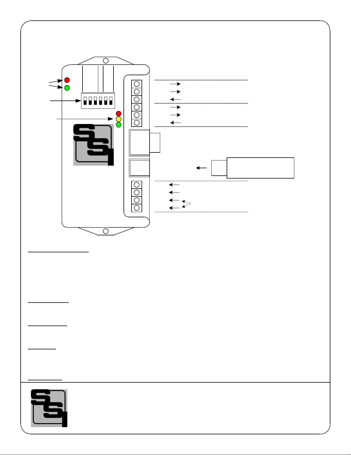
OUTPUTS - Two 3-wire isolated outputs are provided on the MPG-1, with output terminals K1, Y1 & Z1 and K2, Y2,
& Z2. Transient suppression for the contacts of the solid-state relays is provided internally. The output loads should
be limited to 100 mA at 120 VAC/VDC. Maximum power dissipation of each output is 800mW. The outputsare
protected by fuses F1& F2. One-tenth (1/10) Amp fuses (the maximum size) are supplied standard.
Z2
Y2
K2
Z1
Y1
K1
OUTPUT #2
OUTPUT #1
Zigbee USB
Dongle
Communication
Status LEDs
Output
Status LEDs Y
Z
Serial
Port RS-232 INTERFACE
to programming computer
V2.12 Firmware
Dip Switch

MPG-1 Wiring Diagram
s
3/27/16 N/A
DATE ORIGINAL
LATEST REVISION
SCALE
JOB NO.
REVISIONS
NO. DATE DESCRIPTION
WHB
DRAWNCHECKED
MPG-1 Wireless Pulse
Generator
Wiring Diagram
Brayden Automation Corp./
Solid State Instruments div.
6230 Aviation Circle
Loveland, CO 80538
(970)461-9600
(970)461-9205 fax
www.solidstateinstruments.com
MPG-1WiringDiagram.vsd
AMI
Electric
Meter
w/Zigbee
Radio K1
Z1
Y1
K2
Z2
Y2
Out 1
Out 2
MPG-1
Wireless Pulse
Generator
Service
Entrance
To Line
1 32 NEU
To Loads
Wireless
Data - 75' max
USB
RAVEn
dongle
To EMS
To SCADA
120-277VAC
Power
Supply
Connections
120
277
NEU
GND
Host
Port
F1
F2
MPG-1 Wireless Meter Pulse Generator
MPG-1 Metering Pulse Generator.vsd
Pairing the RAVEn Zigbee Radio Receiver
The RAVEn is a USB Zigbee Receiver device that must be paired with a Zigbee-equipped AMI electric meter. This may be
accomplished either with the assistance of the utility or on their website if they have the process automated. The process
for getting this done varies from utility to utility and not all utilities provide Zigbee radio availability. Contact your electric
utility to find out how their pairing process is accomplished. This process is also known as "provisioning". The RAVEn must
be powered to be paired with the meter and must be within range of the meter, usually within 75 feet.
The Meter must be programmed with the RAVEn's MAC address and Installation ID code. By being "paired", the meter and
the dongle have created a "network". The RAVEn dongle knows that it can only receive and accept information from that
particular electric meter. See the RAVEn instructions for more information on pairing the RAVEn with an electric meter.
Before Powering the MPG-1, install the RAVEn in the MPG-1's USB host port and set all system settings.
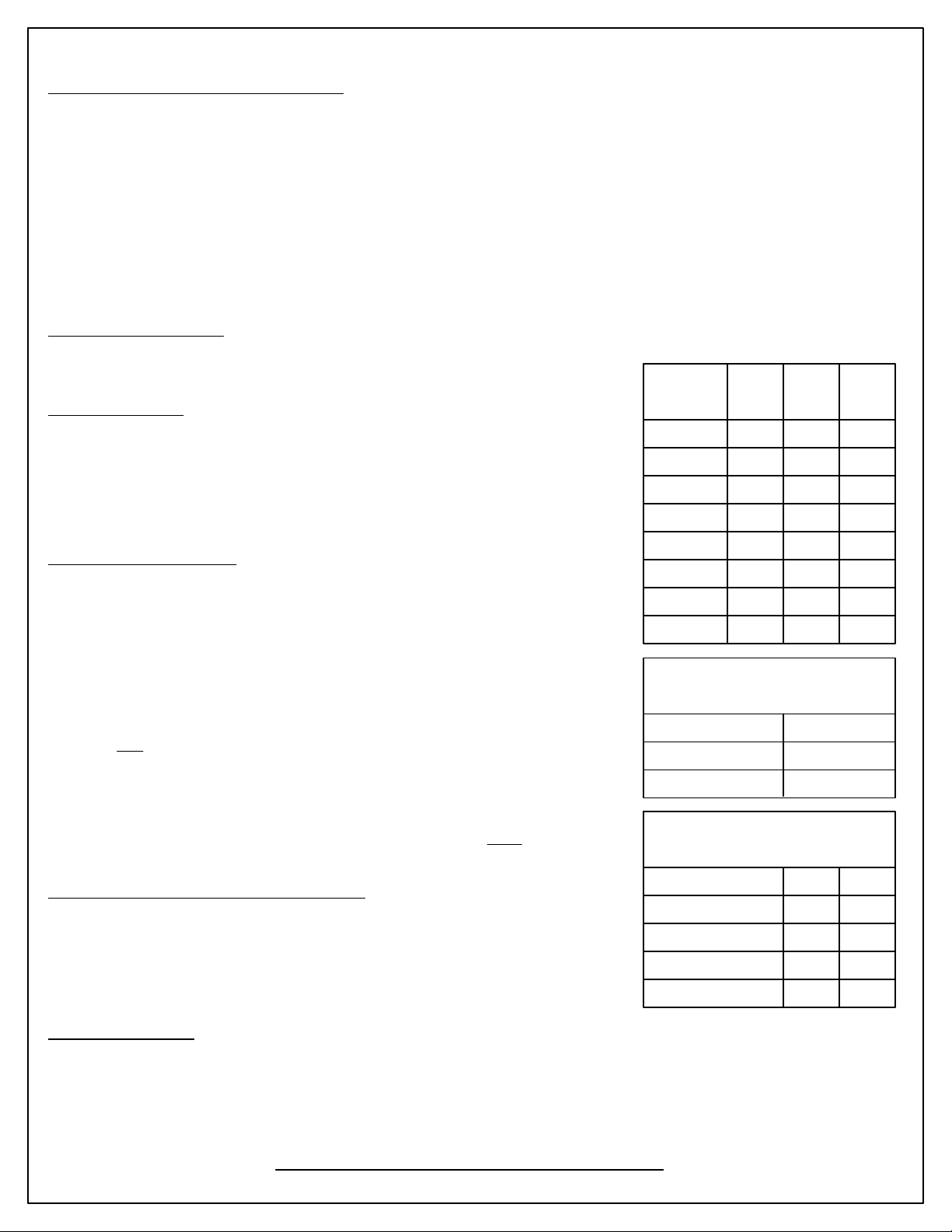
Set the MPG-1's Settings
Set the MPG-1's output pulse value, the pulse mode and the pulse timing by using
DIP Switch S1 on the MPG-1 board just above the microcontroller. Pulse
Value
(Wh) S1.1 S1.2 S1.3
2000
1000
500
250
100
50
25
10 DN DN DN
DN DN UP
DN UP DN
DN UP UP
UP DN DN
UP DN UP
UP UP DN
UP UP UP
Table 1
Pulse Value (PV)
Output Pulse Value
The pulse value (PV) is the number of watt-hours that each pulse is worth. The
MPG-1 can be set from 10 Wh to 2000 Wh per pulse. See Table 1 to select and
configure the desired pulse value for your application. Select a pulse output value
that you think will be appropriate for your application. A good starting point is 100
wh/pulse. You can adjust it up or down as needed. Larger facilities will require a
larger pulse value to keep from overranging the MPG-1's registers.
Set the Output Pulse Mode
The MPG-1 has two output modes, the 3-Wire (Form C) Toggle mode or the 2-Wire
(Form A) Fixed mode. Set S1.4 in the DOWN position for Toggle or in the UP
position for the Fixed mode. The toggle mode is the classic pulse output mode that
emulates the standard KYZ 3-Wire electric meter output. It toggles back and forth,
to the opposite state, each time a "pulse" is generated by the MPG-1. Even though
there are three wires, it is common to use K and Y, or K and Z, for many two-wire
systems that require or desire a generally symetrical 50/50 duty cycle pulse. The
toggle mode is used for systems that are doing demand control and need regularly
spaced pulses. The 3-Wire pulse value must be doubled if your device uses only
two wires and is only counting the closure as a pulse(not the opening also). Red and
Green Output LEDs show the output status. See additional information on Page 5.
In the Fixed mode, only the K-Y output is used. This is the standard 2-Wire system
where the output contact is normally-open until such time as a pulse is generated.
When a pulse is generated, the contact is closed for a selected fixed time interval in
milliseconds. Form A mode is generally associated with Energy measuring systems.
Set the Fixed Mode Output Pulse Width Time
If you are using the MPG-1 in the Fixed Mode, set the output closure time or pulse
width, selectable at 50mS, 100mS, 250mS and 500mS (1/2 second) as shown in
Table 3. Upon a pulse being generated, the K-Y terminals of each contact will close
for the selected number of milliseconds and light the RED LED only. This setting
applies only to the Form A output mode, and does not affect the toggle output
mode.
Pulse Width (mS) S1.5 S1.6
500
250
100
50 DN DN
DN UP
UP DN
UP UP
Table 3
Fixed Output Pulse Width (mS)
Output Mode S1.4
TOGGLE DN
Table 2
Output Pulse Mode
FIXED UP
Power up the MPG-1
Once the settings have been made on the DIP switch and the RAVEn has been inserted into the USB host port, power up
the MPG-1 board. The RED LED on the RAVEn dongle will flash for up to 60 seconds while it is establishing
communications with the meter. Once it has completed establishing communications, the RAVEn's RED LED will stay on
continuously. If this LED is not on continuously, the MPG-1 will not receive information from the RAVEn. If no valid
communication is received from the RAVEn, it will reset itself every 120 seconds (default reset time) trying to establish a
connection. The RED LED on the RAVEn MUST be lit continuously before moving on. If it is not, then it is not provisioned
correctly with the utility's meter. Do not proceed until this step is successfully completed.

MPG-1 Wireless Meter Pulse Generator (con't)
Communication LEDs
Upon power-up, the YELLOW comm LED should light indicating that the RAVEn dongle is correctly inserted, initialized
and communicating with the MPG-1's processor. Within about approximately 45 - 60 seconds, the GREEN comm LED will
blink each time a valid transmission is received from the meter. As long as valid transmissions are received by the
RAVEn dongle and successfully relayed to the MPG-1's processor, the Green comm LED will blink about once every 8-9
seconds. If the Green comm LED does not blink, that is an indication that the data transmissions from the meter are not
being received, may be corrupted, or in some manner are not valid transmissions. If the Green comm LED has been
blinking reliably every 8-9 seconds for some time, then stops for a while and then restarts again, this indicates that
transmissions are intermittent and sporatic, or generally means there is a problem in the RAVEn's ability to receive data
reliably from the meter. To correct this, change the proximity of the MPG-1 to the meter, move it closer to the meter if
possible and eliminate any metalic obstructions between the meter and the MPG-1. Also check to make sure that any
walls or barriers between the MPG-1 and the meter have as little metal in them as possible. In some applications you may
need line-of-sight.
Pulse Outputs
Outputs can be configured to be in the Toggle (Form C) mode or the Fixed (Form A) mode. Generally speaking, the
Form C mode can be used with either 2-Wire or 3-Wire Pulse receiving devices, while the Form A mode uses only a 2-
Wire interface to the downstream (receiving) pulse device. The choice would depend on the desired pulse format that the
receiving device prefers to see.
If the RAVEn is reliably receiving data from the meter and passing it on to the MPG-1's processor, then you should see the
Red and Green output LED's toggle each time the selected pulse value is reached, and the processor generates a pulse.
If the pulse output value is too high and pulses are too slow, then select a lower pulse value with Dip Switches S1.1-1.3.
(See Table 1 on Page 3).
If pulses are being generated too rapidly, select a higher pulse output value with Dip Switches S1.1-S1.3. The maximum
number of pulses per second is approximately 10, which means that the output's open and closed times are about 50mS
each in toggle mode. If the calculation by the MPG-1's processor is for pulse output timing that exceeds 15 pulses per
second, the MPG-1 will light the RED comm LED, indicating an overflow error, and that the pulse value is too small. It is
"latched" on so that the next time you look at it this RED LED will be lit. In this way, you can quickly determine if a pulse
output value is too small. In the optimum application, pulses would not exceed more than one pulse per 8 seconds. This
allows a very even and "normal" pulse rate that as closely as possible resembles an actual KYZ pulse output from the
meter.
The MPG-1 will "spread out" the pulses over the next 6-7 second period if a high enough watt-hour value is received in a
transmission to require that more than one pulse is generated. For example, suppose you have the Output Pulse Value of
10 wh selected. The next 8 second transmission yields 24 wh have been used. Since 24 watt-hours exceeds the 10 watt-
hour setting, two pulses must be generated. The first 10wh pulse will be generated immediately. About three seconds later
the second 10wh pulse will be generated. The remainder of four watt-hours stays in the accumulated energy register (AER)
awaiting the next transmission and the energy value of that transmission to be added to the contents of the AER. Another
example: Assume 25 wh/p Output Pulse Value. Let's say the next transmission is for 130 watt-hours. 130 is greater than
25, so 5 pulses will be outtputted over the next 7 seconds, approximately one each 1.4 seconds (7 seconds / 5 = 1.4
seconds). The remainder of 5 wh will stay in the AER awaiting the next transmission. Some trial and error may have to be
done for any particular building since pulse rates will change depending on maximum load.
Overranging the Output
As previously mentioned, if there are too many pulses calculated to be outputted in a 6-7 second interval than the MPG-1
can generate given the timing constraints, the MPG-1 will light the RED Comm LED. In this situation, simply increase the
pulse output value with Switches S1.1 thru S1.3, and cycle power to the MPG-1. This is intended to notify the user that a
higher pulse value is needed. As load is added to a building over time, there is some likelihood that this will occur so be
sure to consider this if/when you add load to the building. If an error condition occurs, set the Pulse Value for the next
highest pulse value. Remember to change the pulse constant of your receiving device as well, since pulses will now be
worth a higher watt-hour value. Cycle power to the MPG-1 to reset the RED Comm LED after increasing the pulse value.
WORKING WITH THE MPG-1 RELAY
OPERATING MODES: The MPG-1 Meter Pulse Generator allows the outputs to be
configured in either the "Toggle" or "Fixed" pulse output mode. In the Toggle mode, the
outputs alternate or toggle back and forth each time a pulse is generated. This is
synonomous with the classic 3-Wire Pulse metering and emulates the SPDT switch model.
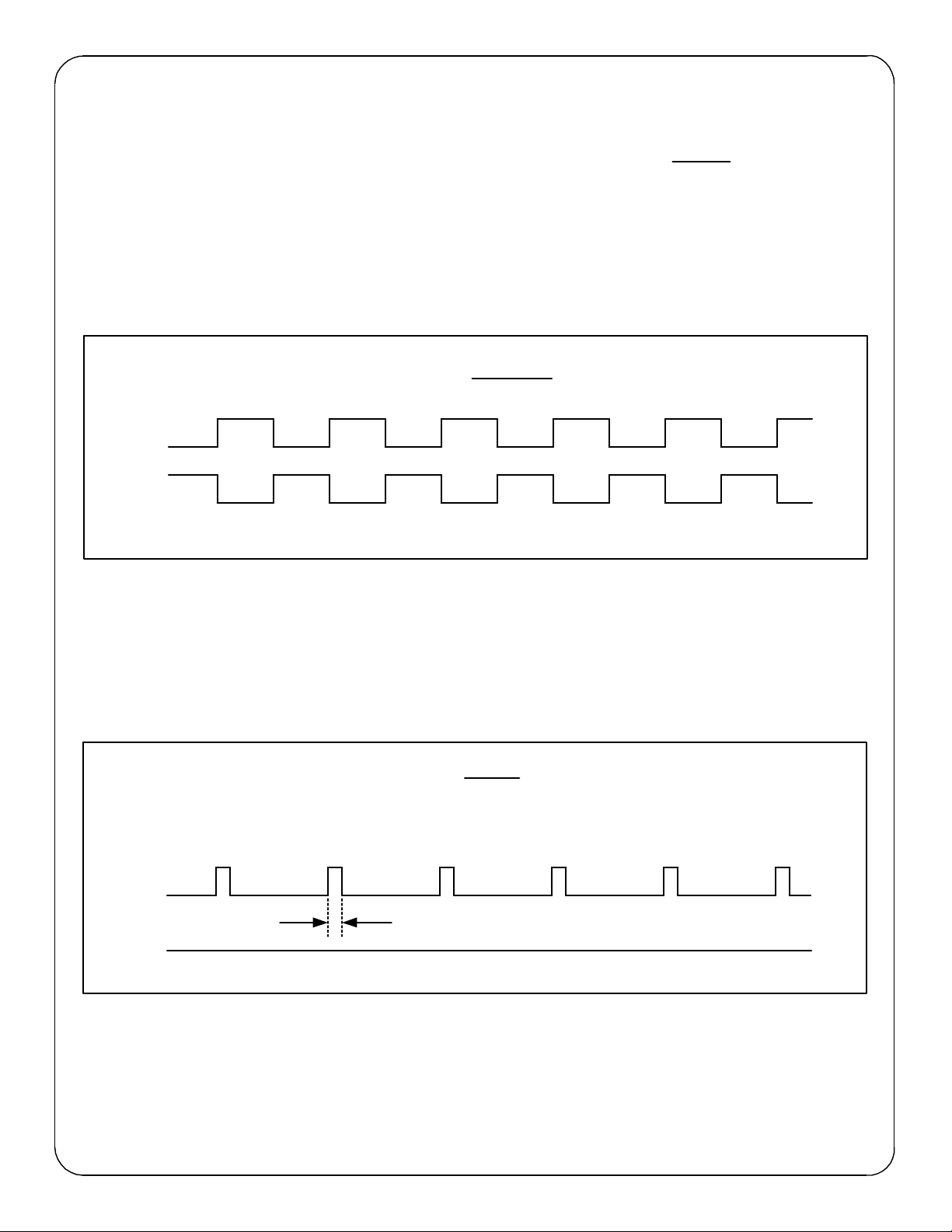
Figure 1 below shows the timing diagram for the "Toggle" output mode. KY and KZ
closures or continuity are always opposite of each other. In other words, when the KY
terminals are closed (on), the KZ terminals are open(off). This mode is best for timing
pulses to derive demand whether 2 or 3 wires are being used.
Contact the factory for technical support at (970)461-9600.
In the Fixed output mode, shown in Figure 2 below, an output pulse (K-Y closure only) is a
fixed width (T1) each time the output is triggered. The pulse width (closure time) is
determined by the setting of Dip Switches 5 and 6. (See Table 3 on Page 3.) This mode is
best for energy counting systems but generally is not best for systems doing demand control
where pulses are timed to derive instantaneous kW demand. The K-Z output is not used in
the normal/fixed mode. However, it is used in the Signed mode. See Page 6.
T1
Figure 2: 2-Wire Only FIXED Output Operation
K-Y Out Open
Closed
Open
Closed
K-Z Out
Figure 1: 2-Wire or 3-Wire TOGGLE Output Operation
K-Z Out
K-Y Out Open
Open
Closed
Closed
KY closure time
In Signed mode, with a Form A output mode selected, the K-Z output pulse represents
negative (or kWh received) energy. (See Page 6.)

MPG-1 Advanced Settings
MPG-1 Metering Pulse Generator.vsd
Meter Multiplier
If the building on which you are using the MPG-1 has an "Instrument-Rated" electric meter, AND the local utility has not
included this multiplier in the programming of the meter, you will have to enter the Meter Multiplier to the MPG-1's
program. To check out whether or not this is needed, (assuming your RAVEn is paired with the electric meter) either
install the RAVEn on a computer in the building and look at the serial output using a terminal program, or hook up the
MPG-1's serial port to a computer and view with a terminal program.
Determine the Multiplier of the facility's electric meter. If the meter is a self-contained meter, the multiplier is 1. The
default external multiplier in the MPG-1 is one (1), so you can skip this step. In an instrument-rated metering
configuration, the meter multiplier is normally the Current Transformer ("CT") ratio, but will also include the Potential
Transformer ("PT") Ratio, if PT's are used, usually only on larger applications. A 800 Amp to 5 Amp current transformer,
for example, has a ratio of 160. Therefore, the meter multiplier on a building with 800:5A CT's would be 160. The
Multiplier is normally printed on the monthly utility bill. If you cannot find it, call your utility and ask what the meter or
billing multiplier is.
If the utility's Zigbee transmission to the RAVEn includes the correct CT/PT multiplier value, you can skip this step also.
This is very rare on instrument-rated metering implementations however, since most utilities do not want to program the
multiplier into the meter due to conflicts with the billing process. If you are looking at the serial data received from the
meter you will be able to see what internal multiplier is being sent in every transmission. This will be in hexidecimal
format. What you're looking for is whether this is 1 or something else besides one. If, for instance, the multiplier is a
decimal 160, it will be transmitted by the meter to the RAVEn as a hexidecimal "A0". If the multiplier is one(1), you then
know that either this is a self-contained meter and a multiplier of 1 is correct, OR that this is an instrument-rated meter
and the utility does NOT send the CT/PT multiplier as part of the Zigbee transmission. If the latter is true, (and this is
the standard), you will have to program the meter multiplier into the MPG-1.
Setting up the Serial Port
Connect the Male-to-Female DB9 serial cable to the computer's serial port. Connect the other end to the MPG-1. With
TeraTerm, Puddy, ProComm or some similar terminal program, select the correct serial port to be used, set the baud
rate at 57600 and the terminal mode Receive as CR+LF. Also make sure that the local echo is enabled or "ON".
Turn on power to the MPG-1 and after the initialization process, the RED LED on the RAVEn should be lit continuously.
Assuming that the RAVEn is paired with the meter, is on, and is within 75' of the meter, then every 8 to 10 seconds, you
will see the following serial information received from the MPG-1:
-----------------------
Time Stamp: 21582e64
Demand: 000967
Multiplier: 00000001
Divisor: 000003e8
Energy (U): 5.35 Wh
Energy (F): 5.70 Wh
-----------------------
If the multiplier coming from the meter is 1 AND you know that the meter's multiplier is something other than one, you
will have to program the correct multiplier into the MPG-1 so that the true energy value is correct.
Programming the Multiplier
To change the multiplier in the MPG-1, use the Mcommand. Enter M160 and press <Enter> to change the multiplier to
160, as outlined in the application above. The serial link to the MPG-1 will return:
----------------------------------------
Multiplier: 160
----------------------------------------
You will not see the "M160" that you typed in on the screen unless the local echo is enabled on your terminal software.
To read back what the value of the multiplier currently in the MPG-1 is, press R and <Enter>. The serial link will return
the current multiplier stored in the MPG-1, along with all other system settings. For example, "Multiplier = 40" will be
returned if the current multiplier is 40. Case does not matter. The maximum multiplier is 99999 and must be an integer
(whole) number.
The serial port is used for both monitoring and programming the MPG-1. Therefore you have to enter your data between
outputs from the MPG-1.

MPG-1 Advanced Settings(cont)
MPG-1 Metering Pulse Generator.vsd
Programmable Output Pulse Value
One of the newest features of the MPG-1 is the capability to set the Output Pulse Value to a value other than those
available on the Dip Switch settings. The Programmable Output Pulse value may be programmed from 1 to 99999. The
default value of this register is zero (0) which enables the Dip Switches. Any value other than zero (0) disables the Dip
Switches and uses the value that is programmed using the "P" command over the MPG-1's serial port.
Hook up the MPG-1's serial port to a computer and use a terminal program to program a pulse value. (See "Setting up
the Serial Port" on the previous page.
Programming the Output Pulse Value with a Specific Value
To change the output pulse value in the MPG-1 to a value other than those available with the Dip Switches, use the P
command. Enter P1440 and press <Enter> for example to change the output pulse value to 1440 watt-hours or 1.44
kWh per pulse. The maximum value is 99999. The serial link to the MPG-1 will return:
------------------------------------------------
Pulse Value: 1440 watthours, (NV)"
------------------------------------------------
indicating that the value is 1440 watt-hours (1.44kWh) and it is stored in Non-Volatile memory.
Reading back all Programmable Parameters
To view the values of all programmable settings that are currently programmed into the MPG-1, press Rand <Enter>.
The serial link will return the following:
--------------------------------------------
Multiplier: 1
Pulse Value: 10 Watt-hours
Output Mode: Normal
Output Form: C
Dongle Mode: Normal
Reset Time: 120 seconds
Filter: Enabled
Filter Setting: 2 Samples
--------------------------------------------
Set Factory Defaults
If you find that you want to reset all parameters back to the factory defaults, simply press the Zkey and <Enter>. The
following parameters will default back to the factory settings as follows:
Multiplier=1
Pulse Value: 0 (DIP)
Reset Time: 120 seconds
Viewing the Firmware Version
In the event that the label on the MPG-1's microcontroller is lost or becomes unreadable, you can ask the MPG-1 what
firmware version it has in it wth the "V" command. Press V or v, then <Enter>and the serial link will return the following:
MPG V2.12
Dongle Readout Mode
There are two dongle readout modes available on the MPG-1, Normal and Echo. The Normal Mode is the default and
shows you the time stamp, the demand, the multiplier and the divisor coming from the meter. The Normal mode is set
by entering D followed by <Enter>.
----------------------------------------
Dongle Model: Normal
----------------------------------------
The Echo mode allows you to view the entire transmission coming from the meter the way it is received by the MPG-1's
microcontroller from the dongle in XML format. This mode may be useful in troubleshooting in the event of intermittent
transmissions from the meter. Enter a E followed by <Enter> to put the MPG-1 into the Dongle Echo mode.
The serial link will respond with:
----------------------------------------
Dongle Model: Echo
----------------------------------------
MPG-1 Advanced Settings (cont)
Bi-Directional Energy Flow (Signed Mode)
If you have energy flowing in both directions in the case of distributed energy resourses (solar, wind, etc), the MPG-1 can
provide both positive and negative pulses. This is known as the Signed mode, meaning that "kWh Delivered" (from the
utility to the customer) is positive or forward flow, and "kWh Received" (from the customer to the utility) is negative or
reverse flow.
The Pulse Value Setting (set by dip switches S1.1-S1.3) is the same for both positive and negative values.
To enter the functional or operational mode into the MPG-1, use the S and N commands. Press N <Enter> to set the
MPG-1 in the Normal mode. Press S <Enter> to set the MPG-1 in the Signed mode. The serial link to the MPG-1 will
return "Output Mode: Signed". To read what mode the MPG-1 is currently in, press R <Enter>. The serial link will return
the mode stored in the MPG-1. For example, "Output Mode: Normal" will be returned. Case does not matter.
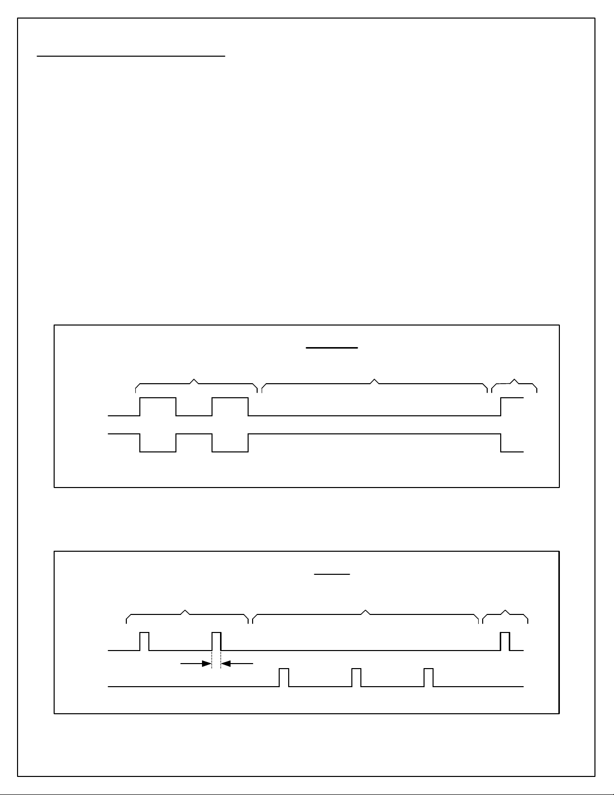
Form C Signed mode - A positive energy value received from the meter is added to the positive Accumulated Energy
Register(+AER). Negative energy values received are ignored. Only Form C toggle pulses are generated on the KYZ
output for Positive energy flow. See Figure 3 below.
Form A Signed mode - A positive energy value received is added to the positive Accumulated Energy Register(+AER).
A negative energy value received is added to the negative Accumulated Energy Register(-AER). When either register
equals or exceeds the Pulse Value setting, a pulse of the corresponding sign is outputted on the correct line. Pulses in
this mode are Form A (2-wire) "Fixed" only. K-Y pulses are Positive pulses and K-Z pulses are negative pulses. They
share a common K terminal on the output. Set the pulse value with dip switches S1.1 thru S1.3. Set the pulse width
using dip switches S1.5 and S1.6. See Figure 4 below.
T1
Figure 4: 2-Wire (FORM A) FIXED Output Operation
K-Y Out Open
Closed
Open
Closed
K-Z Out KY closure time
In Signed mode, with a Form A output mode selected, the K-Y output pulse represents
positive (or kWh delivered) energy; K-Z output pulse represents negative (or kWh received)
energy.
(Positive)
(Negative)
Figure 3: 3-Wire (FORM C) TOGGLE Output Operation
K-Z Out
K-Y Out Open
Open
Closed
Closed
Positive Energy Pulse Outputs Only
Positive and Negative Energy Pulse Outputs
In Signed mode, with a Form C output mode selected, the K-Y and K-Z output pulses
represent positive (or kWh delivered) energy; Negative (or kWh received) energy is ignored.
Positive Flow Positive FlowNegative Flow
Positive Flow Positive FlowNegative Flow

Filter Mode Enable/Disable (F)
The MPG-1 includes a filtering mode to smooth out the erratic communications from the electric meter which happen for a
number of reasons. This mode allows you to use 2 to 10 samples, each at about 8 seconds long, to average usage, and
thus kW demand, over the selected interval from approximately 16 to 80 seconds. Depending on the device receiving the
pulses and the methodology it uses to interpret them, this can be a great help in representing the real kW demand and
eliminate the quantitization problem caused.
To enable the filter mode enter F1 and <ENTER>. The serial link on the MPG-1 will return the following:
----------------------------------------
Filter: Enabled
----------------------------------------
To disable the filter mode enter F0 and <ENTER>. The serial link on the MPG-1 will return the following:
----------------------------------------
Filter: Disabled
----------------------------------------
Set the number of Filter Samples (L)
This setting sets the number of samples used by the Filter Mode filtering the energy value over a desired number of
samples, from 2 to 10. The default is 2. To set the number of samples Enter L5 then <ENTER>. The serial link on the
MPG-1 will return the following:
----------------------------------------
Filter Setting: 5
----------------------------------------
XML Dongle Reset
V2.11 Firmware implements a XML Dongle reset feature that will reset the dongle if the dongle received a pre-defined
number of transmissions at a rate less than 5 seconds. The "X" or "x" command is followed by a number from 2 to 10. A
X0<CR> command will disable the reset feature. The default number of time delay violations is 2.
List of MPG-1 Commands (?)
For help in selecting or using the serial commands with the MPG-1, simply press the ? key. The serial link on the MPG-1
will return a full list of the commands.
mXXXXX<CR> or MXXXXX<CR> - Set multiplier (XXXXX is 1 to 99999).
pXXXXX<CR> or PXXXXX<CR> - Set pulse value, Watt-hours (XXXXX is 0 to 99999)
tXXX<CR> or TXXX<CR> - Set Reset Time, seconds (XXX is 30 to 600).
lXX<CR> or LXX<CR> - Set Filter # of samples (XX is 2 to 10).
'f0<CR>' or 'F0<CR>' - Disable Filter.
'f1<CR>' or 'F1<CR>' - Enable Filter.
'r<CR>' or 'R<CR>' - Read Parameters.
's0<CR>' or 'S0<CR>' - Set into Normal mode (positive only with Form A or C set by DIP4)
's1<CR>' or 'S1<CR>' - Set into Signed mode (positive/negative with only Form A)
'd0<CR>' or 'D0<CR>' - Set into Dongle Normal mode
'd1<CR>' or 'D1<CR>' - Set into Dongle Echo mode
'z<CR>' or 'Z<CR>' - Set Factory Defaults
'v<CR>' or 'V<CR>' - Query Firmware version
'x<CR>' or 'X<CR>' - XML Dongle Reset
Popular Inverter manuals by other brands


SolaX Power
SolaX Power X3-Retro Fit Series Quick installation guide

SOLIS
SOLIS RHI Series instruction manual

Resol
Resol DeltaSol AL E Manual for the specialised craftsman

Effekta
Effekta KS5 Series Installation and operation manual

Sinclair
Sinclair SDV5 Series User & installation manual

PrimeVOLT
PrimeVOLT PV 7KTL-D1P user manual


