manuals.online logo
Brands
  1. Home
  2. •
  3. Brands
  4. •
  5. Toshiba
  6. •
  7. Inverter
  8. •
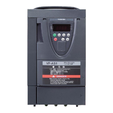
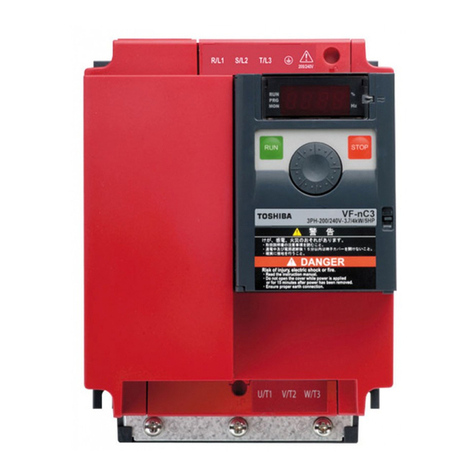
  9. Toshiba VF-NC3C User manual

Toshiba VF-NC3C User manual

INSTRUCTION MANUAL
VF-NC3C
<NOTICE>
1. THIS INSTRUCTION MANUAL IS
SUBJECTED TO BE CHANGED WITHOUT
NOTICE.
2. THIS INSTRUCTION MANUAL IS FOR
STUDY REFERENCES ONLY.
FOR REFERENCES ONLY VFNC3C ENGLISH MANUAL NOT SUBJECTED FOR RESALE
B-1
2
2. Connection
Warning
Disassembly
prohibited
Never disassemble, modify or repair.
This can result in electric shock, fire and injury. For repairs, call your sales agency.
Prohibited
Don't stick your fingers into openings such as cable wiring hole and cooling fan covers.
This can result in electric shock or other injury.
Don't place or insert any kind of object into the inverter (electrical wire cuttings, rods, wires). This can
result in electric shock or fire.
Do not allow water or any other fluid to come in contact with the inverter.
That may result in electric shock or fire.
Caution
Prohibited
When transporting or carrying, do not hold by the front panel covers.
The covers may come off and the unit will drop out resulting in injury.
2.1 Cautions on wiring
Warning
Prohibited
Never remove the terminal cover when power is on or open door if enclosed in a cabinet.
The unit contains many high voltage parts and contact with them will result in electric shock.
Mandatory
action
Turn power on only after attaching the front cover or closing door if enclosed in a cabinet.
If power is turned on without the terminal cover attached or closing door if enclosed in a cabinet. This
can result in electric shock or other injury.
Electrical construction work must be done by a qualified expert.
Connection of input power by someone who does not have that expert knowledge may result in fire or
electric shock.
Connect output terminals (motor side) correctly.
If the phase sequence is incorrect, the motor will operate in reverse and that may result in injury.
Wiring must be done after installation.
If wiring is done prior to installation that may result in injury or electric shock.
The following steps must be performed before wiring.
(1) Shut off all input power.
(2) Wait at least 15 minutes and check to make sure that the charge lamp is no longer lit.
If these steps are not properly performed, the wiring will cause electric shock.
Tighten the screws on the terminal board to specified torque.
If the screws are not tightened to the specified torque, it may lead to fire.
FOR REFERENCES ONLY VFNC3C ENGLISH MANUAL NOT SUBJECTED FOR RESALE
B-2
2
2
Warning
Be Grounded
Ground must be connected securely.
If the ground is not securely connected, it could lead to electric shock or fire when a malfunction or
current leak occurs.
Caution
Prohibited
Do not attach devices with built-in capacitors (such as noise filters or surge absorber) to the output
(motor side) terminal.
This could cause a fire.
Preventing radio noise
To prevent electrical interference such as radio noise, separately bundle wires to the main circuit's power
terminals (R/L1, S/L2, T/L3) and wires to the motor terminals (U/T1, V/T2, W/T3).
Control and main power supply
The control power supply and the main circuit power supply for this inverter are the same.
If a malfunction or trip causes the main circuit to be shut off, control power will also be shut off. When
checking the cause of the malfunction or the trip, use the trip holding retention selection parameter.
Wiring
Because the space between the main circuit terminals is small use sleeved pressure terminals for the
connections. Connect the terminals so that adjacent terminals do not touch each other.
For ground terminal use wires of the size that is equivalent to or larger than those given in table 10.1
and always ground the inverter (400V voltage class: C type ground).
Use as large and short a ground wire as possible and wire it as close as possible to the inverter.
For the sizes of electric wires used in the main circuit, refer to the table in section 10.1.
The length of the main circuit wire in table 10.1 should be no longer than 30 meters. If the wire is longer
than 30 meters, the wire size (diameter) must be increased.
FOR REFERENCES ONLY VFNC3C ENGLISH MANUAL NOT SUBJECTED FOR RESALE
B-3
2
2.2 Standard connections
Warning
Prohibited
Do not connect input power to the output (motor side) terminals (U/T1, V/T2, W/T3).
Connecting input power to the output could destroy the inverter or cause a fire.
First shut off input power and wait at least 15 minutes before touching wires on equipment (MCCB) that
is connected to inverter power side.
Touching the wires before that time could result in electric shock.
Mandatory
action
Set parameter  when VI terminal is used as logic input terminal.
If it is not set, it could result in malfunction.
Be Grounded
Ground must be connected securely.
If the ground is not securely connected, it could lead to electric shock or fire when a malfunction or
current leak occurs.
FOR REFERENCES ONLY VFNC3C ENGLISH MANUAL NOT SUBJECTED FOR RESALE
B-4
2
2
2.2.1 Standard connection diagram 1
This diagram shows a standard wiring of the main circuit.
MCCB R/L1
S/L2
T/L3
U/T1
V/T2
W/T3
Motor
F
R
S1
S2
CC
P24
OUT
NO
CC
FM CC VI P5
++
-
-
PA/+ PB
Meter Voltage signal: 0-5V/0-10V
(Current signal: 4-20mA)
External potentiometer (1k-10k)
Protective function
activation output
Ry
VF-nC3C
Power
circuit
Forward
Reverse
Preset-speed 1
Preset-speed 2
Common
Standard connection diagram - SINK (Negative) (common:CC)
7.5V-1mA
(or 0-10V/4-20mA)
Low-speed
signal output
*2
*1: VFNC3C-4004P, 4007P models don’t
have the PA/+ and the PB terminals
and cannot be used with Braking
resistor.
*2: When using the OUT output terminal in
sink logic mode, short the NO and CC
terminals.
Control
circuit
I M
Frequency
meter
(ammeter)
Operation panel
FLC
FLB
FLA
*3: When external potentiometer is connected
by using P5 terminal, set the parameter
f 1 0 9 =3.
RS485
communication
connector
*4
*4: When VI terminal is used as a logic
input terminal, refer to page B-10.
Main circuit power supply
3ph-400V class: three-phase 380-460V
-50/60Hz
*3
Braking resistor(Option)*1
FOR REFERENCES ONLY VFNC3C ENGLISH MANUAL NOT SUBJECTED FOR RESALE
B-5
2
2.2.2 Standard connection diagram 2
MCCB R/L1
S/L2
T/L3
U/T1
V/T2
W/T3
Motor
F
R
S1
S2
OUT
NO
CC
++
-
-
Meter
External potentiometer (1k-10k)
Control
circuit
Protective function
activation output VF-nC3C
Power
circuit
Forward
Reverse
Preset-speed 1
Preset-speed 2
Standard connection diagram - SOURCE (Positive) (common:P24)
7.5V-1mA
(or 0-10V/4-20mA)
FM CC VI P5
Voltage signal: 0-5V/0-10V
(Current signal: 4-20mA)
Low-Speed
signal output
*2
Ry
*2: When using the NO output terminal in
source logic mode, short the P24 and
OUT terminals.
I M
Frequency
meter
(ammeter)
RS485
communication
connector
Operation panel
FLC
FLB
FLA
*3: When external potentiometer is connected
by using P5 terminal, set the parameter
f 1 0 9 =3.
*4
*3
Main circuit power supply
3ph-400V class: three-phase 380-460V
-50/60Hz
*4: When VI terminal is used as a contact
input terminal, refer to page B-10.
P24 Common
*1: VFNC3C-4004P, 4007P models don’t
have the PA/+ and the PB terminals
and cannot be used with Braking
resistor.
PA/+ PB
Braking resistor(Option)*1
FOR REFERENCES ONLY VFNC3C ENGLISH MANUAL NOT SUBJECTED FOR RESALE
B-6
2
2
2.3 Description of terminals
2.3.1 Power circuit terminals
This diagram shows an example of wiring of the main circuit. Use options if necessary.
Power supply and motor connections
Connections with peripheral equipment
Motor
Power
supply
Inverter
Braking resistor
No-fuse
braker
R/L1
S/L2
T/L3
PA/+
PB
V/T2
U/T1
W/T3
IM
Magnetic
contactor
Input AC
reactor
Zero-phase
reactor
Note 1: The PA/+ and PB terminals are not provided for VFNC3C-4004P, 4007P models.
Power supply
S/L2
T/L3
Motor
No-fuse
breaker
Connect the power
cables to R/L1, S/L2,
and T/L3.
Connect the motor
cables to U/T1, V/T2
and W/T3.
VF-nC3C
E
U/T1
V/T2
W/T3
R/L1
FOR REFERENCES ONLY VFNC3C ENGLISH MANUAL NOT SUBJECTED FOR RESALE
B-7
2
Power circuit
Terminal symbol
Terminal function
Grounding terminal for connecting inverter. There are 3 terminals in total.
R/L1,S/L2,T/L3
400V class: three-phase 380 to 460V-50/60Hz
U/T1,V/T2,W/T3
Connect to a (three-phase induction) motor.
PA/+,PB
Connect to braking resistors.
Change parameters ,,, if necessary.
The arrangements of power circuit terminals are different from each range.
Refer to section 1.3.3.1) for details.
2.3.2 Control circuit terminals
The control circuit terminal board is common to all equipment.
Regarding to the function and specification of each terminal, please refer to the following table.
Refer to section 1.3.3.3) about the arrangement of control circuit terminals.
Control circuit terminals
Terminal
symbol
Input /
output
Function
Electrical
specifications
Inverter internal circuits
F
Input
Multifunction programmable logic input
Shorting across F-CC causes
forward rotation; open causes slow-
down and stop. (When Standby ST
is always ON)
3 different functions can be
assigned.
No voltage
logic input
24Vdc-5mAor less
*Sink/Source
selectable using
parameter 
(In case of sink
logic is the left)
2.2k
+24V
ON:
Sink
OFF:
Source
2.2k
470
F
R
S1
S2
CC
OFF:
External
24V
P24
R
Input
Shorting across R-CC causes
reverse rotation; open causes slow-
down and stop. (When Standby ST
is always ON)
3 different functions can be
assigned.
S1
Input
Shorting across S1-CC causes
preset speed operation.
2 different functions can be
assigned.
S2
Input
Shorting across S2-CC causes
preset speed operation.
2 different functions can be
assigned.
FOR REFERENCES ONLY VFNC3C ENGLISH MANUAL NOT SUBJECTED FOR RESALE
B-8
2
2
Terminal
symbol
Input /
output
Function
Electrical
specifications
Inverter internal circuits
CC
Common
to Input /
output
Control circuit's equipotential terminal (2
terminals)
CC
P5
Output
Analog power supply output
5Vdc
(permissible load
current: 10mA)
100
+5V
P5
CC
V I
Input
Multifunction programmable analog input.
Factory default setting: 0-10Vdc (1/1000
resolution) and 0-60Hz (0-50Hz)
frequency input.
The function can be changed to 0-20mAdc
(4-20mA) current input by parameter 
=1 setting.
0-5Vdc (1/1000 resolution) voltage input
by parameter  =3 setting.
Switch to this setting when external
potentiometer is connected by using P5
terminal.
By changing parameter f109=2 setting,
this terminal can also be used as a
multifunction programmable logic input
terminal. When using the sink logic, be
sure to insert a resistor between P24-VIA
(4.7 k-1/2 W).
5V/10Vdc
(internal impedance:
40k)
4-20mA
(internal
impedance: 250)
Note 1)
1.6k
+5V
250
39.2k
47k
47k
ON:Current
OFF:Voltage
ON:10V
OFF:5V
VI
CC
FM
Output
Multifunction programmable analog
output. Standard default setting: output
frequency.
The function can be changed to 0-10Vdc
voltage or 0-20mAdc (4-20mA) current
output by parameter  setting.
1mAdc full-scale
ammeter
0-10V DC volt
meter
0-20mA(4-20mA)
DC ammeter
Permissible load
resistance:
750Ω or less
0-10V DC volt
meter
2.7k
+24V
68
121
ON:Current
+
–
ON:Voltage
Meter
ON:Meter
+
–
FM
CC
Note 1) Be careful, if 4-20mA is selected, when the inverter's power is ON, the internal impedance is 250Ω, but when the power
is OFF, the internal impedance increases very much to approximately 40kΩ.
FOR REFERENCES ONLY VFNC3C ENGLISH MANUAL NOT SUBJECTED FOR RESALE
B-9
2
+24V
Over current
protection circuit
P24
CC
OFF:f 1 2 7 =200
Terminal
symbol
Input /
output
Function
Electrical
specifications
Inverter internal circuits
P24
Output
24Vdc power output
24Vdc-100mA
Input
This terminal can be used as an external
24Vdc input for logic input terminal by
changing parameter f127=200.
-
OUT
NO
Output
Multifunction programmable open
collector output. Standard default settings
detect and output low speed signal.
Multifunction output terminals to which
two different functions can be assigned.
The NO terminal is an isoelectric output
terminal. It is insulated from the CC
terminal.
By changing parameter settings, these
terminals can also be used as
multifunction programmable pulse train
output terminals.
Open collector output
24Vdc-100mA
To output pulse
trains,
a current of 10mA
or more needs to
be passed.
Pulse frequency
range:
38~1600pps
OUT
NO
10
FLA
FLB
FLC
Note 2)
Output
Multifunction programmable relaycontact
output.
Detects the operation of the inverter's
protectionfunction.
Contact across FLA-FLC isclosed and FLB-
FLC is opened during protection function
operation.
250Vac-2A
(cos=1)
: at resistance
load
30Vdc-1A
250Vac-1A
(cos=0.4)
Min.permissible
load
5Vdc-100mA
FLA
FLC
FLB
RY
+24V
Note 2) Please use the OUT terminal as much as possible when the programmable controller is connected.
FOR REFERENCES ONLY VFNC3C ENGLISH MANUAL NOT SUBJECTED FOR RESALE
B-10
2
2
SINK (Negative) logic/SOURCE (Positive) logic (When the
inverter's internal power supply is used)
Current flowing out turns control input terminals on. These are called sink logic terminals.
The general used method in Europe is source logic in which current flowing into the input terminal turns it
on.
Sink logic is sometimes referred to as negative logic, and source logic is referred to as positive logic.
Each logic is supplied with electricity from either the inverter's internal power supply or an external power
supply, and its connections vary depending on the power supply used.
Setting of sink/source logic varies depending on the setup menu setting. (Refer to section 11.5)
Sink/source logic can be switched by parameter .
<Examples of connections when the inverter's internal power supply is used>
CC
NO
Source (Positive) logic
Inverter
P24
F
Programmable
controller
Common
Common
Output
Input
Input
24VDC
Output
Sink (Negative) logic
F
CC
Common
Output
Input
24VDC
Output
OUT
P24
24VDC
CC
NO
OUT
P24
24VD
Input
Common
Inverter
Programmable
controller
f 1 2 7 =0
f 1 2 7 =100
FOR REFERENCES ONLY VFNC3C ENGLISH MANUAL NOT SUBJECTED FOR RESALE
B-11
2
SINK (Negative) logic (When an external power supply is used)
The P24 terminal is used to connect to an external power supply or to separate a terminal from other input
or output terminals.
<Examples of connections when an external power supply is used>
Sink (Negative) logic
f 1 2 7 =200
F
Output
Input
24VDC
Output
OUT
NO
24VDC
Input
Common
Inverter
Programmable
controller
P24
Common
CC
24VDC
OFF
(f 1 2 7 =200)
FOR REFERENCES ONLY VFNC3C ENGLISH MANUAL NOT SUBJECTED FOR RESALE
B-12
2
2
Selecting the functions of the VI terminal between analog input and logic input
The functions of the VI terminal can be selected between analog input and logic input by changing
parameter settings (). (Factory default setting: Analog input 0-10V)
Be sure to connect a resistor between P24 and VI terminals in case of sink logic, between VI and CC
terminals in case of source logic. (Recommended resistance: 4.7k-1/2W)
When using VI terminal as a logic input terminal, set the parameter =and connect as following
schematics.
If no resistor is inserted, logic input will be left always ON, which is very dangerous.
Switch between analog input and logic input before connecting the terminals to the control circuit terminals.
Otherwise the inverter or devices connected to it may be damaged.
<Sink logic>
<Source logic>
4.7kΩ
P24
V I
CC
4.7kΩ
P24
V I
CC
FOR REFERENCES ONLY VFNC3C ENGLISH MANUAL NOT SUBJECTED FOR RESALE
C-1
3
2
3. Operations
Caution
Prohibited
Do not touch inverter terminals when electrical power is going to the inverter even if the motor is
stopped.
Touching the inverter terminals while power is connected to it may result in electric shock.
Do not touch switches when the hands are wet and do not try to clean the inverter with a damp cloth.
Such practices may result in electric shock.
Do not go near the motor in alarm-stop status when the retry function is selected.
The motor may suddenly restart and that could result in injury.
Take measures for safety, e.g. attaching a cover to the motor, against accidents when the motor
unexpectedly restarts.
Mandatory
action
Turn the input power on only after attaching the terminal block cover (i.e., after closing the cabinet
doors).
If the input power is turned on without the terminal block cover attached (i.e., without closing the
cabinet doors), this may result in electric shock.
If the inverter begins to emit smoke or an unusual odor, or unusual sounds, immediately turn power off.
If the equipment is continued in operation in such a state, the result may be fire. Call your local sales
agency for repairs.
Always turn power off if the inverter is not used for long periods of time.
Turn the input power on only after attaching the terminal block cover.
When enclosed inside a cabinet and used with the terminal block cover removed, always close the
cabinet doors first and then turn the power on. If the power is turned on with the terminal block cover or
the cabinet doors open, this may result in electric shock.
Make sure that operation signals are off before resetting the inverter after malfunction.
If the inverter is reset before turning off the operating signal, the motor may restart suddenly causing
injury.
Caution
Contact
prohibited
Do not touch heat radiating fins or discharge resistors.
These devices are hot, and you'll get burned if you touch them.
Prohibited
Observe all permissible operating ranges of motors and mechanical equipment. (Refer to the motor's
instruction manual.)
Not observing these ranges may result in injury.
FOR REFERENCES ONLY VFNC3C ENGLISH MANUAL NOT SUBJECTED FOR RESALE
C-2
3
2
3.1 How to Set the Setup Menu
Warning
Mandatory
action
If incorrect setting, the drive may has some damage or unexpected movement. Be sure to set the
setup parameter correctly.
Set the setup menu according to the logic for control input signals used and the base frequency of the motor
connected. (If you are not sure which setup menu should be selected region codes and what values should be
specified, consult your distributer.)
Each setup menu automatically sets all parameters relating to the logic for control input signals used and the base
frequency of the motor connected. (See the table on the following page.)
Follow these steps to change the setup menu [Example: Selecting a region code to ]
Panel operated
LED display
Operation

Power on. (set is blinking)

Turn the setting dial, and select region code ""
(Europe).
 
Press the center of the setting dial to determine the
region.

The operation frequency is displayed (Standby).
☆When changing the region selected in the setup menu, the setup menu can be called again by the following
method. Note, however, that all parameter settings return to standard defaults.
Set parameter  to "".
Set parameter  to "".
☆The parameter settings in the table on the following page can be changed individually even after they are
selected in the setup menu.
eu
asia
jp
usa
FOR REFERENCES ONLY VFNC3C ENGLISH MANUAL NOT SUBJECTED FOR RESALE
C-3
3
2
Values set by each setup parameter
Title
Function

(Mainly in
Europe)

(Mainly in North
America)

(Mainly in Asia,
Oceania)

(Mainly in Japan)

Maximum
frequency
50.0(Hz)
60.0(Hz)
50.0(Hz)
80.0(Hz)
/
/

Frequency
settings
50.0(Hz)
60.0(Hz)
50.0(Hz)
60.0(Hz)

VI input point 2
frequency
50.0(Hz)
60.0(Hz)
50.0(Hz)
60.0(Hz)
/

Base frequency
voltage 1, 2
230(V)
230(V)
230(V)
200(V)

Sink/source
switching

Supply voltage
correction
(output voltage
limitation)
2
2
2
3

Motor rated
speed
1410(min-1)
1710(min-1)
1410(min-1)
1710(min-1)
F, R, S1, S2
CC
0 [ Sink logic ]
(Negative common)
(Common : CC)
F, R, S1, S2
P24
100 [ Source logic ]
(Positive common)
(Common : P24)
FOR REFERENCES ONLY VFNC3C ENGLISH MANUAL NOT SUBJECTED FOR RESALE
C-4
3
2
3.2 Simplified Operation of the VF-nC3
The procedures for setting operation frequency and the methods of operation can be selected from the following.
Run / Stop
:
(1) Run and stop using the panel keypad
(2) Run and stop using external signals to terminal
board
Setting the frequency
:
(1) Setting using setting dial
(2) Setting using external signals to terminal board
(0-5V/0-10Vdc, 4-20mAdc)
Use the basic parameters  (command mode selection) 
and (frequency setting mode selection) for selection.
[Parameter setting]
Title
Function
Adjustment range
Default setting

Command mode selection
0: Terminal board
1: Panel keypad (including remote
keypad)
2: RS485 communication
1

Frequency setting mode
selection
0: Terminal board VI
1: Setting dial 1 (press in center to save)
2: Setting dial 2 (save even if power is off)
3: RS485 communication
4: -
5: UP/DOWN form external logic input
2
☆fmod=2(setting dial 2) is the mode where after the frequency is set by the setting dial, the frequency is
saved even if the power is turned off.
☆Refer to section 5.5 in E6581595 for details about =and .
FOR REFERENCES ONLY VFNC3C ENGLISH MANUAL NOT SUBJECTED FOR RESALE
C-5
3
2
3.2.1 How to run and stop
[Example of a  setting procedure]
Panel operation
LED display
Operation

Displays the operation frequency (operation stopped).
(Whenstandard monitor display selection =[Operationfrequency])

Displays the first basic parameter [History ()].

Turn the setting dial, and select "".

Press the center of the setting dial to read the parameter value.
(Standard default: ).

Turn the setting dial to change the parameter value to (terminal
block).

Press the center of the setting dial to save the changed parameter.
 and the parameter set value are displayed alternately.
(1)Run and stop using the panel keypad (=)
Use the and keys on the panel keypad to start and stop the motor.
: Motor runs. : Motor stops.
☆The direction of rotation is determined by the setting of parameter  (forward run, reverse run
selection). (: forward run, : reverse run)
☆To switch between forward run and reverse run from the remote keypad (option), the parameter 
(forward run, reverse run selection) needs to be set to or . (Refer to section 5.7 in E6581595)
(2)RUN / STOP by means of an external signal to the terminal board (=):
Sink (Negative) logic
Use external signals to the inverter terminal board to start and stop the motor.
Frequency
ON
OFF
F-CC
Slow down
and stop
F
Short and terminals: run forward
Open and terminals: slow down and stop
CC
F
CC
MODE
RUN
STOP
RUN
STOP
FOR REFERENCES ONLY VFNC3C ENGLISH MANUAL NOT SUBJECTED FOR RESALE
C-6
3
2
(3)Coast stop
The standard default is slowdown stop. To make a
coast stop, assign "6 (ST)" to an idle terminal.
Change to =.
For coast stop, open the ST-CC when stopping the
motor in the state described at left.The monitor on the
inverter at this time will display .
A coast stop can also be made by assigning "
(FRR)" to an idle terminal.
When doing this, a coast stop is done by FRR and CC
both turning on.
Motor
speed
ON
OFF
ON
OFF
F-CC
ST-CC
Coast stop
3.2.2 How to set the frequency
[Example of  setting procedure]: Setting the frequency setting destination to the terminal block
Panel operation
LED display
Operation

Displays the operation frequency (operation stopped).
(Whenstandard monitor displayselection =[Operation
frequency])

Displays the first basic parameter [History ()].

Turn the setting dial, and select "".

Press the center of the setting dial to read the parameter value.
(Standard default: ).

Turn the setting dial to change the parameter value to (terminal block
VI).

The parameter value is written. and the parameter value are
displayed alternately several times.
* Pressing the MODE key twice returns the display to standard monitor mode (displaying operation frequency).
(1)Setting using the keypad (=or )
: Moves the frequency up : Moves the frequency down
Example of operating from the panel (=: press in center to save)
Panel operation
LED display
Operation

Displays the operation frequency.
(Whenstandardmonitordisplayselection=[Operationfrequency])

Set the operation frequency. (The frequency will not be saved if the
power is turned off in this state.)

Save the operation frequency.  and the frequency are displayed
alternately.
MODE
FOR REFERENCES ONLY VFNC3C ENGLISH MANUAL NOT SUBJECTED FOR RESALE
C-7
3
2
Example of operating from the panel (=: save even if power is off)
Panel operation
LED display
Operation

Display the operation frequency.
(When standard monitor display selection is set as =
[operation frequency])

Set the operation frequency.
-

The frequency will be saved even if the power is turned off in this
state.

Other Toshiba Inverter manuals

Toshiba TOSVERT VF-P7 User manual

Toshiba

Toshiba TOSVERT VF-P7 User manual

Toshiba TOSVERT VF-S11 User manual

Toshiba

Toshiba TOSVERT VF-S11 User manual
Toshiba TOSVERT VF-FS1 Series Parts list manual

Toshiba

Toshiba TOSVERT VF-FS1 Series Parts list manual

Toshiba TOSVERT VF-S15 series User manual

Toshiba

Toshiba TOSVERT VF-S15 series User manual

Toshiba TOSVERT VF-S15 series Parts list manual

Toshiba

Toshiba TOSVERT VF-S15 series Parts list manual

Toshiba TOSVERT VF-MB1 Parts list manual

Toshiba

Toshiba TOSVERT VF-MB1 Parts list manual

Toshiba VLP Technology Q9 Plus User manual

Toshiba

Toshiba VLP Technology Q9 Plus User manual

Toshiba TOSVERT VF-AS1 Series User manual

Toshiba

Toshiba TOSVERT VF-AS1 Series User manual

Toshiba HX7+ ASD User manual

Toshiba

Toshiba HX7+ ASD User manual

Toshiba TOSVERT VF-A7 User manual

Toshiba

Toshiba TOSVERT VF-A7 User manual

Toshiba TOSVERT VF-S11 User manual

Toshiba

Toshiba TOSVERT VF-S11 User manual
Toshiba TOSVERT VF-MB1 User manual

Toshiba

Toshiba TOSVERT VF-MB1 User manual

Toshiba TOSVERT VF-S11 Configuration guide

Toshiba

Toshiba TOSVERT VF-S11 Configuration guide

Toshiba P9 ASD User manual

Toshiba

Toshiba P9 ASD User manual

Toshiba TOSVERT VF-FS1 Series User manual
Toshiba

Toshiba TOSVERT VF-FS1 Series User manual

Toshiba TOSVERT VF-AS3 Instruction manual

Toshiba

Toshiba TOSVERT VF-AS3 Instruction manual

Toshiba Tosvert VF-A3 User manual

Toshiba

Toshiba Tosvert VF-A3 User manual

Toshiba TOSVERT-130P2 User manual

Toshiba

Toshiba TOSVERT-130P2 User manual

Toshiba TOSVERT VF-S11 User manual

Toshiba

Toshiba TOSVERT VF-S11 User manual

Toshiba TOSVERT VF-nC3 User manual

Toshiba

Toshiba TOSVERT VF-nC3 User manual

Toshiba TOSVERT VF-A7 User manual

Toshiba

Toshiba TOSVERT VF-A7 User manual
Toshiba Tosvert VF-A5 User manual

Toshiba

Toshiba Tosvert VF-A5 User manual

Toshiba TOSVERT VF-AS1 Series User manual
Toshiba

Toshiba TOSVERT VF-AS1 Series User manual

Toshiba TOSVERT VF-PS1 User manual

Toshiba

Toshiba TOSVERT VF-PS1 User manual

Popular Inverter manuals by other brands

Alfain PANDA 3010 user manual

Alfain

Alfain PANDA 3010 user manual

Delta M70A-260 Installation and operation manual

Delta

Delta M70A-260 Installation and operation manual

APsystems YC1000-3-EU Quick installation guide

APsystems

APsystems YC1000-3-EU Quick installation guide

APsystems YC500 Quick Design Guide

APsystems

APsystems YC500 Quick Design Guide

FRO­NIUS SYMO Series Service manual & spare parts list

FRO­NIUS

FRO­NIUS SYMO Series Service manual & spare parts list

ACPro GMV-72WM/B-F owner's manual

ACPro

ACPro GMV-72WM/B-F owner's manual

APsystems DS3D-AU installation manual

APsystems

APsystems DS3D-AU installation manual

MQ Power WHISPERWATT DCA-36SPX Operation and parts manual

MQ Power

MQ Power WHISPERWATT DCA-36SPX Operation and parts manual

Tripp Lite PowerVerter RV1012UL Owner's manual addendum

Tripp Lite

Tripp Lite PowerVerter RV1012UL Owner's manual addendum

LS ELECTRIC SV-iS7 Series user manual

LS ELECTRIC

LS ELECTRIC SV-iS7 Series user manual

EcoPower DIYSolar OFF-GRID installation manual

EcoPower

EcoPower DIYSolar OFF-GRID installation manual

Strongline MEG2000 instruction manual

Strongline

Strongline MEG2000 instruction manual

FRO­NIUS Symo Hybrid 3.0-3-S Installation instruction

FRO­NIUS

FRO­NIUS Symo Hybrid 3.0-3-S Installation instruction

FRO­NIUS Symo Hybrid 3.0-3-S operating instructions

FRO­NIUS

FRO­NIUS Symo Hybrid 3.0-3-S operating instructions

Qcells Q.HOME+ ESS HYB G2 installation manual

Qcells

Qcells Q.HOME+ ESS HYB G2 installation manual

Power Bright XR175 owner's guide

Power Bright

Power Bright XR175 owner's guide

FRO­NIUS Galvo 208-240 1.5-1 Service manual

FRO­NIUS

FRO­NIUS Galvo 208-240 1.5-1 Service manual

Alpha ESS M4856-S Quick installation manual

Alpha ESS

Alpha ESS M4856-S Quick installation manual

manuals.online logo
manuals.online logoBrands
  • About & Mission
  • Contact us
  • Privacy Policy
  • Terms and Conditions

Copyright 2025 Manuals.Online. All Rights Reserved.