SSM Freepour User manual

User Manual and Installation Guide
This guide applies to Freepour 1.0 dispenser range
Item codes: JUG2.0-CM-13, JUG2.0-CM-23, JUG2.0-CM-14, JUG2.0-CM-14
www.sixsimplemachines.com.au
D00142 A05
Freepour D00142 A05
l1
Thank you for choosing to install a Freepour self-serve beverage dispenser.
Your Freepour dispenser has been designed to eciently dispense chilled beverages in a variety of environments.
It is simple to use, clean and maintain. In order to ensure the system remains hygienic and in top working order it is
important that you read and understand this manual before connecting your Freepour station to a power outlet.
Keep this manual in a safe place for future reference.
ABOUT THIS GUIDE
This User Manual and Installation Guide contains all
the information you will require to install and use
the Freepour chilled beverage dispense station.
The manual is set out in 6 sections:
1. Product Overview
This section will introduce you to Freepour.
2. Installation Overview and Procedure
This section describes installation requirements,
dimensions and the installation procedure.
3. Operating Freepour
This section shows how to operate the machine.
4. Freepour Chiller
This section contains information about the
Freepour Juggler Chiller.
5. Maintenance
Shows how to look after the Freepour chilled
beverage dispense station.
6. Troubleshooting
Shows how to solve minor issues.
HACCP
HACCP International Pty Ltd certies Freepour as
food-safe and suitable for dispensing beverages in
facilities that operate in accordance with a HACCP
based Food Safety Programme.
This HACCP endorsement is conditional to the
following requirements:
1. Freepour must not be operated for more than
one day without performing a full clean-sanitise
using the supplied cleaning solution and
equipment;
2. Freepour must not be operated for more
than six months without deep cleaning and
sanitising, which requires dismantling the unit;
3. If Freepour is left idle for 3 or more days run the
daily cleaning routine using a double strength
solution of cleaner i.e.: 200ml of the correct
Freepour line cleaner to 2L of water.
Freepour is designed to store and dispense cold
pasteurised milk and cold pasteurised fruit juice.
Australian food laws require that the temperature
of milk and fresh fruit juice is 5ºC or colder when
it is received, displayed, transported or stored. You
should check the temperature of milk or juice when
it is delivered and reject the order if the milk is
warmer than 5ºC.
After receiving a delivery of bladders, immediately
place them into Freepour, your cold room or an
alternative refrigeration unit.
Check the temperature displayed on Freepour chiller
unit every two hours during the day. A temperature
of more than 5ºC may indicate a problem which
requires action.
You should record the temperature of the milk and
fruit juice at least once per day. Local government
health inspectors or environment ocers may
request to see these records.
If the temperature of the milk or fruit juice inside
Freepour is warmer than 5ºC you are breaking the
law and could make people sick.

Positioning the cabinet 10
Operation 10
Chiller dimensions 11
Installation Procedure 12
Step A - Place Dispenser into the hole in the bench 12
Step B - Connect drain hose 12
Step C - Mount Control Unit and connect Control to Pump cable 12
Step D - Connect uid product lines to Chiller 13
Step E - Connect uid product lines inside Chiller 13
Step F - Connect Data cables 13
Step G - Fix Dispenser in place 14
Step H - Commissioning Freepour 14
Step I - Assess Chiller drain plug 14
Before rst service 14
Optional procedures 14
Changing the Dose Time 14
Changing the Flow Rate 15
Changing the product type badges 15
3. OPERATING FREEPOUR 16
Operating Modes 16
On 16
Manual backup 16
Bladders 16
Handling bladders 16
Daily Setup Procedure 17
Operating Freepour - During Service 18
Dispensing product 18
Reloading During Service 18
Reloading a 'Connect 4' Chiller 18
Reloading a 'Connect 8' Chiller 18
Blanking 18
Operating Freepour - After Service 19
Daily Cleaning Routine 19
Leaving Freepour Overnight 19
Contents l3
TABLE OF CONTENTS
About this guide 1
HACCP 1
IMPORTANT INFORMATION 4
Safety First! 4
Cleaning 5
Refrigeration 5
Airow 5
Lifting 5
Environment 5
ALLERGEN ADVICE 5
1. PRODUCT OVERVIEW 6
System Components 6
Services required on site 6
Overview 7
Basic Dosing Functions 7
Manual dispense 7
Dose Time 7
Automatic Reverse Flow 7
2. INSTALLATION OVERVIEW & PROCEDURE 8
Planning the dispense station 8
General layout 8
Maximum permissible distances 8
Freepour Dispenser and Control Unit 9
Positioning the Dispenser 9
Dispenser dimensions 9
Bench cut-out dimensions 9
Control Unit dimensions 9
Under bench clearance 9
Freepour Chiller 10
Operating temperature range 10
Locating the cabinet 10
Contents
2l
Important Information
Product Overview l54 lContents
CLEANING
The uid product lines in Freepour must be
sanitised daily using Six Simple Machines line
cleaning chemicals that carry the Freepour logo.
Milk lines in Freepour must be sanitised with Daily
Milk Line Cleaner. Juice lines must be sanitised
with Daily Juice Line Cleaner.
NOTE: Our Daily Milk Line Cleaner (BLUE) and
Daily Juice Line Cleaner (RED) are dierent
chemical formulations. Our Daily Milk Line
Cleaner will not sanitise juice lines. Our Daily Juice
Line Cleaner will not sanitise milk lines.
IMPORTANT: If the lines are not sanitised properly
using the correct Six Simple Machines Freepour
line cleaner, the Freepour system may become
unsafe and make people sick.
Use of the correct Six Simple Machines Daily Line
Cleaners in your Freepour system is a condition of
our HACCP certication.
Failure to use the correct Six Simple Machines
Daily Line Cleaner in your Freepour system will
void the warranty on the Freepour dispensing
system.
Scan the QR codes on page 7 to see approved
varieties of milk and fruit juices and the
corresponding cleaning chemical.
REFRIGERATION
The Freepour Chiller contains R134A refrigerant
under pressure.
No part of the unit should be exposed to a naked
ame.
Maintenance of the refrigeration unit must be
carried out by an accredited service provider or
qualied refrigeration mechanic.
Always disconnect the cabinet from the mains
power supply before any cleaning or maintenance.
It is important that you follow the maintenance
procedures described on page 22.
Failure to keep the lter and condenser coil clean
will void the warranty on the Freepour Chiller.
AIRFLOW
To ensure ecient and safe operation of the
system, adequate air circulation must be provided
for the Chiller. Do not cover the Chiller grilles or
block entry or exhaust airows by placing objects
up against the Chiller.
Refer to page 10 for ventilation requirements
for the Freepour Chiller. There are no specic
ventilation requirements for the Control Unit.
LIFTING
Take care when lifting Freepour. Parts of the system
exceed safe lifting limits and require more than
one person to lift. Do not lift the Chiller by the
doors. If the Control Unit is xed to the Chiller, do
not lift the Chiller by the Control Unit.
ENVIRONMENT
This unit is intended for indoor use only and
should not be installed outdoors or exposed to the
elements of nature.
This unit should not be installed in an area that
may be cleaned by a water jet and must not be
cleaned by a water jet.
This unit can be used up to an altitude of 2000
meters above sea level.
The unit is designed to operate in ambient
temperatures between 16°C to 38°C.
If the unit is to be installed where there is risk that
water can freeze inside the hose that connects
the jug rinser to the mains water outlet, suitable
insulation should be added to the hose to
minimise this risk. If water in this hose does freeze,
it should be thawed before the hose is exed or
moved and the hose should be discarded and
replaced with a new one.
ALLERGEN ADVICE
On multi tap machines there is the risk that cross
contamination may occur between products being
dispensed. You should consider this as part of your
food allergen management program and ensure
your sta can eectively communicate this risk to
your customers.
4. FREEPOUR CHILLER 20
Freepour Chiller 20
Carel Easy electronic controller 20
Stand-by mode 20
Temperature setpoint 20
5. MAINTENANCE 22
Cleaning 22
Flush and sanitise milk lines 22
Deep clean 22
Condenser lter 22
Condenser coil 22
6. TROUBLESHOOTING 24
SAFETY FIRST!
Carefully read all instructions and ensure Freepour
is properly assembled before connecting to a power
outlet and operating.
This appliance can be used by persons (including
children aged 8 years and above) with reduced
physical, sensory or mental capabilities, or who
lack of experience or knowledge, if they have been
given supervision or instruction concerning the
safe use of the appliance by a person responsible
for their safety and they understand the hazards
involved.
Children should be supervised to ensure they do
not play with the appliance.
This appliance is only to be installed in locations
where it can be overseen by trained personnel.
Cleaning and maintenance shall not be preformed
by children without supervision.
Do not use this appliance for other than its
intended use.
Do not probe any opening.
The pumps must only be operated when
connected to the dispensing unit.
To protect against electric shock, do not immerse
cord, plug or appliance in water or any other liquid.
The power cables and power outlet must be in a
safe visible position for connection.
It is recommended to regularly inspect the
appliance. Do not use the appliance if power
supply cord, power plug, or appliance becomes
damaged in anyway.
The installation of a residual current device (safety
switch) is recommended to provide additional
safety protection when using electrical appliances.
It is advisable that a safety switch with a rated
residual operating current not exceeding 30mA
be installed in the electrical circuit supplying the
appliance. See your electrician for professional
advice. All electrical work must be performed by
authorised personnel.

Approved Milks Approved Juices
5 6
3
4
1
2
1
3
4
5
2
1 2
3
4
5
SIX
SIMPLE
MACHINES
1
2
345
6
SYSTEM COMPONENTS
Freepour Dispenser
1. Tap
2. Product type badge
3. Tap outlet
4. Sink
5. Grate
6. Activation button
Control Unit
1. Navigation Keys
2. ON-MANUAL BACKUP
Button
3. Screen
4. Adjustment Dial
5. Manual Backup Button
Bladder System
1. Connector
2. Manifold/Pump Unit
3. Cleaning Tube
4. Rack
5. Drip Tray
6. Bladder Tray (not shown)
1. Product Overview
Product Overview l76 l
Freepour Chiller
1. Compressor
compartment door
2. Rear air vent (out)
3. Side air vent (out)
4. Front air vent (in)
5. Electronic Controller
6. Castor
OVERVIEW
Freepour self-serve beverage dispenser is a chilled
beverage dispensing system designed to satisfy a
variety of food service applications.
The system comprises 3 main units:
1. The Freepour Dispenser
The Dispenser is usually set ush into a cut-
out in your bench. The Dispenser may have a
single or multiple taps. Taps are available in
dierent heights. The Dispenser incorporates
a sink which is connected to a drain.
2. Control Unit
The Control Unit can be xed to the side of
the Chiller or in a nearby location where it
can be easily accessed by sta. The mounting
bracket used for xing the Control Unit to the
side of the Chiller can also be used to x the
Control Unit to a vertical surface; for instance
inside a cupboard.
3. Chiller
The Chiller is an undercounter style unit with
an internal compressor. Inside the Chiller is
a rack and tray system designed to accept
compatible bladder types.
Fluid products for Freepour are delivered in 10
litre compatible bladders. Freepour compatible
bladders have a special cap that automatically
connects to the dispensing system as you push
the bladder tray into the Chiller.
Each tray holds a 10 litre bladder of milk or fruit
juice. Depending on the Chiller and internal
conguration you may be able to connect all
bladders loaded or as few as one bladder at time.
IMPORTANT: Only approved varieties of milk and
fruit juice may be dispensed. Approved varieties of
milk and fruit juice can be found by scanning the
QR codes shown below.
BASIC DOSING FUNCTIONS
We have designed Freepour to be easy and
intuitive to use. Below is a basic overview of the
dosing functions.
NOTE: For step-by-step instructions on the daily
set up, use and cleaning procedures, see Section
3 - Operating Freepour on page 16.
MANUAL DISPENSE
Dispensing product is simple. Place a vessel under
the tap outlet. Press and hold the corresponding
activation button until you have the required
volume of product in the vessel. Release the
button to stop dispensing.
Dispensing will automatically stop if the button
is pressed for a time that exceeds the Dose Time
settings which are stored in the system software.
DOSE TIME
The Dose Time settings can be changed to set
the maximum volume of product that can be
dispensed during the dispense cycle.
This can be used, for example, to set a
recommended serve size or to discourage
excessive dispensing.
AUTOMATIC REVERSE FLOW
To ensure uid product is not held in the tap or in
the section of tube that is outside the Chiller, the
pumps automatically reverse between dispense
cycles drawing uid product from the tap back
inside the Chiller.
The Automatic Reverse Flow feature activates
after a timed delay stored in the system software.
The delay ensures that the user can top up their
beverage or dispense multiple beverages in
rapid succession without the dispense cycle
being interrupted by the Automatic Reverse Flow
feature.
SERVICES REQUIRED ON SITE
Power: 2 (or 3*) x 10A GPO’s
Control Unit: 1.0A
1 door Chiller: 2.8A, 2 door Chiller: 2.8A
* If a triple tap dispenser has been chosen or 2 x double tap
dispensers are running from a single chiller, an extra 10A GPO
will need to be supplied.
Drain: Access to a drain. An S or P trap is recommended
(for the drain located in Freepour dispenser sink).
Front View Side View Front View Side View
420
380352
300
380352
195
380
352
335
260227
MINIMUM 90
240
260227
195
185 230
260227230
175 240 175 360 280 360 400 360
220 240 315 240
FREEPOUR DISPENSER AND CONTROL UNIT
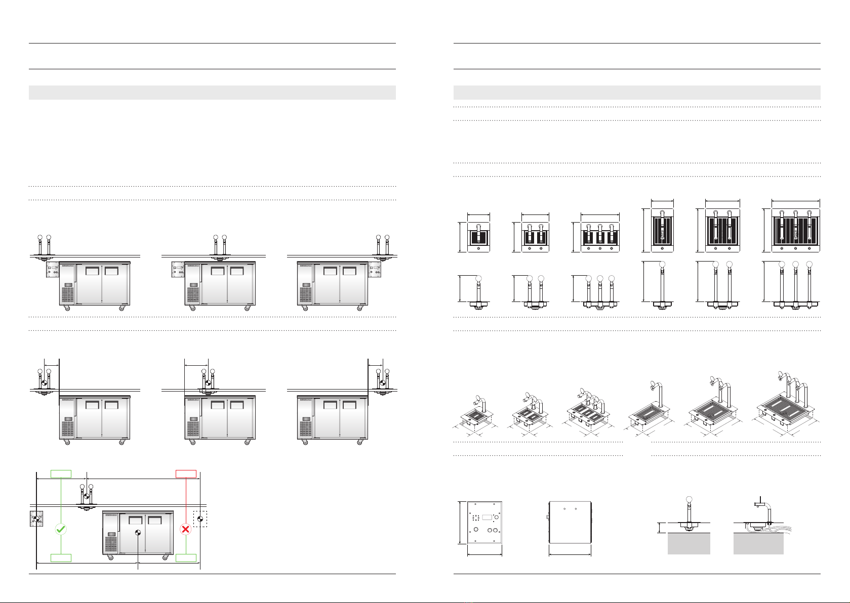
POSITIONING THE DISPENSER
There is no set distance that the Dispenser needs to be relative to the edge of the bench. Consider that the
height of the bench and how far the Dispenser is placed in from the edge of the bench will eect access to
the Dispenser for people of dierent heights.
DISPENSER DIMENSIONS
Single Double Triple Single Tall Double Tall Triple Tall
BENCH CUTOUT DIMENSIONS
A rectangular hole in the bench is required to set the dispenser into the bench surface. A ange runs around
the perimeter of the dispenser and covers the edge of the cut-out similar to a top mount sink.
Single Double Triple Single Tall Double Tall Triple Tall
CONTROL UNIT DIMENSIONS
If a triple tap dispenser has been chosen or 2 x
double tap dispensers are running from a single
chiller, 2 x Control Units will have been supplied.
UNDER BENCH CLEARANCE
Space is required below the Dispenser to allow
room for the dispenser drain. This is measured
from the TOP surface of the bench.
max
400
<400<400
PLANNING THE DISPENSE STATION
The modular design of Freepour allows for a variety of installation congurations to suit your dispense station
layout. When deciding where each of the three units will be located, consider how the machine will be used
in service, reloaded by sta and cleaned at the end of the day.
You should also consider whether the Chiller will be set on castors and therefore will be movable allowing
sta to clean under and behind it, or whether the Chiller will be on a plinth and will not be movable. Flexible
uid product lines and data cables run between the Chiller and the dispenser. It is important that these lines
are not kinked, squashed or disconnected when moving the Chiller or accessing adjacent equipment.
GENERAL LAYOUT
The Dispenser may be placed to the left, right or directly above the Chiller. The Control Unit is most
commonly mounted on the side of the Chiller that is closest to the Dispenser. It can however be set
elsewhere so long as the maximum permissible distances and clearances are observed.
MAXIMUM PERMISSIBLE DISTANCES
The maximum distance between the Dispenser and Chiller is 400mm, measured from the centre of the
Dispenser to the closest edge of the Chiller.
The maximum distance between the Dispenser and Control Unit is 1.2 meters. The Control Unit must be no
more than 2 meters from the Chiller measured from the centre of the Control Unit to the centre of the Chiller.
<1200
<2000
>1200
<2000 Dimensions shown in mm
2. Installation Overview & Procedure
Installation Overview & Procedure l98 l
1205
400
730
A750
B
195
Floor
Drain*
205
905
750 545 195
Floor
Drain*
A
B
205
730
1800
445
730
A750
B
195
Floor
Drain*
205
Fluid product
line location
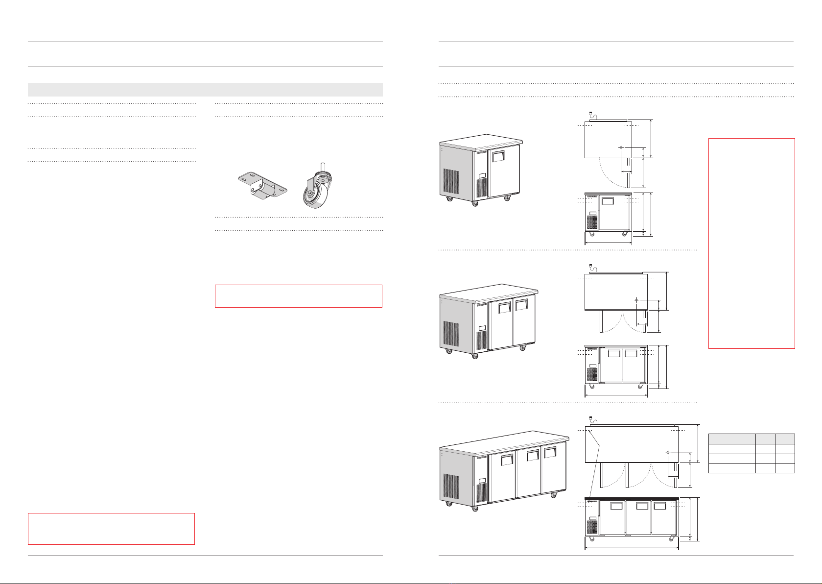
CHILLER DIMENSIONS
One Door Height Options
Two Door
Three Door
Roller Castors Standard Castors
Installation Overview & Procedure l1110 lInstallation Overview & Procedure
FREEPOUR CHILLER
OPERATING TEMPERATURE RANGE
The Chiller is designed to operate at 1°C to 4°C in
up to 38°C ambient.
LOCATING THE CABINET
Location
When positioning the cabinet, avoid direct sunlight
and warm draughts etc and areas where the
refrigeration unit could be exposed to water or
moisture. The cabinet must NOT be situated where
it is aected by warm or hot air from adjacent
equipment as this will compromise the airow and
performance of the cabinet.
The cabinet must be positioned on a level surface
for the doors to shut and seal correctly and to
prevent the condensate tray from overowing.
Allow adequate space for the doors to open fully,
including the compressor compartment door.
Ensure all packaging is removed from the cabinet.
Ventilation
Ensure there is always at least a 50mm gap around
the back and the refrigeration unit side of the
cabinet and that the hot refrigeration exhaust
air is not restricted and can easily ow out and
away from the front of the cabinet. Never store
cardboard cartons or other items in front of the
refrigeration unit. The ventilation slots on the
refrigeration unit front cover must be kept clear at
all times.
Normal operating conditions should not exceed
the operating temperature range.
Power Supply
The cabinet is supplied with a exible power
cord and plug which exits the rear of the cabinet.
Before nal positioning of the cabinet, uncoil the
power cord and connect to the power supply. For
convenience any surplus cord length may coiled
and xed to the rear of the cabinet compartment.
WARNING: Do NOT overload the power supply. See
the rating label inside the cabinet and also page 6
of this guide for power supply and current draw.
POSITIONING THE CABINET
Castors
The Chiller is usually delivered to site on standard
height castors. Short roller style castors can be
supplied by request and tted on site.
OPERATION
Automatic Start-Up
Connect the cabinet to the mains power supply
and check operation of the refrigeration unit and
electronic controller. Ensure the cabinet power
switch is turned on.
IMPORTANT: If the cabinet has been on its back,
leave for 30 minutes before running.
Power Switch
The cabinet is tted with a power switch, located
beside the electronic controller. Open the
compressor cabinet door to access the switch.
Refrigeration Unit
The compressor/condenser and evaporator
fans should all operate within two minutes from
the time the cabinet is plugged in. This may be
veried by listening for compressor switch-on and
checking for air movement inside the cabinet. The
compressor/condenser fan will switch o when the
cabinet internal air reaches a pre-set temperature.
Electronic Controller
When the cabinet is rst connected to the power
supply, the electronic controller will display the
current cabinet temperature. The compressor
symbol will come on after a few minutes, indicating
the compressor/condenser fan is operating.
To ensure ecient operation, the electronic
controller forces regular defrosts. During the
defrost cycle, the compressor/condenser fan
switches o and the evaporator fan stays on.
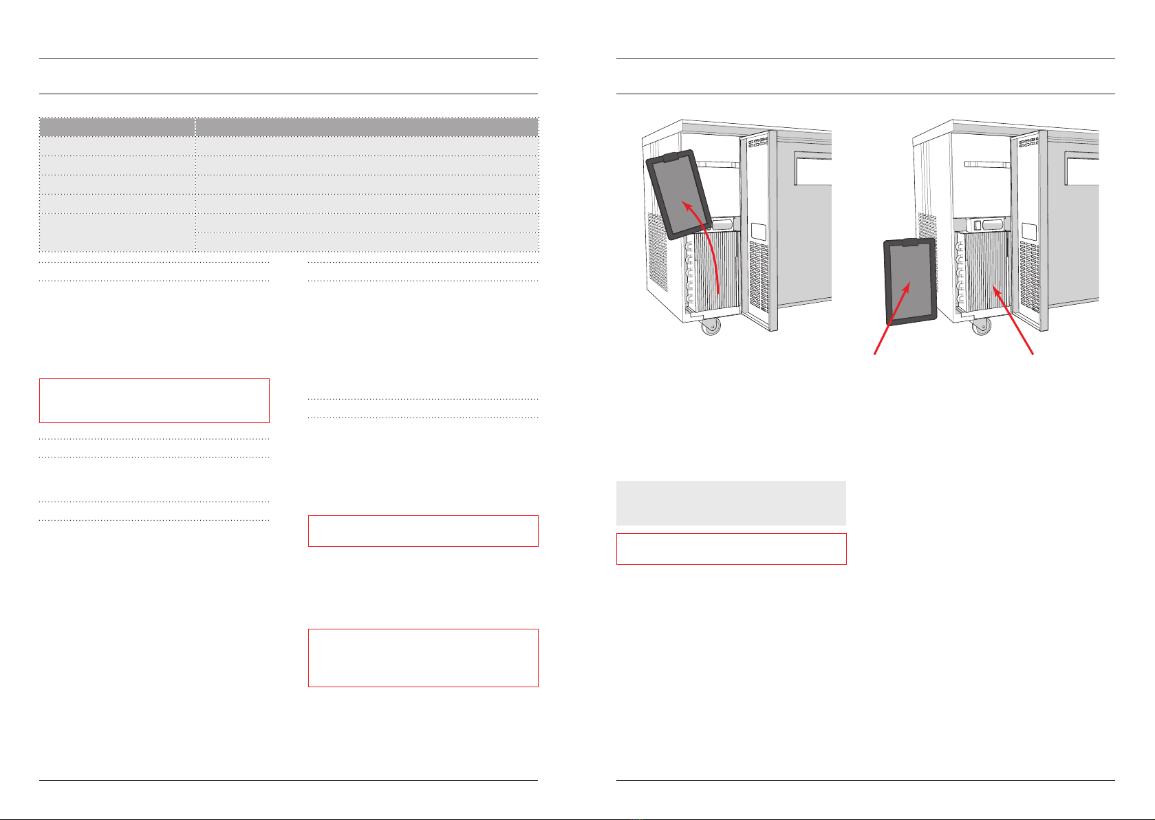
The Chiller can be installed on
castors or directly on a plinth.
IMPORTANT: We recommend
against plinth installations
because of the inherent
risk of uid tracking under
the Chiller and becoming
trapped between the Chiller
and plinth.
This risk is greater if a oor
pan style drain has not been
installed in the plinth.
If you install the Freepour
Chiller on a plinth we
recommend you discuss the
practicalities of installing a
oor pan style drain pan in
the plinth under the oor
drain* location with your
builder. If this is not practical
the drain plug can be
permanently xed in place.
See page 15: Step I.
*Not all Chillers are supplied
with a oor drain.
We oer two styles of
castors to accommodate
dierent bench heights. For
height options refer to the
dimensions labelled as A
and Bin the dimensioned
drawings and the table
below.
A B
Standard Castors 95 845
Roller Castors 30 780
Plinth NA 750
Dimensions are shown in
millimetres.

Note corresponding coloured labels
INSTALLATION PROCEDURE
Be aware that the system you are installing may dier from the example below. A major point of dierence is
that there may be 2 control units supplied. This is the case for example for dispensers with 3 taps, or systems
where 2 dispensers connect to a single chiller. The installation process for the second controller is the same as
shown below.
STEP A PLACE DISPENSER INTO THE HOLE IN THE BENCH
1. Uncoil the uid product lines and data cables;
2. Lower Dispenser into the hole in the bench.
NOTE: The Dispenser will be set in place with
silicone or similar sealant in Step G.
STEP B CONNECT DRAIN HOSE
1. Push the drain hose onto the barb connector
underneath the sink and attach hose clamp;
2. Route the drain hose to a drain and cut hose
to length.
IMPORTANT: For good drainage ensure adequate
fall and avoid sags in the hose. Ensure the end of
the drain hose cannot become submerged in the
drain.
STEP C MOUNT CONTROL UNIT AND CONNECT CONTROL TO PUMP CABLE
1. Mount the Control Unit on the Control Unit
mounting bracket;
2. Uncoil the Control to Pump cable from the
rear of the Chiller and connect to the rear of
the Control Unit;
IMPORTANT: To avoid malfunction ensure the
small catch on the male connector clips over the
retaining lug on the female connector.
3. Push the Chiller into place.
NOTE: Freepour generally ships with the Control
Unit mounting bracket and Control to Pump cable
set for a LHS installation. If the Control Unit is to
be set on the RHS of the Chiller or elsewhere the
Control Unit mounting bracket can be removed
from the Chiller and repositioned. The Control to
Pump cable can also be rerouted in the conduit on
the rear of the Chiller.
Installation Overview & Procedure l1312 lInstallation Overview & Procedure
STEP D CONNECT FLUID PRODUCT LINES TO CHILLER
1. Feed the blue protective sleeves over the uid
product lines. Push the sleeves rmly up to
the tting at the base of the tap. Observe the
stickers on the protective sleeves showing the
tap and Chiller ends of the sleeve;
2. Feed insulation over the uid product lines.
Fasten in place with cable ties at both ends;
3. Punch out the centre of the rubber openings
in the side of the Chiller (inside and outside)
and push the uid product lines through
the openings until the STOP sticker on
the protective sleeve contacts the rubber
opening. It can be helpful to wet the product
lines with water and dishwashing soap before
pushing them through the openings.
STEP E CONNECT FLUID PRODUCT LINES INSIDE CHILLER
To account for all Freepour variants, uid product
lines are supplied long and need to be cut before
connecting to the manifold inside the Chiller.
1. Determine the length for the uid product
lines inside the Chiller and cut them to length;
NOTE: The length of the uid product lines inside
the Chiller is correct when they are not too long
and risk being kinked inside the Chiller and not
too short making connection dicult.
2. Plug 'A' uid product line into the top
connector on the manifold and 'B' uid
product line into the lower connector.
NOTE: Ensure that the uid product lines are
pushed FULLY into the ttings in the side of the
manifold so this connection does not leak.
STEP F CONNECT DATA CABLES
1. Connect the data cables (mentioned in STEP
A) to the rear of the Control Unit.
IMPORTANT: Ensure the small catch on the male
connector clips over the retaining lug on the
female connector. If this catch does not engage,
the connector may slowly uncouple and cause the
machine to malfunction.
Control
to Pump
cable
Mounting
bracket
Drain hose
not sagging
Drain hose
correct length
Drain hose
sagging
Drain hose
too long
Tap A
coloured label
Tap B
coloured label
Coloured labels are used to identify all fluid and data connections.
Ensure you connect fluid lines and data cables into connectors
with corresponding coloured labels.
Cable tie
Tap B
coloured label Insulation
STOP sticker
on protective
sleeve
Protective sleeve
Fluid product line
Note corresponding
coloured labels
STEP G FIX DISPENSER IN PLACE
1. Prop the Dispenser 5 to 10mm above the
bench to create a gap between the sink
ange and the bench surface;
2. Apply silicone or a similar sealant to the
bench surface under the sink ange. Follow
sealant manufacturer guidelines to ensure the
bond is strong and will not leak;
3. Remove props and carefully lower the
Dispenser into place;
4. Clean o excess sealant and allow to cure.
STEP H COMMISSIONING FREEPOUR
1. Visually inspect all connections to ensure they
are sound and in the correct place;
2. Plug the Chiller into a power supply of 220-
240 Volt AC and switch on;
3. Plug the Control unit into a power supply of
220-240 Volt AC and switch on;
NOTE: So you do not need to use bladders to test
for leaks and correct operation, set the system up
as if you are about to run the cleaning routine. Do
not add chemical to the water. See page 19 for
instructions on setting up the cleaning routine.
4. Press and hold activation button for each tap
and watch the stream of water to see that it
eventually runs clear without bubbles.
NOTE: A persistent stream of bubbles in the water
being dispensed may indicate a leak is present
somewhere in the system. You may need to top up
the cleaning bottle a few times during this test.
STEP I ASSESS CHILLER DRAIN PLUG
Some Chillers have a oor drain and plug.
IMPORTANT: If uid cannot drain away or
be easily collected, the drain plug should be
permanently sealed in place with silicone so it
cannot be removed. This is especially important
where a Chiller has been installed on a plinth.
BEFORE FIRST SERVICE
Run the Cleaning Routine and inspect for normal
operation. See page 19 for instructions on how to
run the cleaning routine.
OPTIONAL PROCEDURES
For the majority of applications the default
software settings will not need to be changed.
The two exceptions to this are:
1. Dose Time
This can be used, for example, to set a
recommended serve size or to discourage
excessive dispensing.
2. Flow Rate
This may be changed, for example, to slow
the rate of dispense into an unusual shaped
vessel to reduce the chance of overlling.
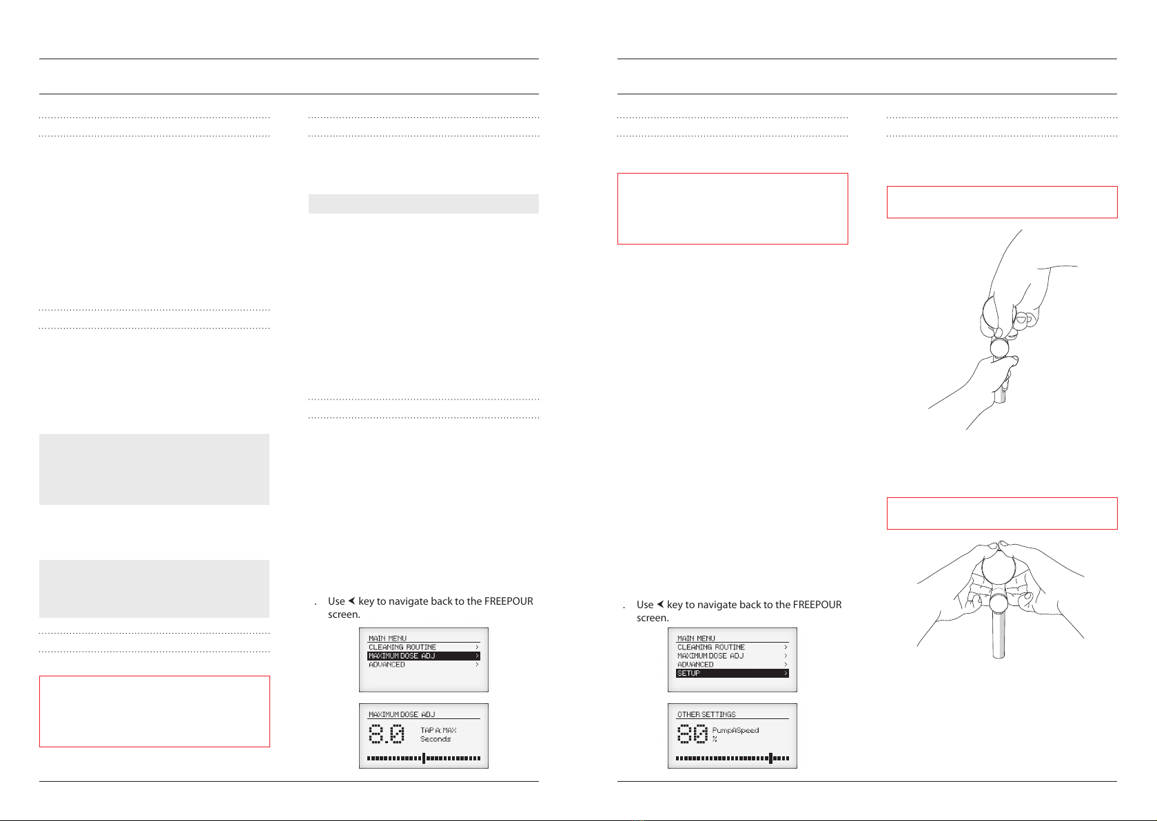
CHANGING THE DOSE TIME
Use the interface on the Control Unit to change
the Dose Time:
1. Use keys to navigate through MENU /
MAXIMUM DOSE ADJ to enter into the
MAXIMUM DOSE ADJ menu;
2. Use the adjustment dial to change the Dose
Time (in seconds) for Tap A;
3. Use key to navigate to Tap B;
4. Use the adjustment dial to change the Dose
Time (in seconds) for Tap B;
5. Use key to navigate back to the FREEPOUR
screen.
Installation Overview & Procedure l1514 lInstallation Overview & Procedure
CHANGING THE FLOW RATE
Flow Rate is in a hidden menu to help ensure it is
not changed by accident.
WARNING: The hidden SETUP menu contains
many essential system settings. We do not
recommend changing any settings in the hidden
SETUP menu unless you are sure you understand
the purpose of the setting and likely consequence.
To access the hidden SETUP menu:
1. Switch Freepour to MANUAL using the ON-
MANUAL BACKUP switch on the Control Unit;
2. Press and hold the UP and DOWN navigation
keys and switch Freepour to the ON position;
3. Wait to see DEBUG MODE appear briey on
the screen, then release the UP and DOWN
navigation keys.
To change the Flow Rate:
1. Use keys to navigate through MENU /
SETUP / OTHER SETTINGS. Press to enter
into the OTHER SETTINGS menu;
2. Use key to navigate to pump A speed
adjustment screen;
3. Use the adjustment dial to change the pump
speed (as a % between 0 and 100) for Tap A;
4. Use key to navigate to pump B speed
adjustment screen;
5. Use the adjustment dial to change the pump
speed (as a % between 0 and 100) for Tap B;
6. Use key to navigate back to the FREEPOUR
screen.
CHANGING THE PRODUCT TYPE BADGES
The badge holder can be removed from the taps
by rmly pulling the badge holder upward using
the technique shown below.
WARNING: Support the tap when removing the
badge holder otherwise the tap may be damaged.
The badge holder can be xed to the taps by
inserting the badge holder into the slot in the tap
and rmly pushing the badge holder down using
the technique shown below.
WARNING: Support the tap when replacing the
badge holder otherwise the tap may be damaged.
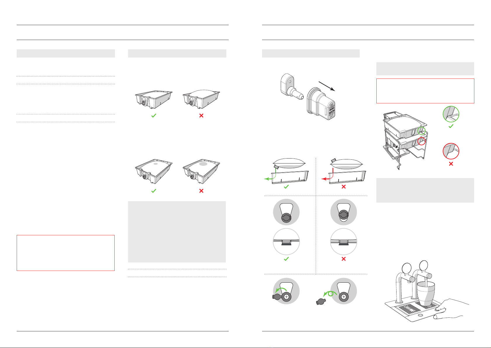
Cap correctly
clipped in
Cap NOT correctly
clipped in
Flip centre of
cap open
Twist to remove
centre completly
Cap face down Cap face up
Tray end past
rack end
Tray NOT past
rack end
3. Operating Freepour
16 lOperating Freepour l17
DAILY SETUP PROCEDURE
1. Remove red caps from the black connectors
inside the Chiller;
2. Remove, empty and clean the internal drip
tray(s). Replace the drip tray(s);
3. Load bladders into trays and remove the
centre of the cap;
4. Load the trays into the Chiller, starting at the
top position;
NOTE: Push the tray in quickly so milk does not
leak from the cap during connection.
IMPORTANT: Ensure the tray is rmly pushed past
the rack ends. If the tray is not pushed all the way
in, a bladder may not be connected properly and
may leak.
NOTE: If there are partially used bladders from
the day before, load these into the top positions
so they are used before full bladders loaded in the
lower positions.
5. Inspect the internal drip trays for evidence of
leaks caused by poorly connected bladders;
6. Turn Freepour ON at the Control Unit;
7. Activate a dispense cycle on all taps to prime
the system ready for use. Priming is complete
when a constant stream of uid product is
being dispensed.
OPERATING MODES
Use the ON-MANUAL BACKUP switch to select
between the following 2 operating modes:
ON
When the ON-MANUAL BACKUP switch is pressed
in the dispensing system is ON and all automatic
features, such as dispensing, automatic reverse
ow and running the cleaning routine, are active.
MANUAL BACKUP
When the ON-MANUAL BACKUP switch is not
pressed in, the unit is in STANDBY mode and all
automatic dosing and programming features are
not active.
In the event that the electronics are
malfunctioning, Freepour can still dispense milk as
long as the internal power supply and pumps are
still active. No dosing and programming features
are active in this mode.
Manual dispensing:
ON-MANUAL BACKUP switch must be in the
MANUAL BACKUP position (not pressed in).
1. Place a vessel under a tap;
2. Press and hold the RUN LEFT TAP or RUN
RIGHT TAP button on the Control Unit to
dispense product. Release the button to stop
dispensing.
IMPORTANT: Switching the ON-MANUAL
BACKUP switch to the MANUAL BACKUP position
does not cut the power o to the Control Unit. To
cut power o to the Control Unit, turn the power
o at the wall socket and remove the Control Unit
plug from the wall socket.
BLADDERS
To work well in Freepour, bladders must:
1. Hold exactly 10L of uid product
If overlled bladders are forced into the
Chiller, they may leak;
2. Contain as little air as possible
If a bladder contains too much air, dosing
becomes inconsistent and bubbly as each
bladder empties.
NOTE: If a bladder contains a large air bubble, it
is possible to manually bleed the air out before
loading the bladder into the Chiller.
To do this:
1. Place the bladder on a at surface with the
cap facing up and remove the centre of the
cap;
2. With the cap held higher than the bladder,
use a teaspoon to slightly open the valve as
you slowly push down on the bag.
HANDLING BLADDERS
Bladders are tougher than they appear but may
develop a leak if handled or stored incorrectly.
When handling bladders, always:
1. Carry a bladder using 2 hands;
2. Do not carry a bladder by the cap;
3. Be careful of sharp objects or edges; and
4. Be careful not to pinch bladder between tray
and racks when loading.
Small air bubble Large air bubble
Bladder fits well
in tray
Bladder bulges higher
than the top of the tray
DISPENSING PRODUCT
ON-MANUAL BACKUP switch must be in the ON
position (pressed in).
1. Place a vessel under the tap outlet;
2. Press and hold the corresponding activation
button to begin dispensing;
3. Release the button to stop dispensing.
NOTE: Dispensing will automatically stop if the
button is pressed for a time that exceeds the Dose
Time settings. The default Dose Time settings are:
• Standard height Dispenser = 8 seconds
• Tall Dispenser = 12.5 seconds
RELOADING DURING SERVICE
1. Wait for more than 10 seconds after the last
dispense cycle before removing a bladder;
NOTE: By default the Automatic Reverse Flow
feature activates 10 seconds after the last
dispense cycle.
2. Remove a tray holding an empty bladder.
Remove and discard the bladder;
3. Load a new bladder into the tray and load the
tray into the Chiller.
RELOADING A 'CONNECT 4' CHILLER
In a 'Connect 4' Chiller, the top two bladders are
usually dedicated to one uid product type and
the lower two bladders are dedicated to a second
uid bladder type.
Both bladders of a uid product type empty at
roughly the same rate.
RELOADING A 'CONNECT 8' CHILLER
In a 'Connect 8' Chiller, the four LHS bladders are
dedicated to one uid product type and the four
RHS bladders are dedicated to a second uid
bladder type.
The bladders empty from the top position to the
lowest position in an overlapping sequence.
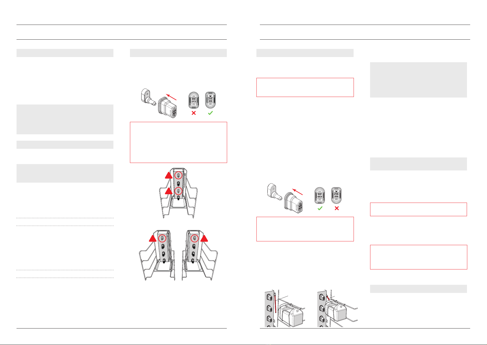
BLANKING
Freepour can be run on as few as one bag of each
product type. A red cap must be placed over
unused connectors in the BLANK orientation
otherwise the machine will suck air in through the
uncovered connectors which disrupts dispensing.
IMPORTANT: When in dispensing mode, the
connectors highlighted below should always
have a bladder connected. Never place a red cap
on these connectors in the BLANK orientation
otherwise uid product will be sprayed into the
Chiller following each dispense cycle and during
the automatic reverse ow cycle.
Operating Freepour - After Service
Operating Freepour l19
Operating Freepour - During Service
18 lOperating Freepour
DAILY CLEANING ROUTINE
The milk and juice systems are independently
cleaned using dierent cleaning chemicals. See
page 5 for information on cleaning chemicals.
IMPORTANT: Follow the procedure below for the
milk system using Daily Milk Line Cleaner and also
for the juice system using Daily Juice Line Cleaner.
1. Enter the cleaning routine screen via the
Control Unit: MENU > CLEANING ROUTINE;
2. Remove trays with empty bladders. Discard
empty bladders and wash the trays;
3. Remove trays with partially full bladders. To
prevent bladders leaking from the cap, ip
each bladder so the caps point upward;
4. Use a soft cloth and food-safe cleaner to clean
around the base of each black connector;
5. Place a red cap on all black connectors.
Ensure the red cap is pushed rmly into place
and the rounded edge is at the top;
IMPORTANT: If you have used a red cap in the
BLANK orientation you must remove the cap and
ip it around to the CLEAN orientation to ensure
the entire dispensing system is cleaned correctly.
6. Mix 100ml of the correct Freepour Line
Cleaner with 2L of warm water (40-50) in the
corresponding Freepour cleaning bottle;
7. Hook the cleaning bottle on the rail inside
the Chiller and engage the cleaning tube in
the hole in the lid. Slide the cleaning bottle
forward as far as it will go and close the door;
8. Initiate the cleaning routine via the Control
Unit: ACTIVATE >;
NOTE: The cleaning routine runs unassisted for
around 15 minutes. During this time, the lights
in the activation buttons ash and the taps will
periodically dispense a short burst of cleaning
solution. A progress bar on the Control Unit screen
shows the progress of the cleaning routine.
9. At the 15 minute mark, the lights in the
buttons stay on and ACTIVATE WATER FLUSH?
is displayed on the Control Unit screen.
Remove the cleaning bottle and empty
remaining cleaning solution. Rinse and ll the
cleaning bottle with 2L of cold water. Load as
directed in Step 7;
10. Activate the water ush via the Control Unit:
ACTIVATE WATER FLUSH? > YES;
NOTE: The water ush runs unassisted for around
30 seconds.
11. Turn Freepour to MANUAL BACKUP on the
Control Unit;
12. Use a soft cloth and food-safe cleaner to clean
around each tap outlet;
IMPORTANT: Do not use a bottle brush to clean
inside the Freepour tap outlets.
13. Remove and rinse cleaning bottle and drip
trays. Clean internal fridge surfaces and
external surfaces of the Dispenser. Replace
drip trays.
IMPORTANT: If your Chiller has a oor drain
ensure that uid can be easily collected or can
easily drain away when the drain plug is removed.
If in doubt, do not remove the drain plug.
Cleaning is now complete!
LEAVING FREEPOUR OVERNIGHT
1. Leave red caps on connectors after the
cleaning routine is complete;
2. Ensure all partially used bladders have been
ipped on their backs to prevent them from
leaking into the Chiller overnight.
!
!
‘Connect 4’ Chiller
‘Connect 8’ Chiller
!!
Cleaning
tube
Engage
cleaning tube
4. Freepour Chiller
Freepour Chiller l2120 l
FREEPOUR CHILLER
Changing settings that relate to the operation of
the Chiller is performed through the electronic
controller.
The electronic controller is visible through a cut
out in the front panel. It controls and displays
the cabinet interior temperature and signals
temperature alarms. It uses temperature probes
around dierent areas of the refrigeration system
to collect data and to run the cabinet accordingly.
The electronic controller is pre-programmed
and requires no initial setup or additional
programming. We do not recommend that
the settings be changed unless it is absolutely
necessary.
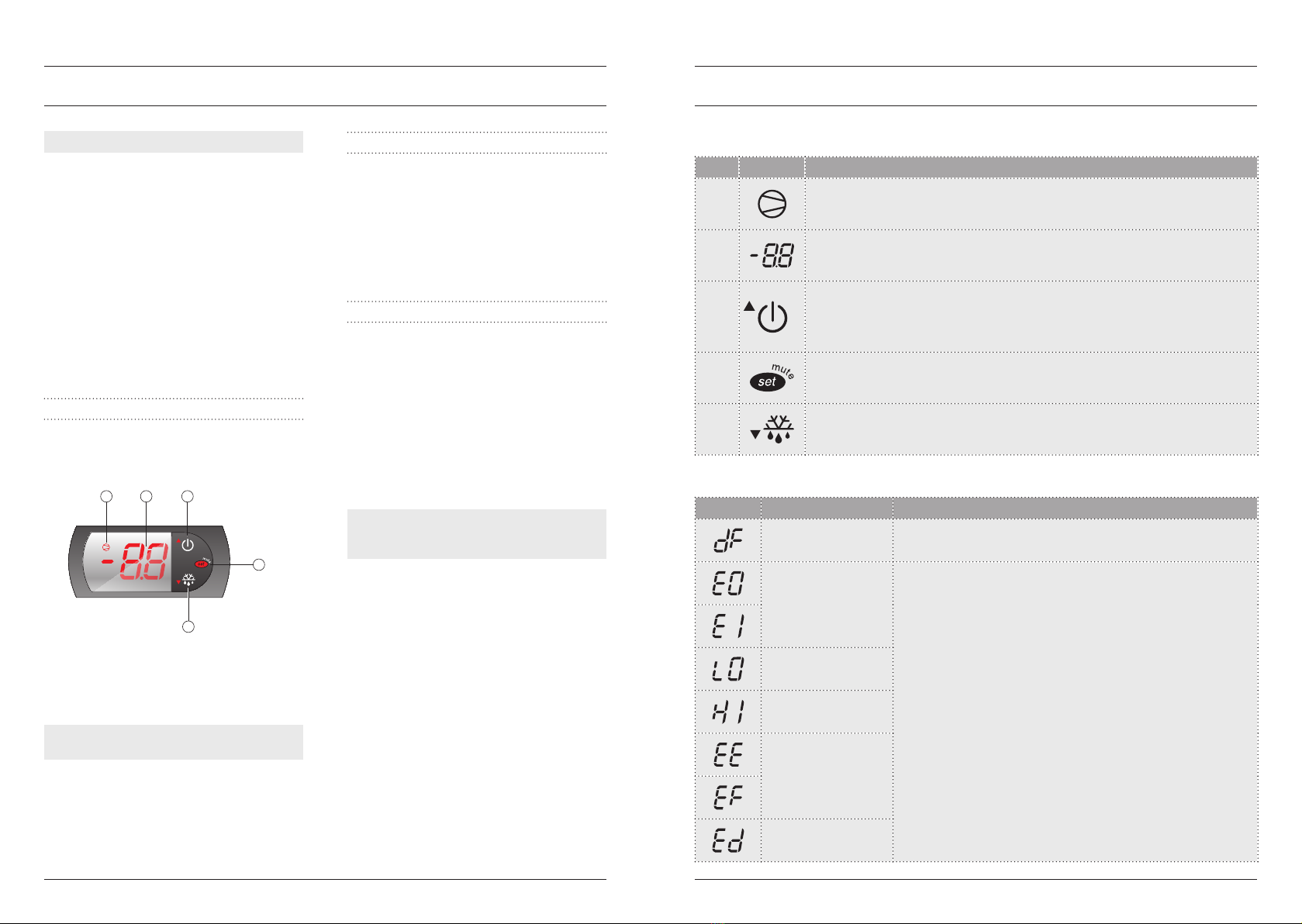
CAREL EASY ELECTRONIC CONTROLLER
Because the electronic controller plays such an
important role, it’s helpful to know the parts of
the faceplate you may use.
1. Compressor Indicator
2. Display
3. Stand-by (up) button
4. Mute (set) button
5. Manual defrost button
NOTE: See the table on page 21 for the function of
each item above.
STANDBY MODE
Press and hold the stand-by button for three
seconds to turn stand-by mode on or o. When
stand-by mode is on, the controller display will
alternate between the cabinet temperature and
Of, and the compressor, fans and alarms are
disabled.
The interior light is still activated by the door
switch and will come on when a door is opened.
TEMPERATURE SETPOINT
The temperature setpoint is factory set and can be
adjusted if necessary.
We do not recommend that the setpoint be
changed unless it is absolutely necessary, and
then only by small increments at a time.
To view and adjust the temperature setpoint:
1. Press and hold the set button until the
controller display shows SEt followed by a
temperature value. The temperature value is
the current setpoint.
NOTE: If PS appears on the display, the set button
has been held for to long. Release it, then press the
set button twice to restart the procedure.
2. Press the up and down buttons to adjust the
value to the required setpoint.
3. Press the set button again to store the new
setpoint value.
Carel Easy - Icons and Functions
Item Icon Function
1Compressor indicator
ON when the compressor and condenser fan starts.
Flashes when activation of the compressor is temporarily delayed.
2Display
Shows the cabinet temperature.
Flashes when the door is open.
3Stand-by (up) button
Turns stand-by mode on and o.
To scroll settings up (in program mode).
Note: This is not an isolation switch.
4Mute (set) button
Mutes the audible alarm (buzzer) and deactivates the alarm relay, and used in
program mode.
5Manual defrost button
Press for more than 5 seconds to initiate manual defrost.
To scroll settings down (in program mode).
Carel Easy - Messages and Alarms
Code Alarm Action
Defrost cycle in
progress message
Cabinet is running correctly.
Message will stop displaying once the defrost cycle is complete.
Temperature sensor
fault alarm
Reset alarm by unplugging the cabinet from the power supply
for one minute, then reconnect.
If alarm persists, arrange a service call.
Product low
temperature alarm
Product high
temperature alarm
Parameter error alarm
Defrost error alarm
1 2 3
5
4
5. Maintenance
Maintenance l2322 l
Item Frequency
Surface cleaning Daily
Flush and Sanitise milk lines Daily
Deep Clean 6 monthly intervals
Clean Chiller condenser lter At least once per week
Clean Chiller condenser coil Brush clean: Once a month
Blow clean: 6 monthly intervals
CLEANING
Stainless Steel surfaces are easily scratched
by poor cleaning practices. Proper cleaning of
stainless steel requires soft cloths. Never use
scourers, steel pads, wire brushes or scrapers.
Wipe both the interior and exterior of the chiller
cabinet with a damp cloth.
IMPORTANT: Ensure the cabinet is unplugged
from the mains power supply before cleaning the
Chiller cabinet with water.
FLUSH AND SANITISE MILK LINES
Refer to page 19 for instructions on how to run
the Daily Cleaning Routine.
DEEP CLEAN
The Deep Clean procedure is performed by a
qualied service technician.
Contact Six Simple Machines to arrange for a Six
Simple Machines authorised service agent to
perform the Deep Clean.
CONDENSER FILTER
The condenser lter must be cleaned at least
once every week. Failure to do so will result
in inecient cooling performance, increased
electricity consumption and damage to the
compressor or other refrigeration components.
See page 23 for instructions on how to clean the
condenser lter.
CONDENSER COIL
Fine dust can pass through the lter and collect
on the condenser coil ns. The ns should be
inspected and cleaned once a month or more
frequently if required.
See page 23 for instructions on how to clean the
condenser coil.
IMPORTANT: Unplug the cabinet from the power
supply before cleaning the condenser coil.
Over time dust may accumulate within the
condenser coil that cannot be easily removed
with a brush. The condenser coil should be
professionally cleaned by a qualied refrigeration
technician every six months.
IMPORTANT: Failure of any refrigeration
component caused by poor cleaning of the dust
lter or condenser coil is not covered by the Chiller
warranty.
Cleaning the condenser lter
1. Open the compressor compartment door to
gain access to the condenser lter;
2. Remove the condenser lter by sliding it up.
Remove all dust and u from the lter using
a brush or a vacuum cleaner;
NOTE: If cleaning the condenser lter with a brush
or vacuum cleaner is not sucient, the lter may
be rinsed or washed with water.
IMPORTANT: If the lter has been rinsed with
water, ensure it is fully dry before retting it.
3. Ret the condenser lter, compressor
compartment door and reconnect the cabinet
to the power supply.
Cleaning the condenser coil
1. Isolate the cabinet from the power supply by
unplugging it from the wall;
2. Open the compressor compartment door to
gain access to the condenser lter and coil;
3. Remove the condenser lter by sliding it up.
Remove all dust and u from the lter;
4. Brush the condenser coil in the directions of
the ns to remove all dust and u;
5. Ret the condenser lter, compressor
compartment door and reconnect the cabinet
to the power supply.
Remove condenser filter Condenser filter Condenser coil
Troubleshooting l25
6. Troubleshooting
24 l
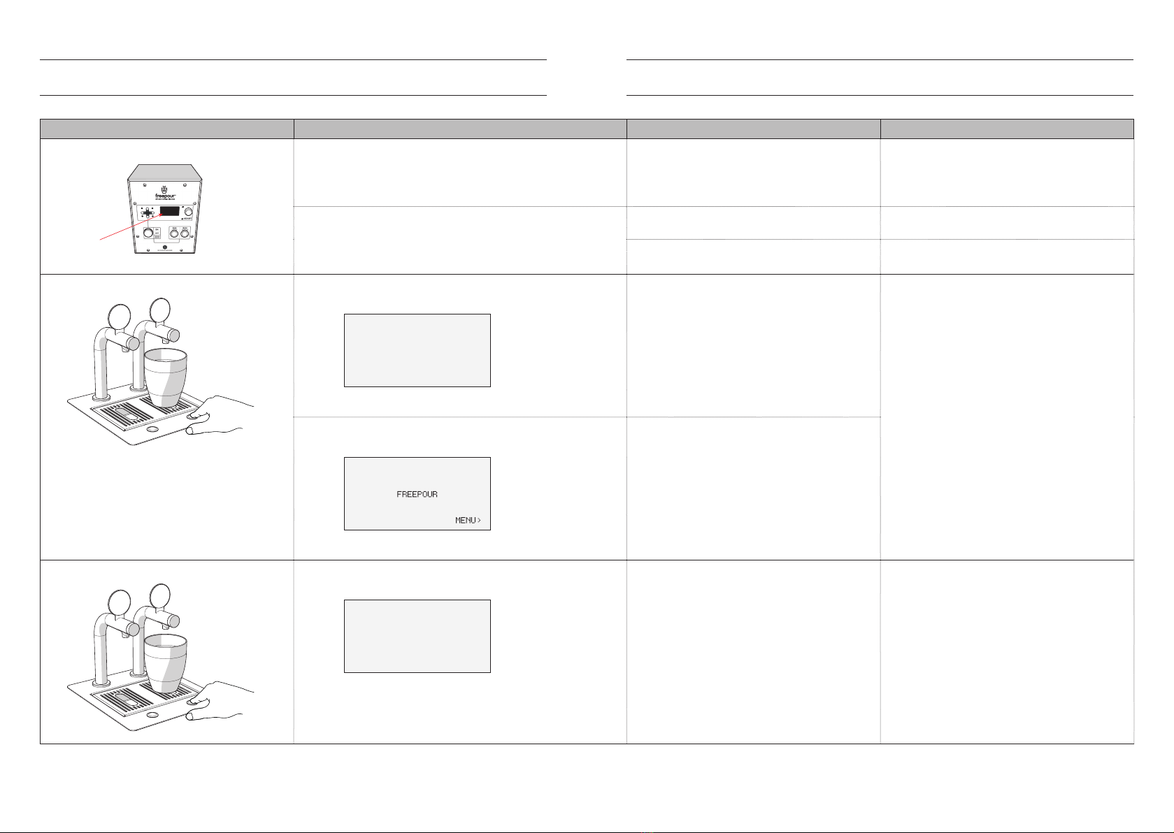
Problem Troubleshooting Tips Possible Cause Solution
The system does not turn on
SIX
SIMPLE
MACHINES
Blank screen
Check that the Control Unit is plugged into a power
outlet and the outlet is switched on; and
Conrm the outlet is working by plugging in another
appliance.
The Control Unit is not receiving power. Connect power cord to a functioning outlet and
turn on.
Switch to MANUAL BACKUP and press and hold RUN
LEFT TAP and RUN RIGHT TAP; and
Listen for the sound of the pumps running and/see
that the tap(s) are dispensing.
If pumps run:
• The Freepour electronics may have failed.
Run the system in MANUAL BACKUP mode and call
a service technician.
If pumps do not run:
• The Freepour power supply may have failed.
Call a service technician.
Dispensing cannot be activated on one or both taps Check Control Unit screen to see if there is the NO
CURRENT error message being shown.
NO CURRENT ON HEAD A
CHECK PUMP FUSE!
PRESS < TO CANCEL
Error shown on screen
If the NO CURRENT error is displayed on screen:
• The pump cable may have become
disconnected;
• The circuit breaker(s) may have tripped;
• A pump may be jammed; or
• The pump(s) may have failed.
Reconnect pump cable and press key on the
Control Unit to clear the error;
Reconnect data cable(s) and press key on the
Control Unit to clear the error;
Push circuit breaker in and press key on the
Control Unit to clear error; or
Call a service technician.
Check Control Unit screen to see if there is an error
message being shown.
No error shown on screen
If there are no errors displayed on screen but the
screen is on:
• The data cable(s) may have become
disconnected; or
• The pump(s) may have failed.
Dispensing cannot be activated on either tap Check Control Unit screen to see if there is the
OVERCURRENT error message being shown.
OVERCURRENT ON HEAD A
PRESS < TO CANCEL
Error shown on screen
If the OVERCURRENT error is being displayed on
screen:
• A uid product line may be kinked or blocked;
or
• A pump may be jammed.
Inspect the uid product lines for kinks and un-kink
the aected line.
If no kinks can be found or a kink has weakened the
uid product line, call a service technician.
Troubleshooting l2726 lTroubleshooting
Problem Troubleshooting Tips Possible Cause Solution
Audible 'gurgling' sound and no product is
dispensed or product being dispensed is unusually
bubbly
Gurgle Bubbly
and/or
spitting
Gurgle
Gurgle
Check to see that red caps are being used correctly
(see: BLANKING page 18 and ACTIVATING THE
CLEANING ROUTINE page 19).
The red caps may be upside down or not properly
pushed onto the black connector(s) inside the
Chiller.
Follow instructions on pages 18 and 19.
Check to see that bladders are loaded correctly. Bladders may not be connected correctly. Follow instructions on page 17.
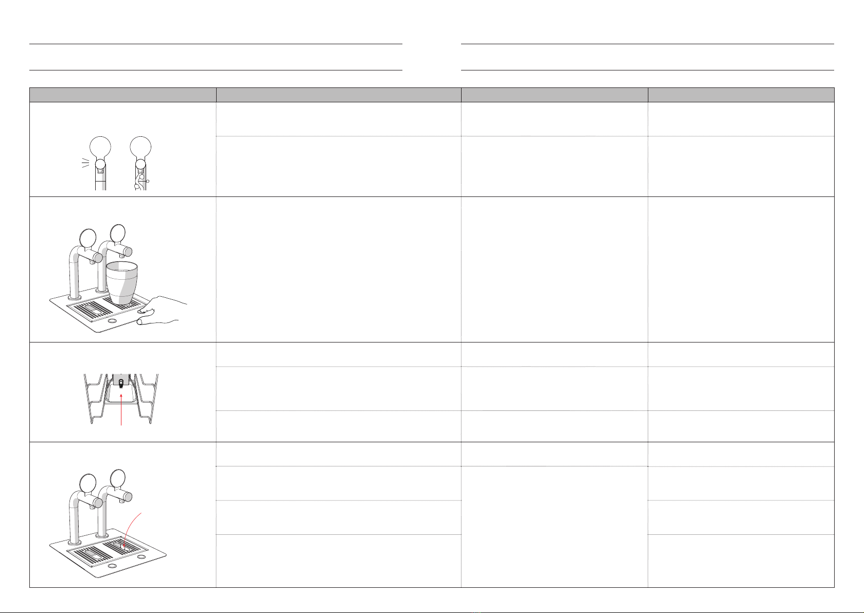
The dispense cycle is automatically stopping before
the activation button is released
Check to see the Dose Time settings:
• Use keys to navigate through MENU /
MAXIMUM DOSE ADJ to enter into the
MAXIMUM DOSE ADJ menu; and
• Check Dose Time settings.
The Dose Time may have been set too low for the
desired application.
Follow instructions on pages 14 to change the Dose
Time(s).
There is an unusually large volume of uid product
in the drip tray or bottom of the Chiller at the end of
service
Product in drip tray
Check to see that bladders are being loaded
correctly.
If trays are pushed into the Chiller too slowly, they
will leak from the cap as they are connecting.
Push the trays in quickly when loading a new
bladder (see page 17).
Make sure that the red caps are not being used in the
BLANK orientation on the connectors where this is
not permitted.
If the red caps are being used to in the BLANK
orientation on certain connectors in the Chiller,
small amounts of milk will spray into the Chiller
after each dose and Automatic Reverse Flow cycle.
Make sure you understand where you can and
cannot use the red caps in the BLANK orientation
(see: BLANKING page 18).
Make sure you understand how the Automatic
Reverse Flow feature works.
Poor understanding of the Automatic Reverse Flow
feature may be the cause.
Read the Automatic Reverse Flow section of the
user manual (see pages 7 and 18).
The sink is not draining or is draining slowly
and/or there is uid product on the oor
Sink not draining
Check that the Dispenser drain and oor drain are
not blocked.
The drain hose running between the Dispenser
drain and oor drain may be blocked.
Check that the Dispenser drain and oor drain are
not blocked.
Ensure drain hose has been correctly attached to
the barb tting on the drain and that the drain is not
loose in the sink.
The drain hose may have been poorly installed or
may have become dislodged.
Ensure the drain hose and drain are properly
installed (see page 12 for correct installation).
Check that the drain hose is not sagging or kinked
and has adequate fall from the Dispenser sink to the
cafe drain.
Ensure the drain hose is as straight as possible and
is angled downward all the way to the cafe drain
(see page 12 for correct installation).
Check that the end of the drain hose is not
submerged in the cafe drain.
Pull the end of the drain hose up out of the drain
and cut it shorter so it cannot become submerged
(see page 12 for correct installation).
At Six Simple Machines we are always looking for ways to improve our products.
The illustrations in this guide may differ slightly from the actual product.
Made in Australia
D00142 A05 l © 2020 SIX SIMPLE MACHINES Pty Ltd
This manual suits for next models
3
Table of contents
Popular Dispenser manuals by other brands

BOWMAN
BOWMAN CL003-0111 manual

SIKA
SIKA Power Cure operating instructions

Silver King
Silver King Majestic SK12MAJ Technical manual and replacement parts list

Franke
Franke F3Dn Twin Service manual

HURAKAN
HURAKAN HKN-MT1 manual

STIEBEL ELTRON
STIEBEL ELTRON UltraHot Plus Operation and installation instructions


