6
Impiego
Alloggiamento del cilindro di chiu-
sura con contatto a chiave a due
livelli per alloggiare un semicilindro
prolato predisposto a cura del
cliente secondo la norma DIN18252
con lunghezza totale di circa40mm.
Tensione elettrica
Gli interventi di installazione, mon-
taggio e assistenza agli apparecchi
elettrici devono essere eseguiti esclu-
sivamente da elettricisti specializzati.
Montaggio e installazione
Per inserire il cilindro di chiusura nel
relativo alloggiamento è necessario
innanzitutto aprire dal retro l’unità
funzionale.
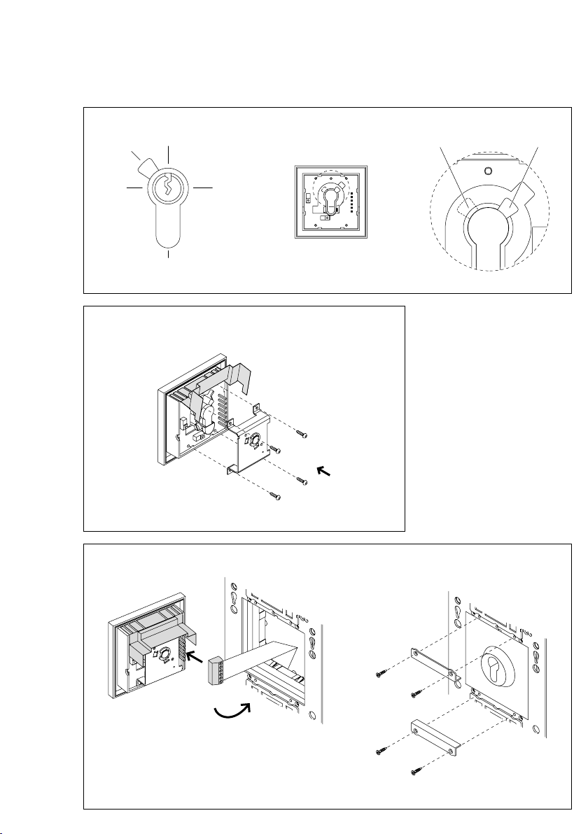
1 Circuito stampato di collega-
mento
con schema di principio (La posi-
zione di contatto contrassegnata
corrisponde alla posizione di riposo a
chiave non azionata)
Inserire il cilindro di chiusura
2 Prelevare il pannello di comando,
consultare l’opuscolo informativo sul
prodotto relativo al posto esterno.
3 Svitare l’alloggiamento del
cilindro di chiusura sul pannello di
montaggio, staccarlo dal pannello
di montaggio, quindi scollegare il
connettore.
4 Sbloccare la copertura “a” e sol-
levarla.
5Svitare le viti di ssaggio “c” sul
lato posteriore, rimuovere il mecca-
nismo di comando “b” del pannello
frontale e depositarlo a lato.
6 Inserire il semi-cilindro prolato
e ssarlo con la vite di bloccaggio.
Prestare attenzione alla posizione
dell’ingegno della serratura!
7 Posizionare la crocetta di chiusura
nella posizione voluta (Io II) girando
la chiave.
Italiano
Posizione “I”: crocetta di chiusura
“315°” condotta nella forcella di
comando. La chiave può essere
estratta solo se non è stato azionato
alcun contatto.
Posizione “II”: crocetta di chiusura
“45°” inserita a fianco della forcella
d’innesto. La chiave può essere
estratta solo se è stato azionato uno
dei due contatti.
8 Applicare e avvitare il meccanismo
di comando sul retro del frontalino.
9 Collegare il cilindro serratura,
inserire e ssare al pannello di mon-
taggio.
10 Eseguire un controllo del funzio-
namento
11 Applicare il pannello di comando
sul pannello di montaggio e bloccare
con la chiave di montaggio.
Dati tecnici
Tipo di contatto: Contatto normal-
mente aperto 24V, 2A
Tipo di protezione: IP54
Temperatura ambiente:
da–20°Ca+55°C
Toepassing
Sluitcilinder-opname met tweec-
ferig toetscontact voor de opname
van een lokale proel-halfcilinder
volgens DIN18252 met ca. 40mm
totale lengte.
Elektrische spanning
Inbouw, montage en onderhouds-
werkzaamheden aan elektrische
apparaten mogen uitsluitend door
een elektro-vakman worden uitge-
voerd.
Montage en installatie
Om een sluitcilinder in de sluitci-
linder-opname te plaatsen, dient de
functie-eenheid allereerst aan de
achterzde te worden geopend.
1 Aansluitprintplaat
met principeschema (getekende
contactpositie komt overeen met
de rustpositie b een niet gedrukte
sleutel)
Sluitcilinder plaatsen
2 Bedieningsplaat afnemen, zie pro-
ductinformatie over het deurstation.
3 Sluitcilinder-opname van de
montageplaat los schroeven, van de
montageplaat afnemen en aansluit-
stekker los trekken.
4 Maak de beschermkap „a“ los en
klap ze omhoog.
5Bevestigingsschroeven „c“ op de
achterzde losdraaien, de schakel-
mechanisme „b“ van de frontplaat
afnemen en opz leggen.
6 Proel-halfcilinder plaatsen en met
bevestigingsschroef xeren. Let op
de sluitbaardpositie!
7 Zet de slotbaard in de gewenste
stand (Iof II) door de sleutel om te
draaien.
Stand „I”: slotbaard „315°” in de
schakelvork geleid. De sleutel kan
alleen worden weggenomen, als
geen van de contacten in werking
is gezet.
Nederlands