Stübbe SP 820 Series User manual

Water-jet pump
Operating manual Series SP 820
Version BA-2023.09.27 EN
Print-No. 302 535
TR MA DE Rev001
STÜBBE GmbH & Co. KG
Hollwieser Straße 5
32602 Vlotho
Germany
Tel: +49 (0) 5733-799-0
Fax: +49 (0) 5733-799-5000
E-mail: co[email protected]
Internet: www.stuebbe.com
Subject to technical modifications.
Read carefully before use.
Save for future use.

Table of contents
Table of contents
1 About this document ............................... 3
1.1 Target groups ................................. 3
1.2 Other applicable documents ................ 3
1.3 Warnings and symbols ....................... 3
2 Safety instructions ................................. 4
2.1 Intended use .................................. 4
2.2 General safety instructions .................. 4
2.2.1 Obligations of the operating company ...... 4
2.2.2 Obligations of personnel ..................... 4
2.3 Hazardous media ............................ 4
3 Layout and Function ............................... 5
3.1 Marking ....................................... 5
3.1.1 Name plate ................................... 5
3.2 Description .................................... 5
3.2.1 Features ...................................... 5
3.2.2 Function ....................................... 5
3.3 Assembly ..................................... 5
4 Transport, Storage and Disposal ................. 6
4.1 Unpacking and inspection on delivery ...... 6
4.2 Transportation ................................ 6
4.3 Storage ....................................... 6
4.4 Disposal ....................................... 6
5 Installation and connection ....................... 7
5.1 Preparations for installation ................. 7
5.2 Planning pipelines ............................ 7
5.3 Design the layout of the fitting ............... 7
5.4 Install the fitting ............................... 7
5.4.1 Connection with flange ...................... 7
5.4.2 Connection with sockets, nozzles or female
threads ........................................ 8
5.5 Performing the hydrostatic test .............. 8
6Operation ............................................ 8
6.1 Commissioning ............................... 8
7 Maintenance ......................................... 9
7.1 Servicing ...................................... 9
7.2 Maintenance .................................. 9
7.2.1 Removing fitting .............................. 9
7.2.2 Disassemble and reassemble the
nozzle ......................................... 9
7.3 Replacement parts and return .............. 9
8 Troubleshooting .................................... 10
9 Appendix ............................................. 11
9.1 Technical specifications ...................... 11
9.2 Replacement parts ........................... 11
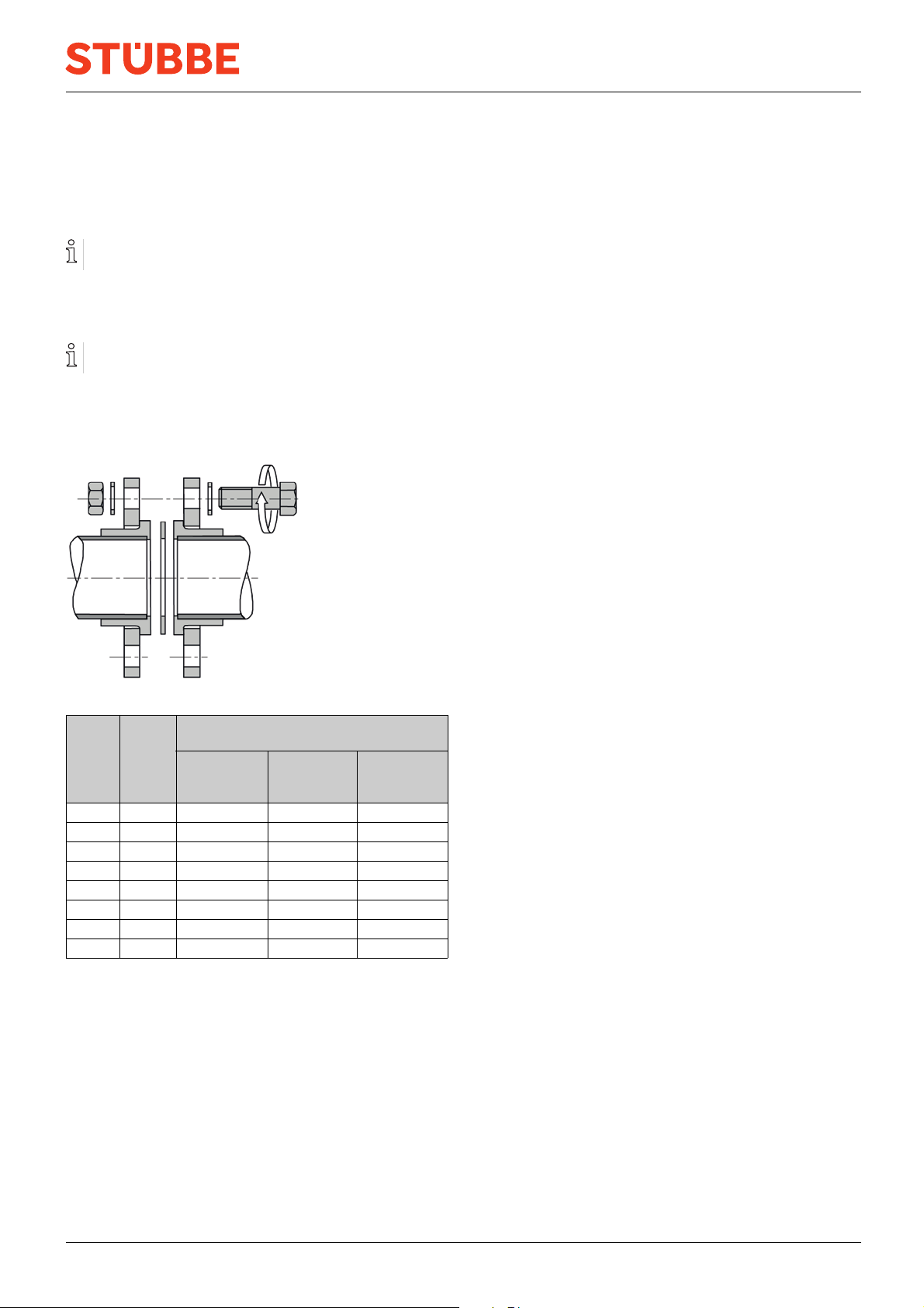
9.3 Flange installation ............................ 11
List of figures
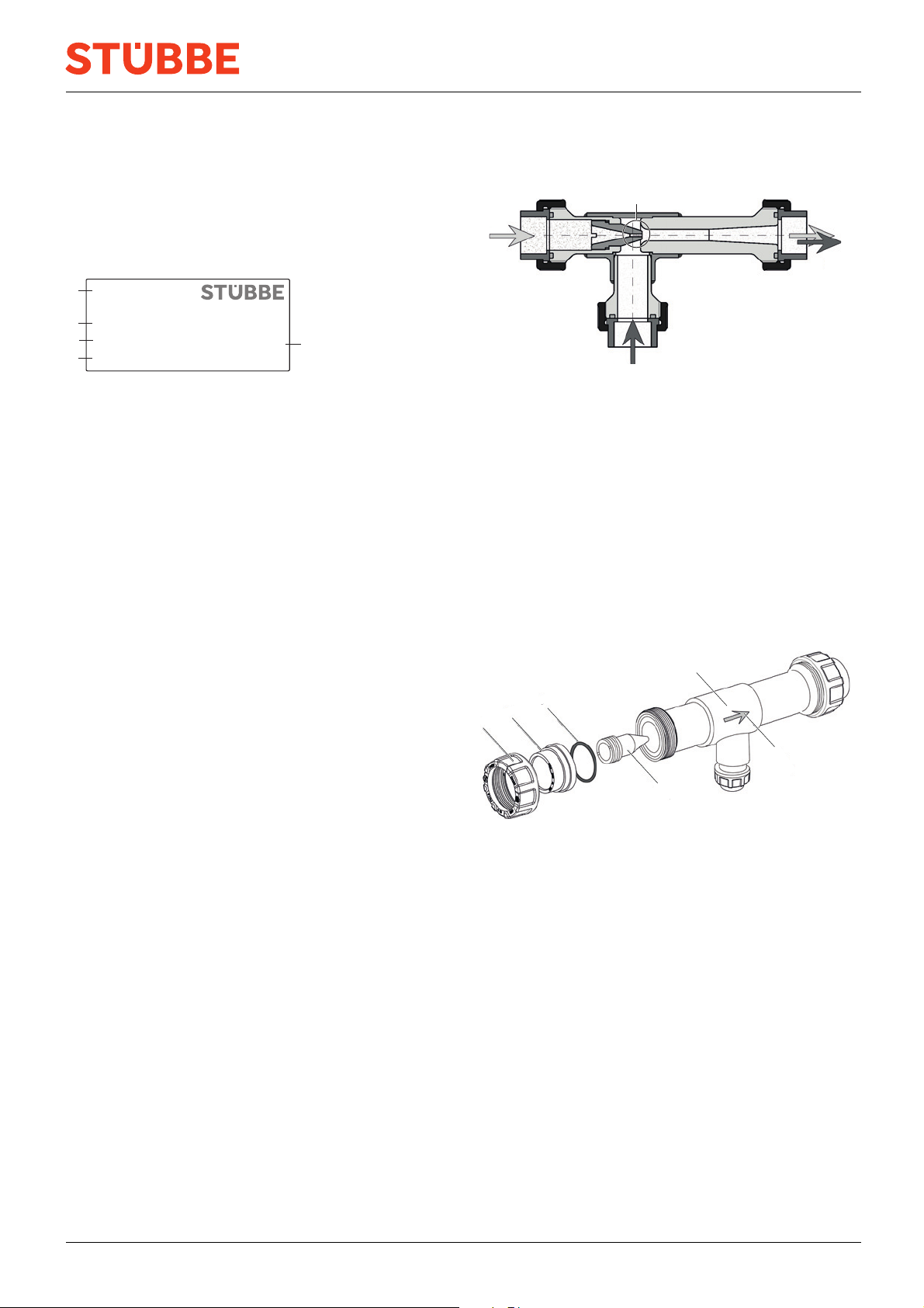
Fig. 1 Name plate (example) ....................... 5
Fig. 2 Function ....................................... 5
Fig. 3 Assembly ..................................... 5
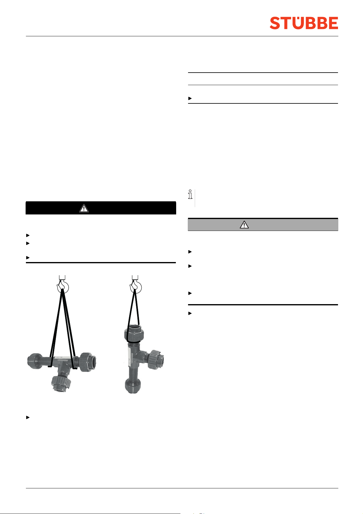
Fig. 4 Attach lifting gear (example) ................ 6
Fig. 5 Tightening torques ........................... 11
List of tables
Tab. 1 Other application documents, purpose and
where found .................................. 3
Tab. 2 Warnings and symbols ....................... 3
Tab. 3 Troubleshooting .............................. 10
Tab. 4 Tightening torques ........................... 11
2 SP 820 BA-2023.09.27 EN 302 535

About this document
1 About this document
This manual
• is part of the fitting
• applies to all series referred to
• it describes safe and proper operation during all operating
phases
1.1 Target groups
Operating company
• Responsibilities:
– Keep this manual available at the place of operation,
also for future use.
– Ensure that employees read and observe this manual
and other applicable documents, especially the safety
instructions and warnings.
– Observe any additional country-specific rules and reg-
ulations that relate to the system.
Qualified personnel, fitter
• Mechanics qualification:
– Qualified employees with additional training for fitting
the respective pipework
• Electrical qualification:
– Qualified electrician
• Responsibility:
– Read, observe and follow this manual and the other
applicable documents, especially all safety instructions
and warnings.
1.2 Other applicable documents
Resistance lists
Resistance of materialsusedtochemicals
www.stuebbe.com/pdf/300051.pdf
Data sheet
Technical specifications, conditions of
operation
www.stuebbe.com/pdf/302541.pdf
CE declaration of conformity
Conformity with standards
www.stuebbe.com/pdf/300168.pdf
Tab. 1 Other application documents, purpose
and where found
1.3 Warnings and symbols
Symbol Meaning
• Immediate acute risk
• Death, serious bodily harm
• Potentially acute risk
• Death, serious bodily harm
• Potentially hazardous situation
• Minor injury
• Potentially hazardous situation
• Material damage
Safety warning sign
Take note of all information
highlighted by the safety warning
sign and follow the instructions to
avoid injury or death.
Instruction
1., 2., ... Multiple-step instructions
Precondition
→Cross reference
Information, notes
Tab. 2 Warnings and symbols
302 535 BA-2023.09.27 EN SP 820 3

Safety instructions
2 Safety instructions
The manufacturer accepts no liability for damages caused
by disregarding any of the documentation.
2.1 Intended use
• The fitting is intended for the following applications:
– Mixing, dosing and conveying liquid and solids-free
media
– Evacuating air from pipes and immersion tanks
– Pumping out immersion tanks and pits
• Only use the fitting with suitable media (→Resistance
lists).
• Adhere to the operational limits (→Data sheet).
2.2 General safety instructions
Read and observe the following regulations before carrying
out any work.
2.2.1 Obligations of the operating company
Safety-conscious working
• Only operate the fitting if it is in perfect technical condition
and only use it as intended, remaining aware of safety and
risks, and adhering to the instructions in this manual.
• Ensure that the following safety aspects are observed and
monitored:
– Intended use
– Statutory or other safety and accident-prevention reg-
ulations
– Safety regulations governing the handling of haz-
ardous substances
– Applicable standards and guidelines in the country
where the pump is operated
– Applicable guidelines of the operator
• Make personal protective equipment available.
Qualified personnel
• Ensure all personnel tasked with work on the fitting have
read and understood this manual and all other applicable
documents, especially the safety, maintenance and repair
information, before they start any work.
• Organize responsibilities, areas of competence and the
supervision of personnel.
• The following work should be carried out by specialist tech-
nicians only:
– Installation, repair and maintenance work
– Work on the electrical system
• Make sure that personnel to be trained only
work on the fitting under the supervision of specialist tech-
nicians.
2.2.2 Obligations of personnel
• Observe the instructions on the fitting and keep them leg-
ible, e.g. name plate and identification marking for fluid
connections.
• Only carry out work on the fitting if the following require-
ments are met:
– System is empty
– System has been flushed
– System is depressurized
– System has cooled down
– System is secured against being switched back on
again
• Do not modify the fitting in any way.
2.3 Hazardous media
• When handling hazardous media (e.g. hot, flammable,
explosive, toxic, hazardous to health or the environment),
observe the safety regulations for the handling of haz-
ardous substances.
• Use personal protective equipment when carrying out any
work on the fitting.
• Collect leaking pumped liquid and residues in a safe man-
ner and dispose of them in accordance with environmental
regulations.
4 SP 820 BA-2023.09.27 EN 302 535

Layout and Function
3 Layout and Function
3.1 Marking
3.1.1 Name plate
PVC-U • FPM
1
2
3
4
SP 820
PN/DN 10 / 40
Id No 213119
1407-87345 5
Hollwieser Str. 5, DE-32602 Vlotho
Fig. 1 Name plate (example)
1Type
2 ID number
3 Nominal pressure [bar] / Nominal diameter [mm]
4 Materials (body, seals)
5 Date of manufacture - Series number
3.2 Description
3.2.1 Features
• The fitting is intended for the following applications:
– Mixing, dosing and conveying liquid and solids-free
media
– Evacuating air from pipes and immersion tanks
– Pumping out immersion tanks and pits
• The direction of flow and the installation position must
match the directional arrow on the fitting
• The flow rate is adjustable by means of the pressure of the
propellant and the bore in the nozzle
• Connection variants available
– The screw connections are to DIN 8063 and the inserts
are to DIN/ISO
– The flange is to DIN EN 1092 (DIN 2501)
3.2.2 Function
1
2
3
4
Fig. 2 Function
The propellant medium (1) flows in the main direction of flow
through the nozzle installed in the water-jet pump. The cross-
sectional constriction caused by the nozzle bore (4) results in
an acceleration of the propellant medium, thus creating a vac-
uum in the area of the suction port (2), which sucks in any
pumped media (liquid or gaseous) present. The media leave
the water-jet pump together at discharge nozzle (3).
The suction quantity depends on the pressure of the propellant
medium and the size of the nozzle bore.
3.3 Assembly
12
4
3
5
6
Fig. 3 Assembly
1 Union nut
2 Insert
3 O-ring*
4 Housing
5 Direction of flow
6 Nozzle*
* Replacement parts
302 535 BA-2023.09.27 EN SP 820 5

Transport, Storage and Disposal
4 Transport, Storage and
Disposal
4.1 Unpacking and inspection on delivery
1. Unpack the fitting when received and inspect it for trans-
portation damage.
2. Report any transportation damage to the manufacturer
immediately.
3. Ensure that the information on the name plate agrees with
the order/design data.
4. For immediate installation, damage packaging material
according to local regulations.
– For later installation, leave the fitting in the original
packaging.
4.2 Transportation
DANGER
Death or limbs crushed as a result transported items
falling over or tilting.
Do not stand under suspended loads.
Use lifting gear appropriate for the total weight to be trans-
ported. Weight specification (→data sheet).
Attach lifting gear in accordance with the following diagram.
Fig. 4 Attach lifting gear (example)
Lift the fitting with properly installed lifting gear and position
it at the place of installation.
4.3 Storage
NOTE
Material damage due to inappropriate storage!
Store the fitting properly.
1. Make sure the storage room meets the following condi-
tions:
–Dry
– Frost-free
– Vibration-free
– Not in direct sunlight
– Storage temperature +10 °C to +60 °C
2. As far as possible, store the valve in its original packaging.
4.4 Disposal
Plastic parts can be contaminated by poisonous or radioac-
tive media to such an extent that cleaning will not be suffi-
cient.
WARNING
Risk of poisoning and environmental damage from
medium!
Use personal protective equipment when carrying out any
work on the fitting.
Before disposing of the fitting:
– Collect escaping medium and dispose separately
according to local regulations.
– Neutralize residues of medium in the fitting.
Remove plastic parts and damage them in accordance with
local regulations.
Dispose of the fitting in accordance with local regulations.
6 SP 820 BA-2023.09.27 EN 302 535

Installation and connection
5 Installation and connection
5.1 Preparations for installation
1. Ensure the design of the fitting is consistent with the pur-
pose intended:
– Materials used (→Type plate).
–Medium(→Order and design data).
2. Ensure the required operating conditions are met:
– Resistance of body and seal material to the medium
(→resistance lists).
– Media temperature (→Data sheet).
– Operating pressure (→Data sheet).
3. Consult with the manufacturer regarding any other use of
the device.
5.2 Planning pipelines
When mixing or dosing, suitable throttle valves, flow meters
or diaphragm seals in the pipeline are recommended.
WARNING
Risk of poisoning and environmental damage from
medium!
Leaks due to impermissible pipework forces.
Ensure that the fitting is not subject to any pulling or thrust-
ing forces or bending moments.
1. Plan pipes safely:
– No tensile or compressive forces
– No bending moments
– Adjust for changes in length due to temperature
changes (compensators, expansion shanks)
– Direction of flow according to the direction of the arrow
on the fitting
– Calming section min. 5 x DN before and after the valve
2. Dimensions (→Data sheet).
5.3 Design the layout of the fitting
For reference when designing the layout of the valve for
the specific application, guide values/characteristic curves
are described in the data sheet (→Data sheet). The char-
acteristic curves represent the relationships for propellant
medium and suction medium water at a suction height of
100 cm.
With other media (density/viscosity) the ratio may change.
STÜBBE recommends adapting the nozzle bore to the
desired operating point.
If no nozzle bore diameter is specified when ordering, a 1
mm bore will be delivered.
1. Check the characteristic curves and determine the required
diameter for the nozzle bore (→data sheet).
2. Remove the nozzle (→7.2.2 Disassemble and reassem-
ble the nozzle, Page 9 ).
3. Drill a hole in the nozzle tip with the required diameter.
4. Fit the nozzle.
5.4 Install the fitting
WARNING
Risk of poisoning and environmental damage from
medium!
Leak due to faulty installation.
Installation work on the pipes should only be performed
by technicians who have been specially trained for the
pipework in question.
NOTE
Material damage due to contamination of the fitting!
Make sure no contamination reaches the fitting.
Flush the pipe with a neutral medium.
The fitting is installed according to the connection type of
the pipes.
5.4.1 Connection with flange
1. Prepare pipe ends according to connection type.
2. Radially position the fitting and flat seal between the flange
ends.
3. Screw fitting (flange screws, nuts and
washers).
– Observe tightening torques (→9.3 Flange installation,
Page 11).
302 535 BA-2023.09.27 EN SP 820 7

Operation
5.4.2 Connection with sockets, nozzles or
female threads
1. Prepare pipe ends according to connection type.
2. Loosen the union nuts on the inserts and push same over
the pipeline end.
3. Connect inserts with pipe ends.
4. Radially push the valve between the pipeline ends and
tighten by hand using the union nuts.
5.5 Performing the hydrostatic test
Pressure test using neutral medium, e.g. water.
1. Pressurize the fitting. ensuring:
– Test pressure < permissible system pressure
– Test pressure < 1.5 PN
– Test pressure < PN + 5 bar
2. Check the fitting for leaks.
6Operation
6.1 Commissioning
Fitting correctly installed and connected
WARNING
Risk of injury and poisoning due to medium spraying out!
Use personal protective equipment when carrying out any
work on the fitting.
1. Open the supply for the propellant medium and the pumped
medium.
2. Check the desired suction quantity of the pumped medium.
If necessary, rearrange layout of the fitting (→5.3 Design
the layout of the fitting, Page 7 ).
3. After the initial stresses due to pressure and operating tem-
perature, check if the fitting is sealed.
8 SP 820 BA-2023.09.27 EN 302 535

Maintenance
7 Maintenance
7.1 Servicing
WARNING
Risk of injury and poisoning due to hazardous media
liquids!
Use personal protective equipment when carrying out
any work on the fitting.
1. Visual and function check (every three months):
– Normal operating conditions unchanged
–Noleaks
– No unusual operating noises or vibrations
2. Ensure that the fitting is functioning properly.
3. Clean the fitting with a moist cloth if necessary.
7.2 Maintenance
WARNING
Risk of injury and poisoning due to hazardous or hot
media!
Use personal protective equipment when carrying out any
work on the fitting.
Safely collect the media and dispose of it in accordance
with environmental regulations.
7.2.1 Removing fitting
1. Ensure that:
– System is empty
– System has been flushed
– System is depressurized
– System has cooled down
– System is secured against being switched back on
again
2. Depending on the variant, loosen the union nuts or the
flange connection.
3. Remove fitting from the pipe.
4. Decontaminate fitting if required.
– Dead space in the fitting may still contain medium.
7.2.2 Disassemble and reassemble the nozzle
Refer to the drawing (→3.3 Assembly, Page 5 ).
Fitting disassembled
1. Using a suitable tool, unscrew the nozzle counterclockwise
from the housing.
2. Depending on the activity, proceed as follows:
Action Action
Check the status Check the nozzle for damage
and replace it if necessary
(→7.3 Replacement parts
and return, Page 9 ).
Clean the nozzle If the nozzle is dirty, clean
itsothatthenozzleboreis
clear.
Check the nozzle
bore and adjust it
Determine the lay-
outofthefitting
(→5.3 Design the layout of
the fitting, Page 7 ).
3. Screw the nozzle clockwise into the housing.
4. Check the O-ring and clean or replace it depending on its
condition.
5. Install fitting (→5.4 Install the fitting, Page 7 ).
7.3 Replacement parts and return
1. Have the following information ready to hand when order-
ing spare parts (→Type plate).
– Fitting type
– ID number
– Nominal pressure and diameter
– Body and seal material
2. Please complete and enclose the document of compliance
for returns
(→www.stuebbe.com/en/service/download).
3. Use only spare parts from STÜBBE.
302 535 BA-2023.09.27 EN SP 820 9

Troubleshooting
8 Troubleshooting
WARNING
Risk of injury and poisoning due to hazardous or hot
media!
Use personal protective equipment when carrying out any
work on the fitting.
Safely collect the media and dispose of it in accordance
with environmental regulations.
Consult with the manufacturer regarding faults which are not
identified in the following table, or which cannot be traced to
the indicated causes.
Error Possible cause Corrective action
Nozzle not drilled Remove the nozzle and drill it out according to the design layout
(→5.3 Design the layout of the fitting, Page 7 ).
Nozzle clogged Disassemble and clean the nozzle (→7.2.2 Disassemble and
reassemble the nozzle, Page 9 ).
Fitting not creating
suction
Fitting incorrectly
installed
Install the fitting in accordance with direction of flow indicated by the
arrow.
Intake quantity too low Nozzle bore too small Check the design of the nozzle bore according to the available
parameters (e.g. pressure and quantity of the propellant medium,
suction height, back pressure of the system). If necessary, select a
larger nozzle bore (→5.3 Design the layout of the fitting, Page 7 ).
Check the design of the nozzle bore according to the available
parameters (e.g. pressure and quantity of the propellant medium,
suction height, back pressure of the system). If necessary, select a
smaller nozzle bore (→5.3 Design the layout of the fitting, Page 7 ).
Suction quantity too great Nozzleboretoolarge
For better metering, install a suitable fitting (such as a diaphragm valve
or metering ball valve) in the suction line.
Tab. 3 Troubleshooting
10 SP 820 BA-2023.09.27 EN 302 535

Appendix
9 Appendix
9.1 Technical specifications
Technical data (→Data sheet).
9.2 Replacement parts
Replacement parts (→3.3 Assembly, Page 5 ).
9.3 Flange installation
MD
Fig. 5 Tightening torques
Tightening *1) MD [Nm]
for the variants
d
[mm]
ND
[mm]
Flat sealing
ring
max. 10 bar
Profile seal
max. 16 bar
O-ring
max. 16 bar
20 15 10 10 10
25 20 12 12 12
32 25 15 12 12
40 32 20 15 15
50 40 25 15 15
63 50 30 20 20
75 65 35 20 20
90 80 35 20 20
Tab. 4 Tightening torques
1) Use a torque wrench
302 535 BA-2023.09.27 EN SP 820 11
Table of contents
Other Stübbe Water Pump manuals