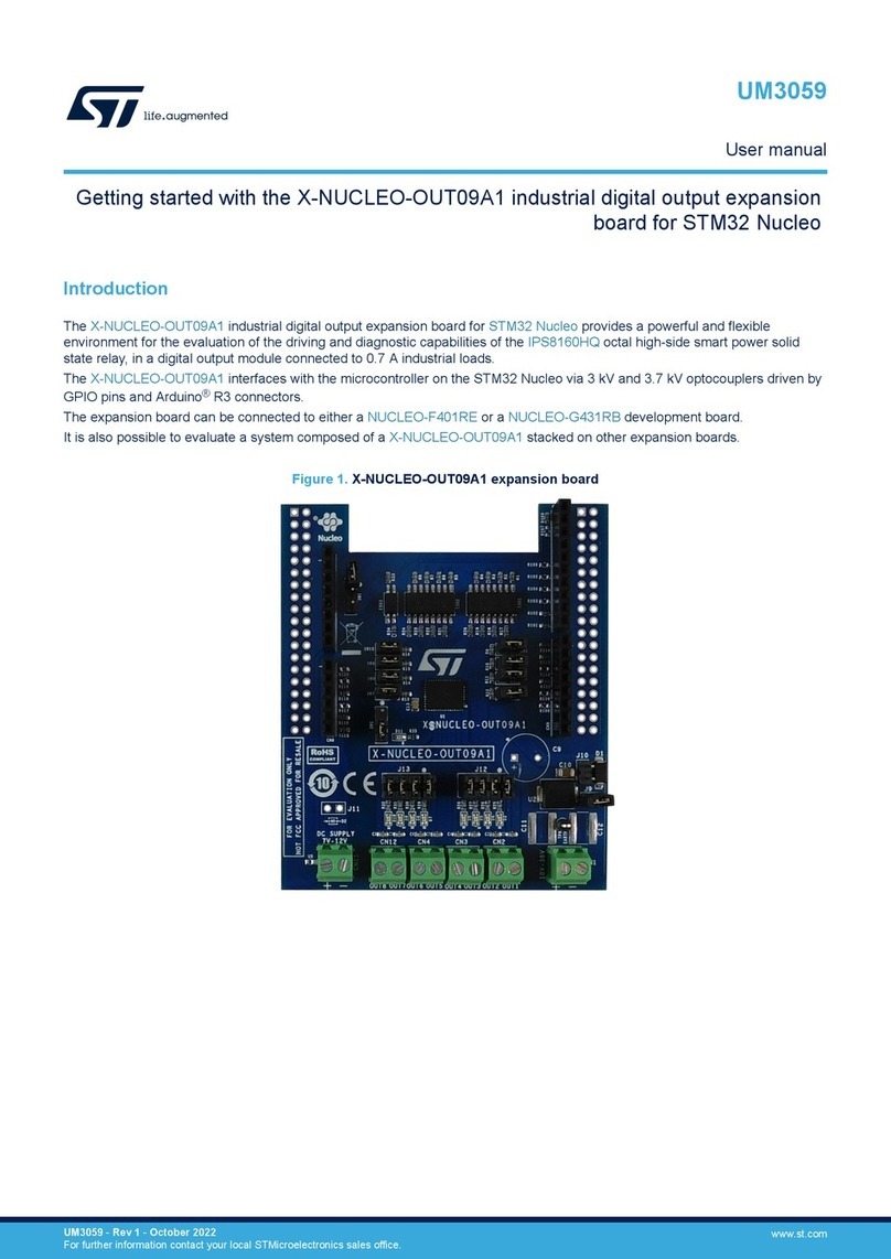
ST UM2168 User manual

October 2018 DocID030267 Rev 4 1/30
30
UM2168
User manual
Using STM32 motor control workbench with STSPIN32F0
and STSPIN32F0A
Introduction
The STSPIN32F0 and STSPIN32F0A are systems-in-package providing an integrated
solution suitable for driving 3-phase BLDC motors using different driving modes. The
integrated MCU (STM32F031x6) allows the performance of field-oriented control.
This document explains how to drive the STSPIN32F0 or STSPIN32F0A with FOC
algorithms, using the STM32 motor control workbench software to generate all the
parameter header files, to configure the STM32 PMSM FOC library according to application
needs.
To drive a motor with FOC algorithms using the STSPIN32F0 or STSPIN32F0A device,
follow this simple workflow:
1. Set up the hardware.
2. Use STM32 motor control workbench to configure the library and generate the code.
Figure 1. STM32 motor control workbench start window
3. Create the library and download the firmware.
4. Control the motor.
www.st.com

Contents UM2168
2/30 DocID030267 Rev 4
Contents
1 Set up hardware . . . . . . . . . . . . . . . . . . . . . . . . . . . . . . . . . . . . . . . . . . . . 3
2 Use STM32 motor control workbench to configure the library and
generate the code . . . . . . . . . . . . . . . . . . . . . . . . . . . . . . . . . . . . . . . . . . . 3
2.1 Create new project for ST STEVAL-SPIN3201 board . . . . . . . . . . . . . . . . 3
2.2 Create new project for ST STEVAL-SPIN3202 board . . . . . . . . . . . . . . . . 4
2.3 Create a new project for STSPIN32F0/A mounted on a custom board . . . 6
2.4 Customize parameters for application needs . . . . . . . . . . . . . . . . . . . . . . . 9
2.4.1 Motor parameters . . . . . . . . . . . . . . . . . . . . . . . . . . . . . . . . . . . . . . . . . . 9
2.4.2 Power stage parameters . . . . . . . . . . . . . . . . . . . . . . . . . . . . . . . . . . . . 10
2.4.3 Drive management parameters . . . . . . . . . . . . . . . . . . . . . . . . . . . . . . . 13
2.4.4 Control stage parameters . . . . . . . . . . . . . . . . . . . . . . . . . . . . . . . . . . . 17
3 Create the library and download the firmware . . . . . . . . . . . . . . . . . . . 23
3.1 Generation of the source code . . . . . . . . . . . . . . . . . . . . . . . . . . . . . . . . . 23
3.2 Using STSW-SPIN3201 . . . . . . . . . . . . . . . . . . . . . . . . . . . . . . . . . . . . . . 25
3.3 Compile and download the firmware . . . . . . . . . . . . . . . . . . . . . . . . . . . . 26
4 Control the motor . . . . . . . . . . . . . . . . . . . . . . . . . . . . . . . . . . . . . . . . . . 27
5 Revision history . . . . . . . . . . . . . . . . . . . . . . . . . . . . . . . . . . . . . . . . . . . 29

DocID030267 Rev 4 3/30
UM2168 Set up hardware
30
1 Set up hardware
Choose the board according to the target: you can use the ST STEVAL-SPIN3201 or
STEVAL-SPIN3202 boards or you can use a custom board;
Connect the board, power supply and plug in your motor.
2 Use STM32 motor control workbench to configure
the library and generate the code
The STM32 motor control workbench can be used to configure the FOC firmware library to
use in your application. The user can use the STEVAL-SPIN3201 or STEVAL-SPIN3202
boards or a custom board can be used.
2.1 Create new project for ST STEVAL-SPIN3201 board
The STEVAL-SPIN3201 board is a three-phase brushless DC motor driver board based on
the STSPIN32F0, a 3-phase controller with an integrated STM32 MCU.
The device provides an affordable and easy-to-use solution for the evaluation of the device
in low voltage motor driving applications such as fans, drones and power tools.
The board is designed for sensored or sensorless FOC algorithms with 3-shunt sensing. To
create a new project for the STM32 motor control workbench based on STEVAL-SPIN3201,
follow the procedure:
Open the STM32 motor control workbench v5.2;
Click on “New Project” and a parameter window appears;
Choose the “Inverter” board type and select the STEVAL-SPIN3201 from the dropdown
list (Figure 2). In this way, the application automatically loads all the hardware-related
parameters for the FOC library.
Figure 2. Parameter window for STEVAL-SPIN3201
From the motor list, one of the pre-configured motors or a generic starting model can
be selected (Figure 3);

Use STM32 motor control workbench to configure the library and generate the code UM2168
4/30 DocID030267 Rev 4
Figure 3. Pre-configured motor window
Click OK. A new project is now created according to the starting parameters selected.
A configuration window appears, allowing the parameters to be set for:
– “Motor”
– “Power Stage”
– “Drive Management” (i.e. FOC algorithm configuration)
– “Control Stage” (i.e. MCU configuration)
Using the STEVAL-SPIN3201 device, the configuration parameters for the Power Stage,
Drive Management, and Control Stage are already set.
2.2 Create new project for ST STEVAL-SPIN3202 board
The STEVAL-SPIN3202 board is a three-phase brushless DC motor driver board based on
the STSPIN32F0A, a 3-phase controller with integrated STM32 MCU.
The device provides an affordable and easy-to-use solution for the evaluation of the device
in low voltage motor driving applications such as fans, drones and power tools.
The board is designed for the sensored or sensorless FOC, with single shunt current
sensing.
To create a new project for the STM32 motor control workbench based on STEVAL-
SPIN3202 follow the procedure:
Open the STM32 motor control workbench v5.2;
Click on “New Project” and a parameter window appears;
Choose the “Inverter” board type and select the STEVAL-SPIN3202 from the dropdown
list (Figure 4). In this way, the application automatically loads all the hardware-related
parameters for the FOC library.
From the motor list, one of the pre-configured motors or a generic starting model can
be selected (Figure 5);
Click OK. A new project is now created according to the starting parameters selected.
A configuration window appears, allowing the parameters to be set for:
– “Motor”
– “Power Stage”
– “Drive Management” (i.e. FOC algorithm configuration)
– “Control Stage” (i.e. MCU configuration)

DocID030267 Rev 4 5/30
UM2168 Use STM32 motor control workbench to configure the library and generate the code
30
Using the STEVAL-SPIN3202 device, the configuration parameters for the Power Stage,
Drive Management and Control Stage are already set.
Figure 4. Parameter window for STEVAL-SPIN3202
Figure 5. Pre-configured motor window

Use STM32 motor control workbench to configure the library and generate the code UM2168
6/30 DocID030267 Rev 4
2.3 Create a new project for STSPIN32F0/A mounted on a
custom board
To create a new project for STM32 motor control workbench using a custom board, follow
the procedure:
Open the STM32 motor control workbench v5.2;
Click on New Project and a parameter window appears;
Select the options as shown in Figure 6:
Figure 6. Parameter window for custom board
From the motor list, one of the pre-configured motors or a generic starting model can
be selected (Figure 7);
Figure 7. Pre-configured motor window
Click OK. A new project is now created according to the starting parameters selected.

DocID030267 Rev 4 7/30
UM2168 Use STM32 motor control workbench to configure the library and generate the code
30
A configuration window appears, allowing the parameters to be set for:
– “Motor”
– “Power Stage”
– “Drive Management” (i.e. FOC algorithm configuration)
– “Control Stage” (i.e. MCU configuration)
Using a custom board, choose the configuration parameters for the Power Stage and
Control Stage that best fit your application;
To use the integrated MCU (STM32F031x6), remember that a limited number of pins
can be accessed, as can be seen in the STSPIN32F0 or in the STSPIN32F0A
datasheet. Here is a list of pins that can be used to access the integrated MCU for both
devices:
Table 1. STSPIN32F0: Accessible pins for integrated MCU
No. Name Function
4 PF0 MCU PF0
5 PF1 MCU PF1
7 NRST MCU reset pin
11 PA0 MCU PA0
12 PA1 MCU PA1
13 PA2 MCU PA2
14 PA3 MCU PA3
15 PA4 MCU PA4
16 PA5 MCU PA5
17 PA6 MCU PA6
18 3FG_PA7 3FG open-drain output or MCU PA7
19 PB1 MCU PB1
37 PA13_SWD_IO MCU PA13/SWDIO (system debug data via ASIC)
38 PA14_SWD_CLK MCU PA14/SWDCLK (system debug clock)
39 PB6 MCU PB6
40 PB7 MCU PB7

Use STM32 motor control workbench to configure the library and generate the code UM2168
8/30 DocID030267 Rev 4
Table 2. STSPIN32F0A: Accessible pins for integrated MCU
No. Name Function
4 PF0 MCU PF0
5 PF1 MCU PF1
7 NRST MCU reset pin
11 PA0 MCU PA0
12 PA1 MCU PA1
13 PA2 MCU PA2
14 PA3 MCU PA3
15 PA4 MCU PA4
16 PA5 MCU PA5
17 PA6 MCU PA6
18 PA7 MCU PA7
19 PB1 MCU PB1
37 PA13_SWD_IO MCU PA13/SWDIO (system debug data via ASIC)
38 PA14_SWD_CLK MCU PA14/SWDCLK (system debug clock)
39 PA15 MCU PA15
40 PB6 MCU PB6
41 PB7 MCU PB7
42 BOOT0 MCU BOOT0

DocID030267 Rev 4 9/30
UM2168 Use STM32 motor control workbench to configure the library and generate the code
30
2.4 Customize parameters for application needs
When a project is opened by the STM32 motor control workbench, a configuration window
appears allowing the user to easily manage parameters for the FOC firmware library. There
are 4 families of parameters that should be changed to best fit the characteristics of the
application.
Figure 8. STM32 motor control workbench configuration window
2.4.1 Motor parameters
In the configuration window the motor parameters can be manually inserted by clicking on
the motor symbol and filling the fields (Figure 9). If “save parameters” is clicked on, the user
can add their motor to the preset list of motors.

Use STM32 motor control workbench to configure the library and generate the code UM2168
10/30 DocID030267 Rev 4
Figure 9. Motor parameters window
2.4.2 Power stage parameters
There is a family of parameters which are not covered in Figure 10 that are related to the
hardware of the board.
Figure 10. Power stage setting

DocID030267 Rev 4 11/30
UM2168 Use STM32 motor control workbench to configure the library and generate the code
30
Using the STEVAL-SPIN3201 or STEVAL-SPIN3202 device, the Power Stage parameters
are already set. If the supply voltage is changed or if the hardware of the board is modified
(changing MOSFETs, adjusting the gain of the sensing circuitry, etc.) or if a custom board is
used, the user should set the parameters related to their application. In the configuration
window the Power Stage parameters can be manually inserted by choosing the area you
want to set.
Select the link for “Rated Bus Voltage” and set the voltage range related to your
application (Figure 11).
Figure 11. Rated bus voltage parameter
Select “Bus Voltage Sensing” and set the parameters for the sensing of the Vbus
(Figure 12).
Figure 12. Bus voltage sensing parameters

Use STM32 motor control workbench to configure the library and generate the code UM2168
12/30 DocID030267 Rev 4
In “Current Sensing” choose the sensing network. If the user wants to change the sensing
circuit, they should also change the model used by the algorithm by changing the “Current
reading topology” or the “Shunt resistor value” in the Current Sensing menu (Figure 13).
Figure 13. Current sensing menu
The user can calculate the Amplifying network gain through the STM32 motor control
workbench by setting the resistor in the Amplifying network Gain Calculator: in the current
sensing menu click on Calculate and then set your amplification network (Figure 14).

DocID030267 Rev 4 13/30
UM2168 Use STM32 motor control workbench to configure the library and generate the code
30
Figure 14. Amplifying network gain calculator
Click on “Power Switches” and set their characteristics.
Figure 15. Power switch parameters
2.4.3 Drive management parameters
There is a family of parameters, shown in Figure 16, that are related to the configuration of
the algorithm, for example, the start-up configuration of the algorithm, the control mode
chosen (Speed or Torque) and also gain parameters if needed.
In the configuration window the parameters related to the algorithm usage can be manually
inserted by clicking on the area you want to set.

Use STM32 motor control workbench to configure the library and generate the code UM2168
14/30 DocID030267 Rev 4
Figure 16. Drive management setting
In the Speed Sensing window choose “Sensor selection” to select the sensing
algorithm you want to use (Figure 17).
Figure 17. Sensor selection
To select the starting speed and the open loop current profile, right click on “Firmware
Drive Management” and choose “Start-up Parameters” in the dropdown menu.

DocID030267 Rev 4 15/30
UM2168 Use STM32 motor control workbench to configure the library and generate the code
30
Figure 18. Start-up parameters
This is an example of a basic control of speed and current in open loop. The red line is the
speed profile while the blue line is the current profile chosen by editing the parameters on
the left of the graph. At first, the algorithm aligns the motor, if the “Include alignment before
ramp-up” is enabled. After the alignment phase the current value is “Final current ramp
value”. Speed and current ramp is now applied and the “Minimum start-up output speed” is
the minimum speed accepted by the algorithm to close the loop. When the algorithm
converges, if the Rev-up FOC switchover is enabled, the passage to the closed loop is more
gradual.
Choosing Advanced customized profile the user can set a more elaborate profile for the
open loop ramp, as shown in Figure 19.

Use STM32 motor control workbench to configure the library and generate the code UM2168
16/30 DocID030267 Rev 4
Figure 19. : Advanced start-up parameters
Figure 20. Drive settings window
To select the PWM frequency, right click on “Firmware Drive Management” and choose
“Drive Settings”: note that the PWM frequency / Execution rate must be below 14 KHz,
so adjust the Execution rate if you want to increase PWM frequency. In the Drive Settings
window, the user can also select the control mode (Speed or Torque control) and the

DocID030267 Rev 4 17/30
UM2168 Use STM32 motor control workbench to configure the library and generate the code
30
Target speed for the application. The user can also set the Cut-off frequency for the
stability of closed loop (Figure 20).
2.4.4 Control stage parameters
There is a family of parameters, shown in Figure 21, that are related to the mapping of the
STM32 peripherals which should not be changed as long as the STEVAL-SPIN3201 or the
STEVAL-SPIN3202 board is used.
Figure 21. Control stage setting
Using the STEVAL-SPIN3201 or the STEVAL-SPIN3202 device, the general configuration
parameters for the Control Stage are already set. In the configuration window the Control
Stage parameters can be manually inserted by clicking on the area you want to set.
If custom HW is used remember to select the STSPIN32F0 or STSPIN32F0A as a
microcontroller in the “MCU and Clock Frequency” → MCU TYPE (Figure 22).

Use STM32 motor control workbench to configure the library and generate the code UM2168
18/30 DocID030267 Rev 4
Figure 22. MCU and clock frequency window
The “Digital I/O” →“Pin Map” (Figure 23), should follow the internal mapping of the
device, shown in Table 3. If you have selected the STSPIN32F0 or STSPIN32F0A as a
microcontroller, the “Digital I/O” → “Pin Map” is automatically configured and shouldn’t
be changed.
Table 3. Pin map for STSPIN32F0 and STSPIN32F0A
TIM1
CH1 A8
CH2 A9
CH3 A10
CH1N B13
CH2N B14
CH3N B15
BKIN B12

DocID030267 Rev 4 19/30
UM2168 Use STM32 motor control workbench to configure the library and generate the code
30
Figure 23. Digital I/O pin map for STSPIN32F0 and STSPIN32F0A
If the “Hall” sensor position feedback is used, set the correct Sensor selection in the
“Speed Sensing” window (Figure 17) and then in the Digital I/O →Hall sensor interface
(Figure 24); the Pin Map has to be set as shown in Table 4:
Table 4. Hall sensor interface for STSPIN32F0 and for STSPIN32F0A
TIM2
CH1 A0(1), A15(2)
CH2 A1
CH3 A2
1. If you use the ST STEVAL-SPIN3201 or STEVAL-SPIN3202 board, choose CH1 = A0.
2. A15 available only for STSPIN32F0A.

Use STM32 motor control workbench to configure the library and generate the code UM2168
20/30 DocID030267 Rev 4
Figure 24. Digital I/O Hall sensor settings for STEVAL-SPIN3201 and STEVAL-SPIN3202
If the “Encoder” position feedback is used, set the correct Sensor selection in the Speed
Sensing window (Figure 17) and in the Digital I/O → Encoder interface (Figure 25); the
Pin Map has to be set as shown in Table 5 for STSPIN32F0 or in Table 6 for
STSPIN32F0A.
Table 6. Encoder interface for STSPIN32F0A
Table 5. Encoder interface for STSPIN32F0
TIM2(1) TIM3
CH1 A0 or A5 CH1 A6
CH2 A1 CH2 A7
1. If you use the ST STEVAL-SPIN3201 board, choose TIM2 and CH1 = A0.
TIM2
CH1 A0(1), A5, A15
CH2 A1
1. If you use the STEVAL-SPIN3202 board, choose CH1 = A0.
This manual suits for next models
3
Table of contents
Other ST Computer Hardware manuals

ST
ST X-NUCLEO-GFX01M Series User manual

ST
ST X-CUBE-CELLULAR User manual

ST
ST X-NUCLEO-SNK1M1 User manual

ST
ST ST92163 User manual

ST
ST STDES-PFCBIDIR User manual

ST
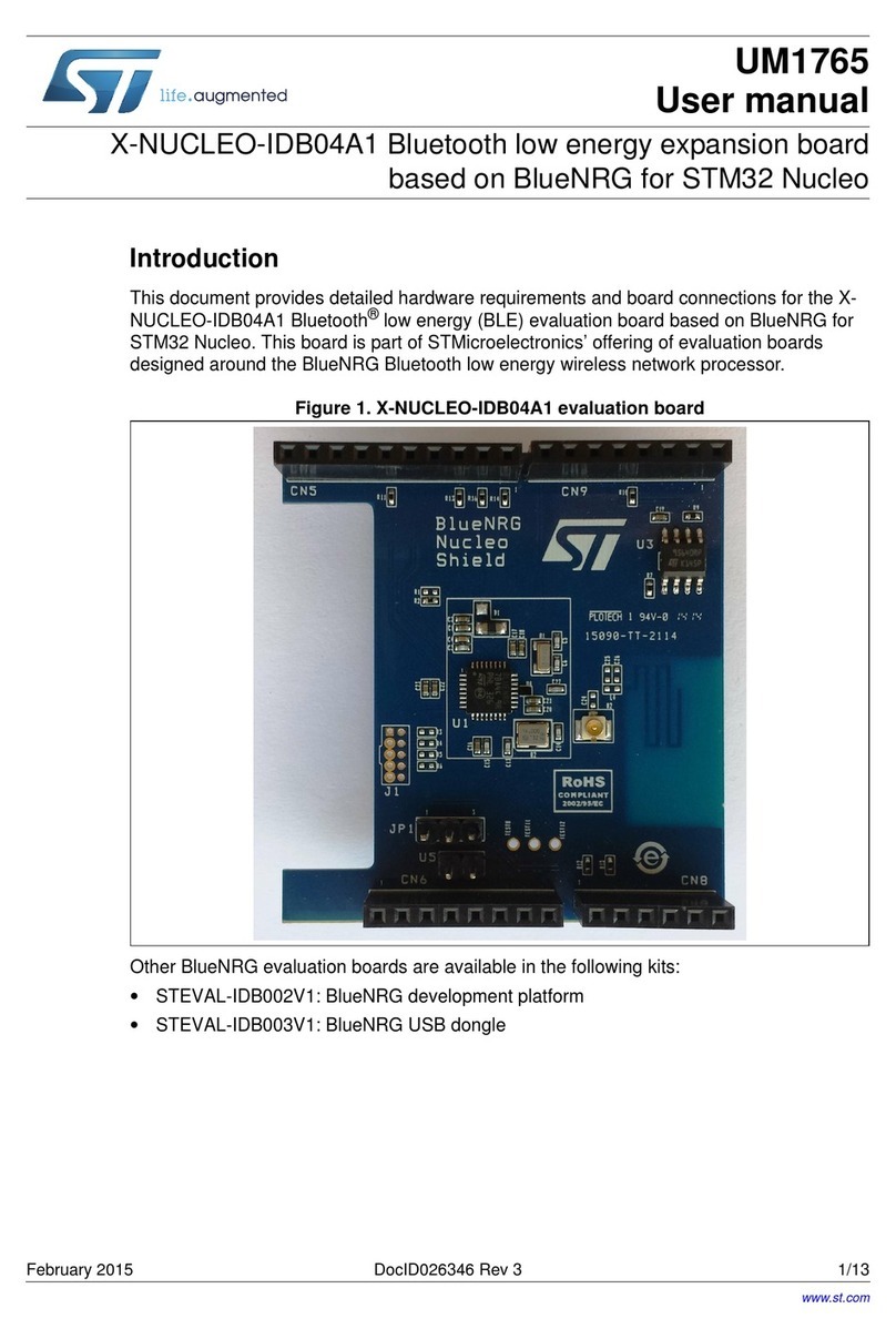
ST X-NUCLEO-IDB04A1 User manual
ST
ST X-NUCLEO-OUT10A1 User manual

ST
ST X-NUCLEO-BNRG2A1 User manual

ST
ST STM32W-RFCKIT User manual

ST
ST EVLKST8500GH-2 User manual