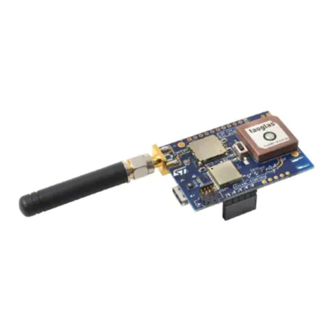
ST STM32429I-EVAL1 User manual

May 2021 UM1667 Rev 3 1/59
1
UM1667
User manual
STM32429I-EVAL evaluation board for STM32F429 MCUs
Introduction
The STM32429I-EVAL evaluation board is a complete demonstration and development
platform for STMicroelectronics Arm®Cortex®-M4 core-based STM32F429NIH6
microcontrollers. It features three I2C, six SPI with two muxed full-duplex I2S, SDIO, four
USART, four UART, two CAN, three 12-bit ADC, two 12-bit DAC, one SAI, 8- to 14-bit digital
camera module interface, internal 256+4 Kbyte SRAM and 2-Mbyte Flash memory, USB HS
OTG and USB FS OTG, Ethernet MAC, FMC interface, JTAG debugging support. This
evaluation board can be used as a reference design for user application development but it
is not considered as a final application.
The full range of hardware features on the board helps the user to evaluate all peripherals
(such as USB OTG HS, USB OTG FS, Ethernet, motor control, CAN, microSD™ card,
USART, Audio DAC and ADC, digital microphone, IrDA, CAN, RF-EEPROM, SRAM, NOR
Flash memory, SDRAM, 4.3" TFT LCD with a resistive touch panel, and others) and develop
his own applications. Extension headers make it possible to easily connect a daughterboard
for specific applications development.
The integrated ST-LINK/V2 provides an embedded in-circuit debugger and programmer for
the STM32 MCU.
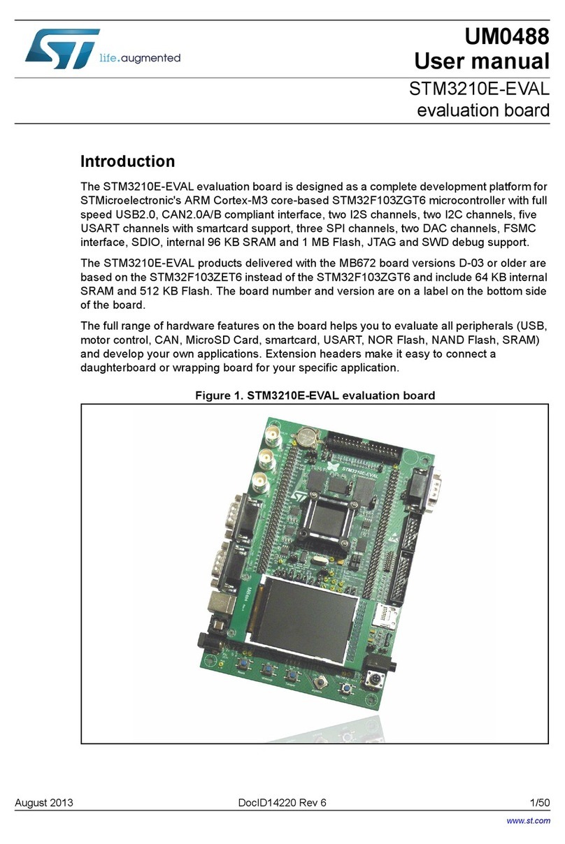
Figure 1. STM32429I-EVAL evaluation board
Picture is not contractual.
www.st.com
Downloaded from Arrow.com.

Contents UM1667
2/59 UM1667 Rev 3
Contents
1 Features . . . . . . . . . . . . . . . . . . . . . . . . . . . . . . . . . . . . . . . . . . . . . . . . . . . 7
2 Ordering information . . . . . . . . . . . . . . . . . . . . . . . . . . . . . . . . . . . . . . . . 8
2.1 Codification . . . . . . . . . . . . . . . . . . . . . . . . . . . . . . . . . . . . . . . . . . . . . . . . . 8
3 Development environment . . . . . . . . . . . . . . . . . . . . . . . . . . . . . . . . . . . . 9
3.1 System requirements . . . . . . . . . . . . . . . . . . . . . . . . . . . . . . . . . . . . . . . . . 9
3.2 Development toolchains . . . . . . . . . . . . . . . . . . . . . . . . . . . . . . . . . . . . . . . 9
3.3 Demonstration software . . . . . . . . . . . . . . . . . . . . . . . . . . . . . . . . . . . . . . . 9
3.4 Delivery recommendations . . . . . . . . . . . . . . . . . . . . . . . . . . . . . . . . . . . . . 9
4 Hardware layout and configuration . . . . . . . . . . . . . . . . . . . . . . . . . . . . 10
4.1 Development and debug support . . . . . . . . . . . . . . . . . . . . . . . . . . . . . . . 12
4.2 Power supply . . . . . . . . . . . . . . . . . . . . . . . . . . . . . . . . . . . . . . . . . . . . . . 13
4.3 Clock source . . . . . . . . . . . . . . . . . . . . . . . . . . . . . . . . . . . . . . . . . . . . . . . 15
4.4 Reset source . . . . . . . . . . . . . . . . . . . . . . . . . . . . . . . . . . . . . . . . . . . . . . 15
4.5 Boot option . . . . . . . . . . . . . . . . . . . . . . . . . . . . . . . . . . . . . . . . . . . . . . . . 16
4.6 Audio . . . . . . . . . . . . . . . . . . . . . . . . . . . . . . . . . . . . . . . . . . . . . . . . . . . . 16
4.7 USB OTG1 FS . . . . . . . . . . . . . . . . . . . . . . . . . . . . . . . . . . . . . . . . . . . . . 17
4.8 USB OTG2 HS and FS . . . . . . . . . . . . . . . . . . . . . . . . . . . . . . . . . . . . . . . 18
4.9 RS-232 and IrDA . . . . . . . . . . . . . . . . . . . . . . . . . . . . . . . . . . . . . . . . . . . 18
4.10 microSD™ card . . . . . . . . . . . . . . . . . . . . . . . . . . . . . . . . . . . . . . . . . . . . 19
4.11 RF-EEPROM . . . . . . . . . . . . . . . . . . . . . . . . . . . . . . . . . . . . . . . . . . . . . . 19
4.12 CAN . . . . . . . . . . . . . . . . . . . . . . . . . . . . . . . . . . . . . . . . . . . . . . . . . . . . . 19
4.13 Ethernet . . . . . . . . . . . . . . . . . . . . . . . . . . . . . . . . . . . . . . . . . . . . . . . . . . 20
4.14 Extension connector . . . . . . . . . . . . . . . . . . . . . . . . . . . . . . . . . . . . . . . . . 20
4.15 Memories . . . . . . . . . . . . . . . . . . . . . . . . . . . . . . . . . . . . . . . . . . . . . . . . . 21
4.16 Analog input . . . . . . . . . . . . . . . . . . . . . . . . . . . . . . . . . . . . . . . . . . . . . . . 21
4.17 Camera module . . . . . . . . . . . . . . . . . . . . . . . . . . . . . . . . . . . . . . . . . . . . 21
4.18 Display and input devices . . . . . . . . . . . . . . . . . . . . . . . . . . . . . . . . . . . . . 22
4.19 Motor control . . . . . . . . . . . . . . . . . . . . . . . . . . . . . . . . . . . . . . . . . . . . . . 23
Downloaded from Arrow.com.Downloaded from Arrow.com.

UM1667 Rev 3 3/59
UM1667 Contents
4
5 Connectors . . . . . . . . . . . . . . . . . . . . . . . . . . . . . . . . . . . . . . . . . . . . . . . 26
5.1 Motor control connector CN1 . . . . . . . . . . . . . . . . . . . . . . . . . . . . . . . . . . 26
5.2 Extension connector CN2 . . . . . . . . . . . . . . . . . . . . . . . . . . . . . . . . . . . . . 27
5.3 RF-EEPROM daughterboard connector CN3 . . . . . . . . . . . . . . . . . . . . . 28
5.4 Analog input connector CN4 . . . . . . . . . . . . . . . . . . . . . . . . . . . . . . . . . . 28
5.5 Camera module connector CN5 . . . . . . . . . . . . . . . . . . . . . . . . . . . . . . . . 29
5.6 Daughterboard extension connector CN6 and CN7 . . . . . . . . . . . . . . . . . 30
5.7 RS-232 connector CN8 . . . . . . . . . . . . . . . . . . . . . . . . . . . . . . . . . . . . . . 35
5.8 USB OTG2 HS Micro-AB connector CN9 . . . . . . . . . . . . . . . . . . . . . . . . 35
5.9 Ethernet RJ45 connector CN10 . . . . . . . . . . . . . . . . . . . . . . . . . . . . . . . . 36
5.10 Memory connectors CN11 and CN12 . . . . . . . . . . . . . . . . . . . . . . . . . . . . 36
5.11 ETM trace debugging connector CN13 . . . . . . . . . . . . . . . . . . . . . . . . . . 39
5.12 USB OTG1 FS Micro-AB connector CN14 . . . . . . . . . . . . . . . . . . . . . . . . 40
5.13 USB OTG2 FS Micro-AB connector CN15 . . . . . . . . . . . . . . . . . . . . . . . . 40
5.14 JTAG/SWD connector CN16 . . . . . . . . . . . . . . . . . . . . . . . . . . . . . . . . . . 41
5.15 microSD™ connector CN17 . . . . . . . . . . . . . . . . . . . . . . . . . . . . . . . . . . . 41
5.16 Power connector CN18 . . . . . . . . . . . . . . . . . . . . . . . . . . . . . . . . . . . . . . 42
5.17 ST-LINK/V2 programming connector CN19 . . . . . . . . . . . . . . . . . . . . . . . 42
5.18 TFT LCD connector CN20 . . . . . . . . . . . . . . . . . . . . . . . . . . . . . . . . . . . . 42
5.19 ST-LINK/V2 USB Type B connector CN21 . . . . . . . . . . . . . . . . . . . . . . . . 43
5.20 CAN D-type 9-pin male connector CN22 . . . . . . . . . . . . . . . . . . . . . . . . . 43
5.21 Audio jack CN23 . . . . . . . . . . . . . . . . . . . . . . . . . . . . . . . . . . . . . . . . . . . . 43
5.22 Audio terminal CN24 . . . . . . . . . . . . . . . . . . . . . . . . . . . . . . . . . . . . . . . . 44
5.23 ST-LINK/V2 programming Tag-connector CN25 . . . . . . . . . . . . . . . . . . . 44
6 STM32429I-EVAL evaluation board information . . . . . . . . . . . . . . . . . . 45
6.1 Product marking . . . . . . . . . . . . . . . . . . . . . . . . . . . . . . . . . . . . . . . . . . . . 45
6.2 STM32429I-EVAL product history . . . . . . . . . . . . . . . . . . . . . . . . . . . . . . 46
6.2.1 Product identification STM32429I-EVAL1/ . . . . . . . . . . . . . . . . . . . . . . . 46
6.2.2 Product identification VA32F429I$AX1 . . . . . . . . . . . . . . . . . . . . . . . . . 46
6.3 Board revision history . . . . . . . . . . . . . . . . . . . . . . . . . . . . . . . . . . . . . . . . 46
6.3.1 MB1045 . . . . . . . . . . . . . . . . . . . . . . . . . . . . . . . . . . . . . . . . . . . . . . . . . 46
6.3.2 MB1046 . . . . . . . . . . . . . . . . . . . . . . . . . . . . . . . . . . . . . . . . . . . . . . . . . 46
6.3.3 MB1066 . . . . . . . . . . . . . . . . . . . . . . . . . . . . . . . . . . . . . . . . . . . . . . . . . 46
Downloaded from Arrow.com.Downloaded from Arrow.com.Downloaded from Arrow.com.

Contents UM1667
4/59 UM1667 Rev 3
6.3.4 MB1020 . . . . . . . . . . . . . . . . . . . . . . . . . . . . . . . . . . . . . . . . . . . . . . . . . 46
6.4 Board known limitations . . . . . . . . . . . . . . . . . . . . . . . . . . . . . . . . . . . . . . 47
6.4.1 MB1045 . . . . . . . . . . . . . . . . . . . . . . . . . . . . . . . . . . . . . . . . . . . . . . . . . 47
6.4.2 MB1046 . . . . . . . . . . . . . . . . . . . . . . . . . . . . . . . . . . . . . . . . . . . . . . . . . 47
6.4.3 MB1066 . . . . . . . . . . . . . . . . . . . . . . . . . . . . . . . . . . . . . . . . . . . . . . . . . 47
6.4.4 MB1020 . . . . . . . . . . . . . . . . . . . . . . . . . . . . . . . . . . . . . . . . . . . . . . . . . 47
Appendix A STM32429I-EVAL I/O assignment . . . . . . . . . . . . . . . . . . . . . . . . . . . 48
Appendix B Mechanical dimensions. . . . . . . . . . . . . . . . . . . . . . . . . . . . . . . . . . . 55
Appendix C Federal Communications Commission (FCC)
and ISED Canada Compliance Statements . . . . . . . . . . . . . . . . . . . 56
C.1 FCC Compliance Statement . . . . . . . . . . . . . . . . . . . . . . . . . . . . . . . . . . . 56
C.2 ISED Compliance Statement. . . . . . . . . . . . . . . . . . . . . . . . . . . . . . . . . . . 56
Appendix D CE conformity . . . . . . . . . . . . . . . . . . . . . . . . . . . . . . . . . . . . . . . . . . 57
Revision history . . . . . . . . . . . . . . . . . . . . . . . . . . . . . . . . . . . . . . . . . . . . . . . . . . . . 58
Downloaded from Arrow.com.Downloaded from Arrow.com.Downloaded from Arrow.com.Downloaded from Arrow.com.
UM1667 Rev 3 5/59
UM1667 List of tables
5
List of tables
Table 1. Ordering information . . . . . . . . . . . . . . . . . . . . . . . . . . . . . . . . . . . . . . . . . . . . . . . . . . . . . . . 8
Table 2. Codification explanation . . . . . . . . . . . . . . . . . . . . . . . . . . . . . . . . . . . . . . . . . . . . . . . . . . . . 8
Table 3. Power related jumpers . . . . . . . . . . . . . . . . . . . . . . . . . . . . . . . . . . . . . . . . . . . . . . . . . . . . 13
Table 4. 32.786 kHz crystal X1 related solder bridges . . . . . . . . . . . . . . . . . . . . . . . . . . . . . . . . . . . 15
Table 5. 25 MHz crystal X2 related solder bridges . . . . . . . . . . . . . . . . . . . . . . . . . . . . . . . . . . . . . . 15
Table 6. Boot related switches . . . . . . . . . . . . . . . . . . . . . . . . . . . . . . . . . . . . . . . . . . . . . . . . . . . . . 16
Table 7. Audio related jumpers. . . . . . . . . . . . . . . . . . . . . . . . . . . . . . . . . . . . . . . . . . . . . . . . . . . . . 17
Table 8. USB OTG2 configuration . . . . . . . . . . . . . . . . . . . . . . . . . . . . . . . . . . . . . . . . . . . . . . . . . . 18
Table 9. RS-232 and IrDA related jumper . . . . . . . . . . . . . . . . . . . . . . . . . . . . . . . . . . . . . . . . . . . . 18
Table 10. CAN related jumpers . . . . . . . . . . . . . . . . . . . . . . . . . . . . . . . . . . . . . . . . . . . . . . . . . . . . . 19
Table 11. Ethernet related jumper . . . . . . . . . . . . . . . . . . . . . . . . . . . . . . . . . . . . . . . . . . . . . . . . . . . 20
Table 12. Ethernet related solder bridges. . . . . . . . . . . . . . . . . . . . . . . . . . . . . . . . . . . . . . . . . . . . . . 20
Table 13. NOR Flash memory related jumpers . . . . . . . . . . . . . . . . . . . . . . . . . . . . . . . . . . . . . . . . . 21
Table 14. LCD modules connector (CN20). . . . . . . . . . . . . . . . . . . . . . . . . . . . . . . . . . . . . . . . . . . . . 22
Table 15. Motor control related solder bridges . . . . . . . . . . . . . . . . . . . . . . . . . . . . . . . . . . . . . . . . . . 25
Table 16. Motor control connector CN1 . . . . . . . . . . . . . . . . . . . . . . . . . . . . . . . . . . . . . . . . . . . . . . . 26
Table 17. Extension connector CN2 . . . . . . . . . . . . . . . . . . . . . . . . . . . . . . . . . . . . . . . . . . . . . . . . . . 27
Table 18. RF-EEPROM daughterboard connector CN3. . . . . . . . . . . . . . . . . . . . . . . . . . . . . . . . . . . 28
Table 19. Analog input-output connector CN4 . . . . . . . . . . . . . . . . . . . . . . . . . . . . . . . . . . . . . . . . . . 28
Table 20. Camera module connector CN5 . . . . . . . . . . . . . . . . . . . . . . . . . . . . . . . . . . . . . . . . . . . . . 29
Table 21. Daughterboard extension connector CN6 . . . . . . . . . . . . . . . . . . . . . . . . . . . . . . . . . . . . . 30
Table 22. Daughterboard extension connector CN7 . . . . . . . . . . . . . . . . . . . . . . . . . . . . . . . . . . . . . 32
Table 23. RS-232 connector CN8 with ISP support . . . . . . . . . . . . . . . . . . . . . . . . . . . . . . . . . . . . . . 35
Table 24. USB OTG HS Micro-AB connector CN9. . . . . . . . . . . . . . . . . . . . . . . . . . . . . . . . . . . . . . . 35
Table 25. RJ45 connector CN10 . . . . . . . . . . . . . . . . . . . . . . . . . . . . . . . . . . . . . . . . . . . . . . . . . . . . 36
Table 26. Memory connector CN11 . . . . . . . . . . . . . . . . . . . . . . . . . . . . . . . . . . . . . . . . . . . . . . . . . . 36
Table 27. Memory connector CN12 . . . . . . . . . . . . . . . . . . . . . . . . . . . . . . . . . . . . . . . . . . . . . . . . . . 38
Table 28. ETM trace debugging connector CN13 . . . . . . . . . . . . . . . . . . . . . . . . . . . . . . . . . . . . . . . 39
Table 29. USB OTG1 FS Micro-AB connector CN14 . . . . . . . . . . . . . . . . . . . . . . . . . . . . . . . . . . . . . 40
Table 30. USB OTG2 FS Micro-AB connector CN15 . . . . . . . . . . . . . . . . . . . . . . . . . . . . . . . . . . . . . 40
Table 31. JTAG/SWD debugging connector CN15 . . . . . . . . . . . . . . . . . . . . . . . . . . . . . . . . . . . . . . 41
Table 32. microSD™ connector CN17 . . . . . . . . . . . . . . . . . . . . . . . . . . . . . . . . . . . . . . . . . . . . . . . . 42
Table 33. USB type B connector CN21 . . . . . . . . . . . . . . . . . . . . . . . . . . . . . . . . . . . . . . . . . . . . . . . 43
Table 34. CAN D-type 9-pin male connector CN22 . . . . . . . . . . . . . . . . . . . . . . . . . . . . . . . . . . . . . . 43
Table 35. Audio terminal CN24. . . . . . . . . . . . . . . . . . . . . . . . . . . . . . . . . . . . . . . . . . . . . . . . . . . . . . 44
Table 36. STM32429I-EVAL I/O assignment . . . . . . . . . . . . . . . . . . . . . . . . . . . . . . . . . . . . . . . . . . . 48
Table 37. Mechanical dimensions . . . . . . . . . . . . . . . . . . . . . . . . . . . . . . . . . . . . . . . . . . . . . . . . . . . 55
Table 38. Document revision history . . . . . . . . . . . . . . . . . . . . . . . . . . . . . . . . . . . . . . . . . . . . . . . . . 58
Downloaded from Arrow.com.Downloaded from Arrow.com.Downloaded from Arrow.com.Downloaded from Arrow.com.Downloaded from Arrow.com.
List of figures UM1667
6/59 UM1667 Rev 3
List of figures
Figure 1. STM32429I-EVAL evaluation board . . . . . . . . . . . . . . . . . . . . . . . . . . . . . . . . . . . . . . . . . . . 1
Figure 2. Hardware block diagram. . . . . . . . . . . . . . . . . . . . . . . . . . . . . . . . . . . . . . . . . . . . . . . . . . . 10
Figure 3. Evaluation board layout . . . . . . . . . . . . . . . . . . . . . . . . . . . . . . . . . . . . . . . . . . . . . . . . . . . 11
Figure 4. Orientation setting of 4.3 inch LCD daughterboard . . . . . . . . . . . . . . . . . . . . . . . . . . . . . . 23
Figure 5. PCB underside rework for motor control . . . . . . . . . . . . . . . . . . . . . . . . . . . . . . . . . . . . . . 24
Figure 6. PCB topside rework for motor control. . . . . . . . . . . . . . . . . . . . . . . . . . . . . . . . . . . . . . . . . 24
Figure 7. Motor control connector CN1 . . . . . . . . . . . . . . . . . . . . . . . . . . . . . . . . . . . . . . . . . . . . . . . 26
Figure 8. Extension connector CN2 top view. . . . . . . . . . . . . . . . . . . . . . . . . . . . . . . . . . . . . . . . . . . 27
Figure 9. RF-EEPROM daughterboard connector CN3 (front view) . . . . . . . . . . . . . . . . . . . . . . . . . 28
Figure 10. Analog input-output connector CN4 (top view) . . . . . . . . . . . . . . . . . . . . . . . . . . . . . . . . . . 28
Figure 11. Camera module connector CN5 (top view). . . . . . . . . . . . . . . . . . . . . . . . . . . . . . . . . . . . . 29
Figure 12. RS-232 connector (front view) . . . . . . . . . . . . . . . . . . . . . . . . . . . . . . . . . . . . . . . . . . . . . . 35
Figure 13. USB OTG2 HS Micro-AB connector CN9 (front view) . . . . . . . . . . . . . . . . . . . . . . . . . . . . 35
Figure 14. Ethernet RJ45 connector CN10 (front view) . . . . . . . . . . . . . . . . . . . . . . . . . . . . . . . . . . . . 36
Figure 15. ETM trace debugging connector CN13 (top view) . . . . . . . . . . . . . . . . . . . . . . . . . . . . . . . 39
Figure 16. USB OTG1 FS Micro-AB connector CN14 (front view). . . . . . . . . . . . . . . . . . . . . . . . . . . . 40
Figure 17. USB OTG2 FS Micro-AB connector CN15 (front view). . . . . . . . . . . . . . . . . . . . . . . . . . . . 40
Figure 18. JTAG/SWD debugging connector CN16 (top view) . . . . . . . . . . . . . . . . . . . . . . . . . . . . . . 41
Figure 19. microSD™ connector CN17 (front view). . . . . . . . . . . . . . . . . . . . . . . . . . . . . . . . . . . . . . . 41
Figure 20. Power supply connector CN18 . . . . . . . . . . . . . . . . . . . . . . . . . . . . . . . . . . . . . . . . . . . . . . 42
Figure 21. USB type B connector CN21 (front view) . . . . . . . . . . . . . . . . . . . . . . . . . . . . . . . . . . . . . . 43
Figure 22. CAN D-type 9-pin male connector CN22 (front view) . . . . . . . . . . . . . . . . . . . . . . . . . . . . . 43
Figure 23. Audio terminal CN24 (front view) . . . . . . . . . . . . . . . . . . . . . . . . . . . . . . . . . . . . . . . . . . . . 44
Figure 24. Mechanical dimensions . . . . . . . . . . . . . . . . . . . . . . . . . . . . . . . . . . . . . . . . . . . . . . . . . . . 55
Downloaded from Arrow.com.Downloaded from Arrow.com.Downloaded from Arrow.com.Downloaded from Arrow.com.Downloaded from Arrow.com.Downloaded from Arrow.com.
UM1667 Rev 3 7/59
UM1667 Features
58
1 Features
•STM32F429NIH6 microcontroller based on the Arm®Cortex®-M4 core(a)
•4.3-inch 480 × 272 pixel TFT LCD with resistive touch panel
•Camera module
•SAI Audio DAC
•Stereo MEMS microphone
•IEEE-802.3-2002 compliant Ethernet
•USB OTG HS and FS
•2-Gbyte (or more) SDIO interface microSD™ card
•RF-EEPROM on I2C compatible serial interface
•RS-232 communication
•CAN2.0A/B compliant connection
•IrDA transceiver
•8 M × 32-bit SDRAM, 1 M × 16-bit SRAM, 8 M × 16-bit NOR Flash memory
•Joystick with 4-direction control and selector
•Reset, WakeUp, Tamper or key button
•4 user color LEDs
•RTC with backup battery
•Potentiometer
•Board connectors:
– microSD™ card
– 3× USB Micro-AB and 1× USB Type-B
– Audio terminal connector for external speakers
– 3.5 mm stereo audio jack
– Motor control
–2×RS-232
– RJ45
– Extension connectors and memory connectors for daughterboard or wrapping
board
•Six 5 V power supply options: power jack, ST-LINK/V2, User USB HS, User USB FS1,
User USB FS2, daughterboard
•Debug with JTAG/SWD, ETM trace, and on-board ST-LINK/V2 debugger/programmer
•Comprehensive free software libraries and examples available with the STM32CubeF4
MCU Package
•Support of a wide choice of Integrated Development Environments (IDEs) including
IAR Embedded Workbench®, MDK-ARM, and STM32CubeIDE
a. Arm is a registered trademark of Arm Limited (or its subsidiaries) in the US and/or elsewhere.
Downloaded from Arrow.com.Downloaded from Arrow.com.Downloaded from Arrow.com.Downloaded from Arrow.com.Downloaded from Arrow.com.Downloaded from Arrow.com.Downloaded from Arrow.com.
Ordering information UM1667
8/59 UM1667 Rev 3
2 Ordering information
To order the STM32429I-EVAL evaluation board, refer to Table 1. Additional information is
available from the datasheet and reference manual of the target STM32.
2.1 Codification
The meaning of the codification of the evaluation board is explained in Table 2.
Table 1. Ordering information
Order code Board reference Target STM32
STM32429I-EVAL
MB1045
MB1046(1)
MB1066(2)
MB1020(3)
1. Mounted LCD screen.
2. Mounted camera daughteroard
3. Mounted ANT7-M24LR-A dual-interface EEPROM board.
STM32F429NIH6
Table 2. Codification explanation
STM32XYYZ-EVAL Description Example: STM32429I-EVAL
XMCU series in STM32 32-bit
Arm Cortex MCUs STM32F4 Series
YY MCU product line in the series STM32F429
ZSTM32 Flash memory size:
– I for 2 Mbytes 2 Mbytes
EVAL Board type Evaluation board
Downloaded from Arrow.com.Downloaded from Arrow.com.Downloaded from Arrow.com.Downloaded from Arrow.com.Downloaded from Arrow.com.Downloaded from Arrow.com.Downloaded from Arrow.com.Downloaded from Arrow.com.
UM1667 Rev 3 9/59
UM1667 Development environment
58
3 Development environment
3.1 System requirements
•Windows®OS (7, 8 and 10), Linux® (a) 64-bit, or macOS® (b) (c)
•USB Type-A or USB Type-C®to Type-B cable
3.2 Development toolchains
•IAR Systems®- IAR Embedded Workbench®(d)
•Keil®- MDK-ARM(d)
•STMicroelectronics - STM32CubeIDE
3.3 Demonstration software
Demonstration software is preloaded in the Flash memory of the board for easy
demonstration of the device peripherals in stand-alone mode. For more information and to
download the latest version, refer to the STM32429I-EVAL demonstration software on
www.st.com.
3.4 Delivery recommendations
Some verifications are needed before using the board for the first time to make sure that
nothing was damaged during shipment and that no components are unplugged or lost.
When the board is extracted from its plastic bag, please check that no component remains
in the bag.
The main components to verify are:
1. The 25 MHz crystal (X2) and 25 MHz crystal (X4), which may have been removed by a
shock from their sockets.
2. The microSD™ card, which may have been ejected from the connector CN17 (right
side of the board).
3. The dual-interface EEPROM board, which may have been unplugged from the
connector CN3 (top left corner of the board).
4. The camera module on the camera daughterboard (MB1066), which may have been
unplugged.
Warning: There is a risk of explosion if the battery is replaced by an
incorrect one. Make sure to dispose of used batteries
according to the instructions.
a. Linux®is a registered trademark of Linus Torvalds.
b. macOS®is a trademark of Apple Inc. registered in the U.S. and other countries.
c. All other trademarks are the property of their respective owners.
d. On Windows®only.
Downloaded from Arrow.com.Downloaded from Arrow.com.Downloaded from Arrow.com.Downloaded from Arrow.com.Downloaded from Arrow.com.Downloaded from Arrow.com.Downloaded from Arrow.com.Downloaded from Arrow.com.Downloaded from Arrow.com.
Hardware layout and configuration UM1667
10/59 UM1667 Rev 3
4 Hardware layout and configuration
The STM32429I-EVAL evaluation board is designed around the STM32F429NIH6 (216-pin
TFBGA package).
The hardware block diagram Figure 2 illustrates the connection between the
STM32F429NIH6 and peripherals (SDRAM, SRAM, NOR Flash memory, camera module,
color LCD, USB OTG connectors, motor control connector, USART, IrDA, Ethernet, audio,
CAN, RF-EEPROM, microSD™ card and embedded ST-LINK). Figure 3 helps the user to
locate these features on the actual evaluation board.
Figure 2. Hardware block diagram
MS32865V1
GPIO
OTG2 FS
I2C1
USART1
JTAG
Potentiometer
Joystick
LEDs
Key button
RF EEPROM
connector
RS-232
transceiver
IrDA
transceiver
RS-232
connector
Color TFT LCD
4.3’ WQVGA
SPI3
SAI1 Audio
Codec
Embedded
ST-LINK/V2
USB TypeB
connector
JTAG & trace
connector
Extension
connectors
for GPIOs
Digital microphone
STM32F429NIH6
CAN driver
& connector CAN
Motor control
connector
Comparator
SDRAM
SDIO
MicroSD
card
FMC
MII PHY Integrated RJ45
connector
OTG2 HS
ULPI
RGB
GPIO
IO
expandor
USB Micro-AB
connector
USB power
switch
SRAM
NOR Flash
USB Micro-AB
connector
OTG1 FS USB Micro-AB
connector
USB power
switch
Audio terminal
connector
Memory
connectors
DCMI
I2C1
Camera
Extension
connector
2.8 V regulator
1.8 V regulator
3.3 V regulator
= I/O shared with motor control
Downloaded from Arrow.com.Downloaded from Arrow.com.Downloaded from Arrow.com.Downloaded from Arrow.com.Downloaded from Arrow.com.Downloaded from Arrow.com.Downloaded from Arrow.com.Downloaded from Arrow.com.Downloaded from Arrow.com.Downloaded from Arrow.com.
UM1667 Rev 3 11/59
UM1667 Hardware layout and configuration
58
Figure 3. Evaluation board layout
CN3
RF EEPROM
daughter board
connector
CN5
camera
extension
connector
CN6, CN7
extension
headers
U3
STM32F429NIH6
CN8
USART1
CN11, CN12
memory
headers
CN9
USB
OTG2 HS
CN14
USB
OTG1 FS
CN15
USB
OTG2 FS
CN18
power jack
CN21
ST-LINK/V2
USB
LD11
ST-LINK/V2
COM LED
U19
digital
microphone
(Left)
4 color
LEDS
RV1
potentiometer B1
reset
button B2
wakeup
button
B4
joystick
B3
tamper/key
button
CN20
color LCD
connector
CN24
audio terminal
connector
U18
digital
microphone
(Right)
CN23
audio jack
CN22
CAN
CN17
MicroSD
card
CN16
JTAG/SWD
CN10
Ethernet
RJ45
connector
CN13
ETM TRACE
U1
IrDA
CN2
connector
CN1
motor control
connector
MS32868V1
extension
Downloaded from Arrow.com.Downloaded from Arrow.com.Downloaded from Arrow.com.Downloaded from Arrow.com.Downloaded from Arrow.com.Downloaded from Arrow.com.Downloaded from Arrow.com.Downloaded from Arrow.com.Downloaded from Arrow.com.Downloaded from Arrow.com.Downloaded from Arrow.com.
Hardware layout and configuration UM1667
12/59 UM1667 Rev 3
4.1 Development and debug support
Version 2 of the ST-LINK (ST-LINK/V2) is embedded on the board. This tool allows on-board
program loading and debugging of the STM32 using a JTAG or SWD interface. Third-party
debug tools are also supported by the JTAG/SWD connector, CN16, and ETM Trace
connector, CN13.
A specific driver must be installed by the user on his PC to communicate with the embedded
ST-LINK/V2. An install shield called ST-LINK_V2_USBdriver.exe is available on the web. To
download and install this driver, refer to the Software and development tools page for
STM32 on www.st.com.
The embedded ST-LINK/V2 is connected to the PC via a standard USB cable connected to
connector CN21. The bicolor LED LD11 (COM) indicates the status of the communication as
follows:
•Red LED slow blinking/Off: At power on before USB initialization
•Red LED fast blinking/Off: After the first correct communication between PC and ST-
Link/V2 (enumeration)
•Red LED On: When initialization between PC and ST-LINK/V2 is successfully finished
•Green LED On: After successful target communication initialization
•Red/Green LED blinking: During communication with target
•Red LED On: Communication finished and OK
•Orange LED On: Communication failure
Note: The board can be powered via CN21 (embedded ST-LINK/V2 USB connector) even if an
external tool is connected to CN13 (ETM trace connector) or CN16 (external JTAG and
SWD connector).
By default ETM only works at 50 MHz clock because ETM signals are shared with other
peripherals.
If best performance of ETM is required (90 MHz), then R29, R32, R34, R36, R40, R114 and
R120 must be removed to reduce the stub on ETM signals. In this case SAI and camera are
not functional and NOR Flash memory and SRAM's addresses are limited on A18.
Caution: When an external high-speed debug tool connected to CN13 or CN16 is used for program
loading or debugging, it is recommended to remove ESD protections D9 to D13 connected
on JTAG signals.
Downloaded from Arrow.com.Downloaded from Arrow.com.Downloaded from Arrow.com.Downloaded from Arrow.com.Downloaded from Arrow.com.Downloaded from Arrow.com.Downloaded from Arrow.com.Downloaded from Arrow.com.Downloaded from Arrow.com.Downloaded from Arrow.com.Downloaded from Arrow.com.Downloaded from Arrow.com.
UM1667 Rev 3 13/59
UM1667 Hardware layout and configuration
58
4.2 Power supply
The STM32429I-EVAL evaluation board is designed to be powered by a 5 V DC power
supply and is protected by PolyZen from a wrong power plug-in event. It is possible to
configure the evaluation board to use any of following six sources for the power supply:
•5 V DC power adapter connected to CN18, the power jack on the board (Power Supply
Unit on silk screen of JP12 (E5V)).
•5 V DC power with 500 mA limitation from CN21, the USB type B connector of ST-
LINK/V2 (USB 5 V power source on silkscreen of JP12 (STlk)).
•5 V DC power with 500 mA limitation from CN9, the USB OTG2 HS Micro-AB
connector (USB 5V power source on silkscreen of JP12 (HS)).
•5 V DC power with 500 mA limitation from CN14, the USB OTG1 FS Micro-AB
connector (USB 5V power source on silkscreen of JP12 (FS1)).
•5 V DC power with 500 mA limitation from CN15, the USB OTG2 FS Micro-AB
connector (USB 5 V power source on silkscreen of JP12 (FS2)).
•5 V DC power from CN6 and CN7, the extension connectors for daughterboard
(daughterboard power source on silkscreen of JP12 (D5V)).
The power supply is configured by setting the related jumpers JP2, JP8 and JP12 as
described in Table 3.
Table 3. Power related jumpers
Jumper Description
JP2 JP2 is used to measure MCU current consumption manually by multimeter.
Default setting: Fitted
JP8
Vbat is connected to +3.3V when JP8 is set as shown to the right:
(Default setting)
Vbat is connected to battery when JP8 is set as shown to the right:
JP12(continued
on next page)
JP12 is used to select one of the six possible power supply resources.
For power supply from USB connector of ST-LINK/V2 (CN21) to
STM32429I-EVAL only, JP12 is set as shown to the right:
(Default setting)
For power supply jack (CN18) to the STM32429I-EVAL only,
JP12 is set as shown to the right:
For power supply from the daughterboard connectors (CN6 and
CN7) to STM32429I-EVAL only, JP12 is set as shown to the
right:
1 2 3
1 2 3
HS
FS1
FS2
D5V
PSU
STlk
HS
FS1
FS2
D5V
PSU
STlk
HS
FS1
FS2
D5V
PSU
STlk
Downloaded from Arrow.com.Downloaded from Arrow.com.Downloaded from Arrow.com.Downloaded from Arrow.com.Downloaded from Arrow.com.Downloaded from Arrow.com.Downloaded from Arrow.com.Downloaded from Arrow.com.Downloaded from Arrow.com.Downloaded from Arrow.com.Downloaded from Arrow.com.Downloaded from Arrow.com.Downloaded from Arrow.com.
Hardware layout and configuration UM1667
14/59 UM1667 Rev 3
The LED LD10 is lit when the STM32429I-EVAL evaluation board is powered by the 5 V
correctly.
Note: In order to avoid the impact of USB PHY and Ethernet PHY and get precise results of
current consumption on JP2, the following configurations must be implemented:
•Configure Ethernet PHY in Power Down Mode by setting low level of IO_Expander
(EXP_IO1).
•Configure USB HS PHY in Low Power Mode (Register Address=04,bit 6 in USB PHY).
JP12 (continued)
For power supply from USB OTG2 FS (CN15) to STM32429I-
EVAL only, JP12 is set as shown to the right:
For power supply from USB OTG1 FS (CN14) to STM32429I-
EVAL only, JP12 is set as shown to the right:
For power supply from USB OTG2 HS (CN9) to STM32429I-
EVAL only, JP12 is set as shown to the right:
For power supply from power supply jack(CN18) to both
STM32429I-EVAL and daughterboard connected on CN6 and
CN7, JP12 is set as shown to the right (daughterboard must not
have its own power supply connected)
Table 3. Power related jumpers (continued)
Jumper Description
HS
FS1
FS2
D5V
PSU
STlk
HS
FS1
FS2
D5V
PSU
STlk
HS
FS1
FS2
D5V
PSU
STlk
HS
FS1
FS2
D5V
PSU
STlk
Downloaded from Arrow.com.Downloaded from Arrow.com.Downloaded from Arrow.com.Downloaded from Arrow.com.Downloaded from Arrow.com.Downloaded from Arrow.com.Downloaded from Arrow.com.Downloaded from Arrow.com.Downloaded from Arrow.com.Downloaded from Arrow.com.Downloaded from Arrow.com.Downloaded from Arrow.com.Downloaded from Arrow.com.Downloaded from Arrow.com.
UM1667 Rev 3 15/59
UM1667 Hardware layout and configuration
58
4.3 Clock source
Two clock sources are available on the STM32429I-EVAL evaluation board for the
STM32F429NIH6 and embedded RTC.
The camera module, Ethernet PHY and USB PHY on the STM32429I-EVAL evaluation
board have their own clock sources.
•X1, 32.768 kHz crystal for embedded RTC.
•X2, 25 MHz crystal with socket for STM32F429NIH6 microcontroller, it can be removed
from the socket when an internal RC clock is used.
•X3, 24 MHz oscillator for camera module.
•X4, 25 MHz crystal with socket for Ethernet PHY.
•X5, 24 MHz crystal for USB OTG2 HS PHY.
Jumper JP6 for Ethernet clock refer to Section 4.13.
4.4 Reset source
The reset signal of STM32429I-EVAL evaluation board is low active. Reset sources include:
•Reset button B1
•Debugging tools from JTAG/SWD connector CN16 and ETM trace connector CN13
•Daughterboard from CN6
•Embedded ST-LINK/V2
Table 4. 32.786 kHz crystal X1 related solder bridges
Solder bridge Description
SB3
PC14 is connected to 32.786 kHz crystal when SB3 is open. (Default setting)
PC14 is connected to extension connector CN7 when SB3 is closed. In such case
R19 must be removed to avoid disturbance due to the 32.786 kHz quartz.
SB4
PC15 is connected to 32.786 kHz crystal when SB4 is open. (Default setting)
PC15 is connected to extension connector CN7 when SB4 is closed. In such case
R18 must be removed to avoid disturbance due to the 32.786 kHz quartz.
Table 5. 25 MHz crystal X2 related solder bridges
Solder bridge Description
SB5
PH0 is connected to 25 MHz crystal when SB5 is open. (Default setting)
PH0 is connected to extension connector CN6 when SB5 is closed. In such case
R20 must be removed to avoid disturbance due to the 25 MHz quartz
SB6
PH1 is connected to 25 MHz crystal when SB6 is open (Default setting).
PH1 is connected to extension connector CN7 when SB6 is closed. In such case
C23 and X2 must be removed to avoid disturbance due to the 25 MHz quartz.
Downloaded from Arrow.com.Downloaded from Arrow.com.Downloaded from Arrow.com.Downloaded from Arrow.com.Downloaded from Arrow.com.Downloaded from Arrow.com.Downloaded from Arrow.com.Downloaded from Arrow.com.Downloaded from Arrow.com.Downloaded from Arrow.com.Downloaded from Arrow.com.Downloaded from Arrow.com.Downloaded from Arrow.com.Downloaded from Arrow.com.Downloaded from Arrow.com.
Hardware layout and configuration UM1667
16/59 UM1667 Rev 3
4.5 Boot option
The STM32429I-EVAL evaluation board can boot from:
•Embedded user Flash memory
•System memory with boot loader for ISP
•Embedded SRAM for debugging
The boot option is configured by setting switch SW1 (BOOT0) and SW2 (BOOT1).
Note: The RS-232 boot loader mechanism is not supported on the STM32429I-EVAL.
4.6 Audio
An audio codec with 4 DACs and 2 ADCs inside is connected to the SAI interface of the
STM32F429NIH6 to support the TDM feature on the SAI port. This feature implements
audio recording on digital and analog microphone, and audio playback of different audio
streams on headphone and line-out at the same time.
It communicates with the STM32F429NIH6 via the I2C1 bus which is shared with the LCD,
camera module, RF-EEPROM, I/O expander and CN2 connector.
The analog microphone on the headset is connected to the ADC of the audio codec.
External speakers can be connected to the audio codec via audio terminal connector CN24.
There are two digital microphones (MEMs microphone) on the STM32429I-EVAL evaluation
board. They can be connected to either audio codec or the I2S port of STM32F429NIH6 by
setting jumpers as shown in Table 7.
Table 6. Boot related switches
Switch Boot description Switch configuration
SW1
and
SW2
STM32429I-EVAL boots from User Flash memory when
SW1 is set as shown to the right. SW2 is not required in
this configuration.
(Default setting)
STM32429I-EVAL boots from Embedded SRAM when
SW1 and SW2 are set as shown to the right.
STM32429I-EVAL boots from System Memory when SW1
and SW2 are set as shown to the right.
0 < > 1
SW
0 < > 1
SW1
SW2
0 < > 1
SW
SW
Downloaded from Arrow.com.Downloaded from Arrow.com.Downloaded from Arrow.com.Downloaded from Arrow.com.Downloaded from Arrow.com.Downloaded from Arrow.com.Downloaded from Arrow.com.Downloaded from Arrow.com.Downloaded from Arrow.com.Downloaded from Arrow.com.Downloaded from Arrow.com.Downloaded from Arrow.com.Downloaded from Arrow.com.Downloaded from Arrow.com.Downloaded from Arrow.com.Downloaded from Arrow.com.
UM1667 Rev 3 17/59
UM1667 Hardware layout and configuration
58
Note: The I2C address of the audio codec is 0b0011010.
4.7 USB OTG1 FS
The STM32429I-EVAL evaluation board supports USB OTG1 full speed communication via
a USB Micro-AB connector (CN14) and USB power switch (U9) connected to VBUS. The
evaluation board can be powered by this USB connection at 5 V DC with a 500 mA current
limitation.
Green LED LD7 will be lit in one of these cases:
•Power switch (U9) is ON and the STM32429I-EVAL is acting as a USB host.
•VBUS is powered by another USB host and the STM32429I-EVAL is acting as a USB
device.
Red LED LD8 will be lit when over-current occurs.
JP16 must be removed when using USB OTG FS as mentioned in Table 10.
Table 7. Audio related jumpers
Jumper Description
JP14
Data signal on digital microphone is connected to audio codec when JP14 is
set as shown to the right
(Default setting)
Data signal on digital microphone is connected to I2S port of STM32F429NIH6
when JP14 is set as shown to the right (also need to set JP5 according to this
table)
JP15
Clock signal on digital microphone is connected to audio codec when JP15 is
set as shown to the right
(Default setting)
Clock signal on digital microphone is connected to Timer output (PC7) of
STM32F429NIH6 when JP15 is set as shown to the right (also need to set
JP4 according to this table)
JP4
PB4 is as TDO/SWO signal when JP4 is set as shown to the right
(Default setting)
PB4 is connected to Timer input(PC6) of STM32F429NIH6 as I2S clock signal
when JP4 is set as shown to the right (also need to set JP15 according to this
table)
JP5
PD6 is as FMC_NWAIT signal when JP5 is set as shown to the right
(Default setting)
PD6 is connected to digital microphone as I2S data signal when JP5 is set as
shown to the right (also need to set JP14 according to this table):
JP13
Digital microphone power source is connected to +3.3V power when JP13 is
set as shown to the right
(Default setting)
Digital microphone power source is connected to MICBIAS1 from the audio
codec when JP13 is set as shown to the right. MICBIAS1 setting is requested
by digital microphone connected to codec.
1 2 3
1 2 3
1 2 3
1 2 3
1 2 3
1 2 3
1 2 3
1 2
3
1 2 3
1 2 3
Downloaded from Arrow.com.Downloaded from Arrow.com.Downloaded from Arrow.com.Downloaded from Arrow.com.Downloaded from Arrow.com.Downloaded from Arrow.com.Downloaded from Arrow.com.Downloaded from Arrow.com.Downloaded from Arrow.com.Downloaded from Arrow.com.Downloaded from Arrow.com.Downloaded from Arrow.com.Downloaded from Arrow.com.Downloaded from Arrow.com.Downloaded from Arrow.com.Downloaded from Arrow.com.Downloaded from Arrow.com.
Hardware layout and configuration UM1667
18/59 UM1667 Rev 3
4.8 USB OTG2 HS and FS
The STM32429I-EVAL evaluation board supports USB OTG2:
•High-speed communication via USB Micro-AB connector (CN9), USB high-speed PHY
(U7) for high-speed function
•Full-speed communication via USB Micro-AB connector (CN15)
The evaluation board can be powered by these USB connectors (CN9 or CN15) at 5 V DC
with a 500 mA current limitation.
Some OTG2 FS signals are shared with the OTG2 HS ULPI bus, so some PCB rework is
needed when using OTG2 FS (CN15) as shown in Table 8.
A USB power switch (U6) is connected on VBUS and provides power to either:
•CN9 (with R81 and R97 mounted and R83 and R95 un-mounted)
•CN15 (with R83 and R95 mounted and R81 and R97 un-mounted)
Green LED LD5 (for CN9) or LD9 (for CN15) will be lit when either:
•Power switch (U6) is ON and STM32429I-EVAL is acting as a USB host.
•VBUS is powered by another USB host, and STM32429I-EVAL is acting as a USB
device.
Red LED LD6 is lit if over-current occurs.
4.9 RS-232 and IrDA
RS-232 and IrDA communication is supported by 9-pin RS-232 D-type connector, CN8, and
IrDA transceiver, U1, which is connected to USART1 of the STM32F429NIH6 on the
STM32429I-EVAL evaluation board.
Table 8. USB OTG2 configuration
Function Mount Remove
OTG2 HS-CN9 (Default) R108, R112, R81,R97 R260, R264, R83,R95
OTG2 FS-CN15 R260, R264, R83,R95 R108, R112, R81,R97
Table 9. RS-232 and IrDA related jumper
Jumper Description
JP7
USART1_RX is connected to RS-232 transceiver and RS-232 communication
is enabled when JP7 is set as shown to the right
(Default setting):
USART1_RX is connected to IrDA transceiver and IrDA communication is
enabled when JP7 is set as shown to the right:
1 2 3
1 2 3
Downloaded from Arrow.com.Downloaded from Arrow.com.Downloaded from Arrow.com.Downloaded from Arrow.com.Downloaded from Arrow.com.Downloaded from Arrow.com.Downloaded from Arrow.com.Downloaded from Arrow.com.Downloaded from Arrow.com.Downloaded from Arrow.com.Downloaded from Arrow.com.Downloaded from Arrow.com.Downloaded from Arrow.com.Downloaded from Arrow.com.Downloaded from Arrow.com.Downloaded from Arrow.com.Downloaded from Arrow.com.Downloaded from Arrow.com.
UM1667 Rev 3 19/59
UM1667 Hardware layout and configuration
58
4.10 microSD™ card
A 2 GB (or more) microSD™ card can be connected to the STM32F429NIH6 SDIO port.
microSD™ card detection is managed by I/O expander GPIO15.
4.11 RF-EEPROM
An RF-EEPROM daughterboard is mounted on CN3 of the STM32429I-EVAL board via the
I2C1 bus. The RF-EEPROM can be accessed by the microcontroller via the I2C1 bus or by
radio frequency (RF) using a 13.56 MHz reader (for example, CR95HF).
The I2C address of RF-EEPROM is 0b1010000.
4.12 CAN
The STM32429I-EVAL evaluation board supports one channel of CAN2.0A/B complaint
CAN bus communication based on 3.3 V CAN transceiver.
High-speed mode, standby mode and slope control mode are available and are selected by
setting JP10.
Table 10. CAN related jumpers
Jumper Description
JP10
CAN transceiver is working in standby mode when JP10 is set as shown to
the right:
CAN transceiver is working in high-speed mode when JP10 is set as shown to
the right: (default setting)
CAN transceiver is working in slope control mode when JP10 is open.
JP11 CAN terminal resistor is enabled when JP11 is fitted.
Default setting: Not fitted
JP16
PA11 is only connected with USB FS1 DM signal when JP16 is not fitted. (default setting)
PA11 is connected with CAN RX signal when JP16 is fitted.
If the CAN function is being used, USB connector CN14 should be disconnected to leave
USB FS1_DM signal floating.
1 2 3
1 2 3
Downloaded from Arrow.com.Downloaded from Arrow.com.Downloaded from Arrow.com.Downloaded from Arrow.com.Downloaded from Arrow.com.Downloaded from Arrow.com.Downloaded from Arrow.com.Downloaded from Arrow.com.Downloaded from Arrow.com.Downloaded from Arrow.com.Downloaded from Arrow.com.Downloaded from Arrow.com.Downloaded from Arrow.com.Downloaded from Arrow.com.Downloaded from Arrow.com.Downloaded from Arrow.com.Downloaded from Arrow.com.Downloaded from Arrow.com.Downloaded from Arrow.com.

Hardware layout and configuration UM1667
20/59 UM1667 Rev 3
4.13 Ethernet
The STM32429I-EVAL evaluation board supports 10M/100M Ethernet communication by a
transceiver (U5) and integrated RJ45 connector (CN10). Ethernet PHY is connected to the
STM32F429NIH6 via the MII interface.
A 25 MHz clock can be generated by PHY or provided by MCO from the STM32F429NIH6
by setting jumper JP6 as shown in Table 11.
Note: Ethernet works properly in the default setting (which RX_ER is not connected to PI10 of
STM32F429NIH6) because PI10 is shared with data signal of SDRAM. If RX_ER signal is
needed, remove R244 and solder R43.
4.14 Extension connector
An extension connector (CN2) is intended for external board connection to the STM32429I-
EVAL evaluation board using cable FFSD-05-D-04.00-01-N.
The external board can exchange data with the STM32F429NIH6 via the I2C1 or SPI3
ports.
Table 11. Ethernet related jumper
Jumper Description
JP6
25 MHz clock is provided by external Crystal X4 when JP5 is set as shown to
the right: (Default setting)
25 MHz clock for MII is provided by MCO at PA8 when JP5 is set as shown to
the right:
Table 12. Ethernet related solder bridges
Solder bridges Description
SB7 MII CRS on U5 is connected to PA0 when SB7 is closed. PA0 is shared with
Wakeup button and MC_ENA. Default setting: Open
SB8 MII COL on U5 is connected to PH3 when SB8 is closed. PH3 is shared with
SDRAM chip select SDNE0. Default setting: Open
1 2 3
1 2 3
Downloaded from Arrow.com.Downloaded from Arrow.com.Downloaded from Arrow.com.Downloaded from Arrow.com.Downloaded from Arrow.com.Downloaded from Arrow.com.Downloaded from Arrow.com.Downloaded from Arrow.com.Downloaded from Arrow.com.Downloaded from Arrow.com.Downloaded from Arrow.com.Downloaded from Arrow.com.Downloaded from Arrow.com.Downloaded from Arrow.com.Downloaded from Arrow.com.Downloaded from Arrow.com.Downloaded from Arrow.com.Downloaded from Arrow.com.Downloaded from Arrow.com.Downloaded from Arrow.com.

Table of contents
Other ST Motherboard manuals

ST
ST SPC58NHADPT176S User manual

ST
ST STM32G081B-EVAL User manual

ST
ST UM1935 User manual

ST
ST STM32F779I-EVAL User manual

ST
ST STM32CubeF4 User manual

ST
ST STCC50x1 User manual

ST
ST STM32L1 Series Installation and operating instructions

ST
ST EVAL-L9177A User manual

ST
ST STEVAL-L6982CDR User manual

ST
ST STM32H753I-EVAL User manual