ST STEVAL-USBPD45H User manual

December 2017
DocID031190 Rev 1
1/33
www.st.com
UM2309
User manual
Getting started with the 45 W wall adapter solution for USB
Type-C Power Delivery
Introduction
This board has been physically tested and validated; it is not for sale.
This USB Power Delivery wall adapter is a USB-IF certified solution with a 45 W isolated power supply
with USB Power Delivery controller.
This USB Type-C PD wall power adapter design is for universal line voltage applications based on the
STCH02 Primary controller and STUSB4700 USB PD controller.
The 5 V, 9 V and 15 V USB output voltage profiles all have a 3 A rating.
The offline power supply is implemented in an isolated flyback topology based on the STCH02 quasi-
resonant controller with ultra-low standby power consumption. The USB Power Delivery (PD) is
managed by the STUSB4700 and is Type-C compatible: power negotiation, Vbus discharge,
protections, etc. are entirely managed by the IC.
The USB power supply architecture connects a power board with a controller board. This design
optimizes the form factor and lets you scale the power section up or down to suit different USB Power
Adapter applications.
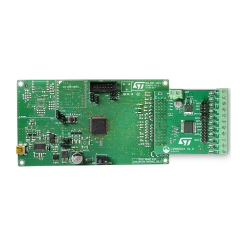
Figure 1: STEVAL-USBPD45H evaluation board

Contents
UM2309
2/33
DocID031190 Rev 1
Contents
1STEVAL-USBPD45H board description.........................................5
1.1 Main characteristics ..........................................................................5
2Schematics and list of components...............................................6
3Description of main components.................................................11
3.1 STUSB4700 stand-alone USB PD controller with integrated
discharge path (control board component U1).............................................11
3.2 STCH02 offline PWM quasi resonant controller for ultra-low standby
power supplies (power board component U3)..............................................11
3.3 Flyback transformer (power board component T1) .........................11
3.4 Other components...........................................................................12
4Layout of the PCB .........................................................................14
5Electrical safety.............................................................................16
6Getting started with the STEVAL-USBPD45H..............................17
6.1 Host system: P-NUCLEO-USB002 USB Type-C expansion pack...17
6.2 System setup ..................................................................................18
6.3 Connect STEVAL-USBPD45H and load test ..................................19
6.4 Profile change request....................................................................20
6.5 Configuration of STUSB4700 standalone USB PD controller .........21
7Test measurement reports............................................................23
7.1 STEVAL-USBPD45H efficiency measurements..............................23
7.2 STEVAL-USBPD45H voltage profile transition measurements.......25
7.2.1 Positive output voltage transitions (5 V to 15 V) .............................. 25
7.2.2 Negative output voltage transitions (15 V to 5 V)............................. 27
7.3 STEVAL-USBPD45H conducted EMI measurements.....................28
7.4 STEVAL-USBPD45H thermal measurements.................................30
8Revision history ............................................................................32

UM2309
List of tables
DocID031190 Rev 1
3/33
List of tables
Table 1: Power board bill of materials ........................................................................................................7
Table 2: Control board bill of materials.......................................................................................................9
Table 3: Electrical specifications (at 25°C unless otherwise specified)....................................................12
Table 4: Primary-Secondary Isolation elements - key parameters...........................................................16
Table 5: Efficiency measurement for 5 V at 120 VAC line voltage.............................................................23
Table 6: Efficiency measurement for 15 V at 120 VAC line voltage...........................................................24
Table 7: Efficiency measurement for 5 V at 230 VAC line voltage.............................................................24
Table 8: Efficiency measurement for 5 V at 230 VAC line voltage.............................................................25
Table 9: Positive voltage transition results ...............................................................................................26
Table 10: Negative voltage transition results............................................................................................28
Table 11: Document revision history ........................................................................................................32

List of figures
UM2309
4/33
DocID031190 Rev 1
List of figures
Figure 1: STEVAL-USBPD45H evaluation board.......................................................................................1
Figure 2: Power board schematic diagram.................................................................................................6
Figure 3: Control board schematic diagram ...............................................................................................9
Figure 4: Flyback transformer...................................................................................................................12
Figure 5: Power board PCB layout (top)...................................................................................................14
Figure 6: Power board PCB layout (bottom).............................................................................................14
Figure 7: Control board PCB layout (top) .................................................................................................14
Figure 8: Control board PCB layout (bottom) ...........................................................................................15
Figure 9: P-NUCLEO-USB002 STM32 Nucleo Pack for USB Type-C expansion ...................................17
Figure 10: P-NUCLEO-USB002 Nucleo Pack with USB1602 Expansion Board .....................................18
Figure 11: Setting up the complete testing environment..........................................................................19
Figure 12: STUSB graphical user interface tool .......................................................................................21
Figure 13: Efficiency measurement at 120 VAC line voltage.....................................................................23
Figure 14: Efficiency measurement at 230 VAC line voltage.....................................................................24
Figure 15: Output voltage transition 5 V to 15 V - no load .......................................................................25
Figure 16: Output voltage transition 5 V to 15 V - full load.......................................................................26
Figure 17: Positive voltage transition........................................................................................................26
Figure 18: Output voltage transition 15 V to 5 V - no load .......................................................................27
Figure 19: Output voltage transition 15 V to 5 V - full load.......................................................................27
Figure 20: Negative voltage transition ......................................................................................................28
Figure 21: EMI results at full load (45 W), 120 VAC...................................................................................29
Figure 22: EMI results at half load (22.5 W), 120 VAC ..............................................................................30
Figure 23: Thermal map at full load..........................................................................................................31
UM2309
STEVAL-USBPD45H board description
DocID031190 Rev 1
5/33
1 STEVAL-USBPD45H board description
1.1 Main characteristics
USB wall power adapter input: 85 VAC to 264 VAC
USB voltage output: 5 V, 9 V and 15 V
Current limit: 3 A for all voltage level profiles
Load power limited to 45 W
Cable compensation
Isolated quasi-resonant flyback
Efficiency 90% (approx.)
USB Type-C Power Delivery compatible
USB-IF certified

Schematics and list of components
UM2309
6/33
DocID031190 Rev 1
2 Schematics and list of components
To improve form factor, the solution is integrated on two separate boards: one for the
offline flyback converter and one for the USB control.
Figure 2: Power board schematic diagram
L1
220K
Schematic values for 5V, 12V, 15V
Vout
1
J2
1Pin .100 Header
LINE
D4 5
GND
C18
13
1HV
STTH1R06A
R29
R10
NC
1Pin .100 Header
Qc1
CC2
1.5nF-100V
VBUS_DISCH
2
BSS138
D3
GD
SENSE
FB
ZCDAUX
REF
2.86K 1%
Short out
D3 6
HV
-X 275V
C7
100nF
0.03
DRAIN
R38
4
R34 R35
STCH02
3
VBus
2
GND
R15
5D4
D
22K
3
L2
D51N4148W
R35
R30
1J8
1Pin .100 Header
I_PDO3
K
C12
8
VDD
U3
GND
+
-
~
~
1k
22uF 50V
2KBP06M
GND
FB
3
PDO3
NEUTRAL C6
VBUS_EN_SRC
GND
220
100uH
VOUT_HI_LOAD
GND_OUT
K
220K 1%
A
R27
VDD
Vout
4
2.2nF -1KV
R22
68uF-400V
20K
CATHODE
STS10P3LLH6
R20
A
GND_OUT
LINE
C10
R39
STF10LN80K5
0.25R
CC1
9V: 7.5K 63.4K
1
6
22K 1%
GND
Rc1
STS5P3LLH6
2
GND
2S2
R33
D7
G
4
1.6k
4R7
15V
5
C8
3
SFH617-A2
VBus
NM
9.1K 1%
NM
PDO2PDO3
11
12
P2
1
R11
S
3S3
QSW1
NEUTRAL
U4A
33R
8
GND_OUT
100K
10
GND_OUT
R34
C13
QD1
VDD
R18
VBUS_EN_SRC
PDO2
R19
D4
strip line conn
R12
2
R16
V_Current_Sense
1
2
3
4
5
6
7
8
9
R21
0.33R
R38 R39
9V: 16.2K 150K
12V: 22k
2
150K 1%
GND
R24
D1
B
2.2nF -Y
1Pin .100 Header
C9
C15
V_Current_Sense
HV
220pF
1
not in layout
D3
6
R26
2NC
1
TLVH431
360K
K
S3 3
A
R32
U4B R25
12V: 2.86k 27K
3
F1
GND_OUT
R31
GND_OUT
5
R
U6
4R7
A
GND_OUT
C17
1k
GND
R9
R23
1J7
1Pin .100 Header
GND
R36
7
GD
10mH
1
J4
G4
ZCD
BC847C
27K 1%
SFH617-A2
R14
2
D2 7
100nF
DNM
S1
1
T1
Sumida T91402B
C14
2
NM
12K
4
CC1
GAT1E
D1 8
GND
R13
10k VBUS_DISCH
C
4
4
GND
SENSE
V_Current_Sense
S2 2
A
3
C16
RM1
R17
1J6
2.5A-F-250V
Vout
GND
1
Q2
470K 1%
G
7D2
1K
100K 1%
R28
22uF 50V
A
10uF 25V
BAV103
C11
30K
KD6
S1 1
GND
GND
3.9
Q3
680uF-25V
VBus
D2
GND
47k
FERD20H100STS
33nF
not in layout

UM2309
Schematics and list of components
DocID031190 Rev 1
7/33
Table 1: Power board bill of materials
Item
Q.ty
Ref.
Part/Value
Description
Manufacturer
Order code
1
1
C6
2.2 nF 1 KV 1206
Capacitor
Murata
490-3496-1
2
1
C7
100 nF X 275 V
BOXCAP18.5X7.0LS15.
0
Capacitor
EPCOS
495-1389-ND
3
1
C8
68 µF 400 V CAPE
Laydown 18DX7.5LS+L
Capacitor
Rubycon
1189-3150
4
1
C9
680 µF 25 V
CAPE10DX5LS
Capacitor
Rubycon
1189-1855
5
1
C10
10 µF 25 V
CAPE5.0DX2.5LS
Capacitor
Kemet
A758BG106M1EAAE070
-ND
6
1
C11
1.5 nF 100 V 1206
Capacitor
AVX
478-1451-6
7
1
C12
100 nF 0603
Capacitor
Any
8
1
C13
220 pF 0603
Capacitor
Any
9
1
C15
33 nF 0603
Capacitor
Any
10
1
C16
2.2 nF -Y
DISCAP7.0X5.0LS7.5
Capacitor
Murata
490-9459
11
2
C17,
C18
22 µF 50 V
CAPE5DX2.0LS
Capacitors
Rubycon
1189-1853
12
1
D2
2KBP06M 2KBP06M
Bridge
rectifier
Vishay
625-2KBP06M-E4/51
13
1
D3
STTH1R06A SMA
Turbo 2
ultrafast
high voltage
rectifier
ST
STTH1R06A
14
1
D4
FERD20H100STS
TO220INLINE
100 V field-
effect
rectifier
diode
ST
FERD20H100STS
15
1
D5
1N4148W SOD123
Fast
switching
diode
Vishay
1N4148WS
16
1
D6
BAV103 SOD123
Diode
Vishay
BAV103-GS18CT
17
1
D7
15 V SOD123
Diode
Micro
Commercial
SMAJ4744ATPCT
18
1
F1
2.A -F-250 V SS-5F BK
Fuse
Bussmann/Eato
n
SS-5F-2.5A
19
1
L1
10 mH 744841210
Leaded
inductor
Wurth
Elektronik
744821110
20
1
L2
100 µH 744841210
Inductor
Wurth
Elektronik
744841210
21
1
P2
HDR1X12
HDR1X12
Samtec
HDR1X12
22
1
Q2
STF10LN80K5
TO220FP
Power
MOSFET
ST
STF10LN80K5

Schematics and list of components
UM2309
8/33
DocID031190 Rev 1
Item
Q.ty
Ref.
Part/Value
Description
Manufacturer
Order code
23
1
Q3
BC847C SOT23
General-
purpose
transistor
Nexperia
BC847
24
1
Qc1
BSS138 SOT23_FET
N-Channel
transistor
Fairchild
BSS138KCT
25
1
QD1
STS5P3LLH6
NFET_SO8
Power
MOSFET
ST
STS5P3LLH6
26
1
QSW
1
STS10P3LLH6
NFET_SO8
Power
MOSFET
ST
STS10P3LLH6
27
1
R9
100 K 1206
Resistor
Any
28
1
R10
NC 1206
Resistor
Any
29
1
R11
33 R 1206
Resistor
Any
30
1
R12
10 k 0603
Resistor
Any
31
1
R13
47 k 0603
Resistor
Any
32
1
R14
0 R
Jumper
Any
33
1
R15
220 SM/R_2010
Resistor
Yageo
YAG3386CT-ND
34
1
R16
1.6 K 1210
Resistor
Any
35
3
R17,
R20,
R28
1 k 0603
Resistor
Any
36
1
R18
0.03 SM/R_2010
Resistor
Stackpole
Electronics
CSRN2010FK30L0CT-
ND
37
2
R19,
R33
4R7 0805
Resistor
Any
38
1
R22
30 K 0603
Resistor
Any
39
1
R23
12 K 0603
Resistor
Any
40
1
R24
0.25 R 1206
Resistor
Stackpole
Electronics
CSR1206FKR330CT-ND
41
1
R25
0.33 R 1206
Resistor
Stackpole
Electronics
CSR1206FKR330CT-ND
42
1
R26
100 K ±1% 0603
Resistor
Any
43
1
R27
360 K 0603
Resistor
Any
44
1
R29
22 K 0603
Resistor
Any
45
1
R31
150 K ±1% 0603
Resistor
Any
46
1
R32
9.1 K ±1% 0603
Resistor
Any
47
1
R34
7.5 K ±1% 0603
Resistor
Any
48
1
R35
63.4 K ±1% 0603
Resistor
Any
49
1
R36
20 K 0603
Resistor
Any
50
1
R38
16.2 K ±1% 0603
Resistor
Any
51
1
R39
150 K ±1% 0603
Resistor
Any
52
1
Rc1
470 K ±1% 0603
Resistor
Any

UM2309
Schematics and list of components
DocID031190 Rev 1
9/33
Item
Q.ty
Ref.
Part/Value
Description
Manufacturer
Order code
53
1
RM1
NM MOV5X7LS5
Resistor
Any
54
1
T1
Sumida T91402B
Power
inductor
Sumida
Sumida T91402B
55
1
U3
STCH02 SO8
PWM quasi
resonant
controller
ST
STCH02
56
1
U4
SFH617-A2 HPCL-B17-
560E OPTOCOUP_SM
Optocoupler
Vishay
SFH617-A2
57
1
U6
TLVH431
TL432_SOT23-3
Adjustable
shunt
voltage
reference
ST
TLVH431
58
1
Heats
ink
6043PBG 25.4 mm x
20.32 mm
Heat sink
Aavid
Thermalloy
6043BG-ND
Figure 3: Control board schematic diagram
Table 2: Control board bill of materials
Item
Q.ty
Ref.
Part/Value
Description
Manufacturer
Order code
1
3
C1,
C2,
C21
1µ X7R 0805
Capacitors
Any
2
1
C4
100 n 0805
Capacitor
Kemet
C0805C104K5RACTU
VBus
VBUS_DISCH
Vout
C2
C1
1µ X7R
GND GND
1
2
3
4
5
6
7
8
9
10
11
12
P1
strip line conn
GND
VBUS_EN_SRC
2V7
GND
Connect exposed PAD to GND
Vout
VBUS_DISCH
VBus
PDO3PDO2
CC1
CC2
GND
VBUS_EN_SRC
V_Current_Sense
-V 2
Out 1
+
4
-
3
+V 5
U2
TS881ILT
2V7
GND
CC1
CC2
PDO3 PDO2
R6
0
C4
100n
GND
R4
1k
R8
1k
V_Current_Sense
R3
100k 1%
R5
3.01k 1%
R21
1k 1%
GND
1V2
R31
0k
R1
100
C5
10n
GND
1
2
3
P3
Header 3
GND
SCL
SDA
SCL
SDA
1
2
3
D2
ESDA25L
GND
GND
VOUT_HI_LOAD
1V2
R2
10k
GND
C21
GND
NC
1
CC1
2NC
3
CC2
4NC
5
RESET
6
SCL
7
SDA
8ALERT#
9
GND
10 ISEL_PDO3
11
ISEL_PDO2
12
ADDR0 13
VSEL_PDO2 14
VSEL_PDO3 15
NC 16
A_B_SIDE 17
VBUS_SENSE 18
Vbus_disch 19
Vbus_en_src 20
VREG_1V2 21
VSYS 22
VREG2V7 23
VDD 24
EP 25
U1
STUSB4700GND
1µ X7R
1µ X7R

Schematics and list of components
UM2309
10/33
DocID031190 Rev 1
Item
Q.ty
Ref.
Part/Value
Description
Manufacturer
Order code
3
1
C5
10 n 0805
Capacitor
Any
4
1
D2
ESDA25L
SOT-23
Dual Transil™
array for ESD
protection
ST
ESDA25L
5
1
R1
100 0603
Resistor
Any
6
1
R2
10 k 0603
Resistor
Any
7
1
R3
100 k ±1%
0603
Resistor
Any
8
2
R4,
R8
1k 0603
Resistor
Any
9
1
R5
3.01 k ±1%
0603
Resistor
Any
10
1
R6
0 0603
Resistor
Any
11
1
R21
1 k ±1% 0603
Resistor
Any
12
1
R31
0 k 0603
Resistor
Any
13
1
U1
STUSB4700
QFN24_L
Stand-alone USB
power delivery
controller
ST
STUSB4700
14
1
U2
TS881
SOT23-5
Rail-to-rail 0.9V
nanopower single
comparator
ST
TS881

UM2309
Description of main components
DocID031190 Rev 1
11/33
3 Description of main components
3.1 STUSB4700 stand-alone USB PD controller with integrated
discharge path (control board component U1)
This fully hardware integrated USB power delivery controller is compliant with USB Type-C
r1.2 and certified as USB PDr2.0. The solution is entirely hardware based and requires no
embedded software development. The protocol uses configuration channel pins (CC) to
negotiate the requested power profile.
The device can be configured via the I2C interface for up to 5 power profiles, with
selectable current, voltage and configurable transition characteristics, including VBUS
discharge.
The device manages communication and power profile control in line with USB PD 2.0
standard, including the following functionality:
Detects connection between two USB ports (attach detection)
Establishes a valid host to device connection
Discovers and configures VBUS: Type-C low, medium or high current mode
Resolves cable orientation
Negotiates a USB power delivery contract with a PD capable device
Configures the power source accordingly
Monitors VBUS, manages transitions, handles protections and ensures user and device
safety
3.2 STCH02 offline PWM quasi resonant controller for ultra-low
standby power supplies (power board component U3)
This quasi-resonant controller with primary side constant current (CC) regulation is
specifically designed for AC/DC chargers and adapters for smart phones, tablets and other
handheld personal electronics applications. The IC uses optocoupler feedback for
secondary side voltage regulation which ensures safety isolation from the high voltage
side. STCH02 features a 650 V integrated start-up circuit, adjustable output over-voltage
protection, frequency jitter for EMI suppression and ultra-low power consumption.
The device is supplied from an auxiliary winding of the transformer. Because of the wide
range of possible output voltage profile settings, a simple regulator (Q3 and D7) is required
to ensure VDD does not exceed 23 V (VDDmax) at 15 V output voltage.
R27 and R29, the zero-current detection network (ZCD) senses demagnetization of the
transformer, which is used for quasi-resonant operation. Overvoltage protection is also
triggered according to the voltage information sampled via this pin. Primary current is
sensed with series resistor pair R24 and R25 for current control, ensuring output voltage
fold-back at maximum load current (above 3 A).
3.3 Flyback transformer (power board component T1)
The transformer is custom made by Sumida. The core used is an RM10 type.

Description of main components
UM2309
12/33
DocID031190 Rev 1
Figure 4: Flyback transformer
Table 3: Electrical specifications (at 25°C unless otherwise specified)
Parameter
Conditions
Value
Units
Tolerance
Inductance (OCL)
(1-3) 0.1Vrms, 10KHz
600
µH
±15%
DCR (PRI)
(1-3)
0.380
Ω
MAX
DCR (SEC)
(A-B)
16.00
mΩ
MAX
DCR (AUX)
(4-5)
0.640
Ω
MAX
Leakage Inductance
(LL)
(1-3) [tie 4+5, A+B], 0.1Vrms,
100KHz
8.0
µH
MAX
Turns Ratio
(1-3) : (A-B)
5.2:1
N/A
±2%
Turna Ratio
(1-3) : (4-5)
2.6:1
N/A
±2%
HI-POT
(1,2,3,4,5) : (A,B)
3000
Vrms
2S, 1mA,
50/60Hz
3.4 Other components
STF10LN80K5 (Power board component Q2): 800 V N-channel Power MOSFET
designed using MDmesh™ K5 technology. Its very low on-resistance of 0.63 Ω (max) and
ultra-low gate charge is very well suited for this application and helps achieve high
efficiency.

UM2309
Description of main components
DocID031190 Rev 1
13/33
FERD20H100STS (Power board component D4): 100 V/20 A secondary side FERD
rectifier with low forward voltage, low leakage current; appropriate for high frequency
switching applications.
STTH1R06 (Power board component D3): 600 V/1 A ultrafast soft recovery diode forming
part of the RCD peak clamp circuit.
TLVH431 (Power board component U6): 1.24 V voltage reference used as part of the
feedback error amplifier.
STS10P3LLH6 (Power board component QSW1): PMOS load switch with minimal on-
resistance to minimize conduction losses at high load current. It is a 12 A device with
12m Ω drain-source resistance.
TS391 (Power board component U2): Nano-power rail-to-rail comparator with push-pull
output used for cable drop compensation. At load currents higher than 1.5 A, the
comparator output activates a MOSFET that changes the feedback divider of the flyback
that sets output voltage.

Layout of the PCB
UM2309
14/33
DocID031190 Rev 1
4 Layout of the PCB
Figure 5: Power board PCB layout (top)
Figure 6: Power board PCB layout (bottom)
Figure 7: Control board PCB layout (top)

UM2309
Layout of the PCB
DocID031190 Rev 1
15/33
Figure 8: Control board PCB layout (bottom)

Electrical safety
UM2309
16/33
DocID031190 Rev 1
5 Electrical safety
The STEVAL-USBPD45H solution is designed to comply with UL and other safety
standards, but is nonetheless only intended for functional demonstration
purposes. ST reference designs and demonstration boards are intended to help
and facilitate development of products. Using a direct copy of any of them does
not waive the requirement for testing and certification of products mandated by
the governing agencies and authorities.
The power supply solution is implemented in isolated flyback topology. The secondary low-
voltage side is isolated from the high-voltage primary side by the transformer, opto-coupler,
Y-capacitor and minimum creepage between copper tracks on either side.
Table 4: Primary-Secondary Isolation elements - key parameters
Transformer
Hi-Pot Isolation
3000 VRMS, 50/60Hz
Tested 2s
Y cap
Y2 Rated
250VAC
2000V lead dielectric strength
Copper Track Creapage
200 mil
(5mm)
1000VDC

UM2309
Getting started with the STEVAL-USBPD45H
DocID031190 Rev 1
17/33
6 Getting started with the STEVAL-USBPD45H
6.1 Host system: P-NUCLEO-USB002 USB Type-C expansion
pack
To evaluate the full functionality of the STEVAL-USBPD45H, a compatible USB Type-C
host device must be used in conjunction with the evaluation board.
Figure 9: P-NUCLEO-USB002 STM32 Nucleo Pack for USB Type-C expansion
The P-NUCLEO-USB002 is an STM32 Nucleo USB Type-C expansion pack that supports
USB PD Stack. The development kit includes the following boards:
1. The NUCLEO-F072RB development board with embedded software compliant with
USB Type-C (Rev 1.2) and Power Delivery (Rev. 2.0). Visit the NUCLEO-F072RB
product folder to download the necessary firmware drivers.
2. The P-NUCLEO-USB002 expansion board is based on the STUSB1602 Type-C
controller and has two full-featured USB Type-C ports configurable for Provider,
Consumer or DRP roles.

Getting started with the STEVAL-USBPD45H
UM2309
18/33
DocID031190 Rev 1
Figure 10: P-NUCLEO-USB002 Nucleo Pack with USB1602 Expansion Board
6.2 System setup
1
On NUCLEO-F072RB board, verify jumper settings:
JP1 closed
JP5 (PWR) set to U5V
JP5 closed (IDD)
2
On the P-NUCLEO-USB002 expansion board, verify jumper settings:
JP400 closed
JP000 closed on pins 1-2
3
Connect the NUCLEO-F072RB to a PC using a USB Type-A to Mini-B cable (not
provided)
4
Connect the NUCLEO-F072RB serial coms (RX/TX) to the P-NUCLEO-USB002
expansion board.
The two blue LEDs identify the role of each of the two ports –blink once for
Provider, twice for Consumer, and three times for DRP role
5
Connect the STEVAL-USBPD45H to either of the two Type-C receptacles
6
The two orange LEDs light up when a cable is detected in port 0 or 1 respectively,
and blink once or twice depending on cable orientation
7
Two green LEDs blink when Vbus is detected

UM2309
Getting started with the STEVAL-USBPD45H
DocID031190 Rev 1
19/33
6.3 Connect STEVAL-USBPD45H and load test
The AC Mains connection to the STEVAL-USBPD45H evaluation board accepts a wide
range of voltages from 85 VAC to 265 VAC.
For safety reasons, you should connect the board via an isolating transformer,
considering the exposed components and tracks on the board and the fact that it
is intended for electrical evaluation.
Figure 11: Setting up the complete testing environment
The STEVAL-USBPD45H is connected to the P-NUCLEO-USB002 board via the USB
Type-C captive cable. You can connect to either of the two available ports (Port 0 or 1).
The USB expansion board connector is a good point for voltage measurements as it
accurately represents cable drop losses and voltage drops at end of the USB cable.
The load range of the STEVAL-USBPD45H is 0 A to 3 A for all 3 voltage profiles. For load
currents above 3 A, current protection is activated to limit load power and ultimately
disconnect the output. Further reconnection will initiate the default 5 V output setting.
You can use either an active load, as shown in Figure 11: "Setting up the complete testing
environment", or a resistive load. In both cases, they have to be rated for the tested power
level.

Getting started with the STEVAL-USBPD45H
UM2309
20/33
DocID031190 Rev 1
6.4 Profile change request
A simple software terminal emulator for serial port communication, such as Tera Term
(freeware) can be used to send configuration status queries and profile change commands.
1
Set up the serial port emulator for STMicroelectronics ST-LINK and install the
Nucleo drivers.
2
Select the right baud rate in the serial port setup menu.
Communication should be established.
Other manuals for STEVAL-USBPD45H
1
Table of contents
Other ST Motherboard manuals

ST
ST UM2313 User manual

ST
ST SPC574KADPT144S User manual

ST
ST STEVAL-ISC005V1 Administrator Guide

ST
ST STEVAL-PCC008V1 User manual

ST
ST STM32F746G-DISCO User manual

ST
ST STM32L152RCT6 Discovery kit User manual

ST
ST STEVAL-ILH007V1 User manual

ST
ST UM1682 User manual

ST
ST STEVAL-IHM022V1 User manual

ST
ST STEVAL-IPE005V1 User manual