STA-RITE SR200NA User manual

Sta-Rite Pool/Spa
Heater Training and
Service Manual
Models
SR200NA / SRC200NA
SR200LP / SRC200LP
SR333NA / SRC333NA
SR333LP / SRC333LP
SR400NA / SRC400NA
SR400LP / SRC400LP
SR400HD
Section 1:
Design and Function
Section 2:
Installation
Section 3:
Operation
Section 4:
Component Description
Section 5:
Repair Parts List
Section 6:
Glossary
Section 7:
Troubleshooting
S5066 (Rev. 8/20/04)
NOTICE:
See the inside of the front cover to determine if a heater is single voltage (115VAC –
built prior to 4/27/04) or dual voltage (120/240 VAC – built 4/27/04 or after.)

IMPORTANT
To determine if a heater is single voltage (115VAC – manufactured before 4/27/04) or dual voltage (120/240VAC –
manufactured on or after 4/27/04), shut off power to the heater, remove the heater covers and open the control box.
DD
DDuu
uuaa
aall
ll VV
VVoo
ooll
lltt
ttaa
aagg
ggee
ee CC
CCoo
oonn
nntt
ttrr
rroo
ooll
ll BB
BBoo
ooxx
xx.... Note 12-Pin Plug at left
rear of box. Dual voltage units (120/ 240VAC)
have been manufactured since April 27, 2004.
SS
SSii
iinn
nngg
ggll
llee
ee VV
VVoo
ooll
lltt
ttaa
aagg
ggee
ee CC
CCoo
oonn
nntt
ttrr
rroo
ooll
ll BB
BBoo
ooxx
xx.... Single voltage
units (120VAC only) were manufactured prior
to April 27, 2004.
12-Pin Plug
See Pages 4-32 and 4-33 for Wiring Connection Diagrams.
See Page 7-1 for more information.

SECTION ONE – Heater Design and Function
The Sta-Rite Pool/Spa Heater provides clean, efficient
and economical water heating for fresh water pools and spas in a compact unit.
1-1
2668 1096
FILTER
PUMP
AUX
1
AUX
2
HIGHSPEED
LOWSPEED
BOOSTERPUMP
Heater Design and Function
Figure 1-1: Heater Exterior View
SS
SSaa
aaff
ffee
eett
ttyy
yy PP
PPrr
rree
eecc
ccaa
aauu
uutt
ttii
iioo
oonn
nnss
ss::::
Hazardous fuel. This appliance is gas
fired. Models with NA or HD suffix use natural gas only.
Models with LP suffix use propane (LPG) gas only. Do
not try to operate heater on any fuel except the fuel for
which it was designed. Improper installation, operation,
or servicing can cause gas leaks, fire, and explosion.
Read and understand this training manual before
attempting to install or service this Sta-Rite Pool/Spa
Heater.
Use the section review questions to check your knowl-
edge of the heater and its operation.
Hazardous voltage. This heater requires
120VAC or 240VAC (see inside front cover of this book)
for the control electricity. Take all normal precautions for
the voltage involved, including precautions needed when
working with electricity around a spark-ignitible fuel.
• Installation must comply with all local building
codes that apply.
• Installation must comply with National Electrical
Code (NEC) (ANSI/NFPA 70) or Canadian
Electrical Code (CEC, Standard CSA 22.1) require-
ments (as applicable), and all local electrical code
requirements that apply.
• United States heater installations (including vent-
ing) must meet National Fuel Gas Code (ANSI
Z223.1) requirements and any local Fuel Gas Code
requirements or restrictions that apply.
• Canadian heater installations (including venting)
must comply with Standards CSA-B149.1 -
INSTALLATION CODES FOR GAS-BURNING
APPLIANCES AND EQUIPMENT.
For further information or assistance, call Sta-Rite customer service at 11
11--
--88
8800
0000
00--
--77
7755
5522
22--
--00
0011
1188
8833
33
warns about hazards that will cause death,
serious personal injury, or major property damage if ignored.
warns about hazards that can cause death,
serious personal injury, or major property damage if ignored.
warns about hazards that will or can cause
minor personal injury, or property damage if ignored.

SECTION ONE – Heater Design and Function
1-2
2684 1096
PRESS
TAB
VENT
PILOT
OFF
OFF
ON
ON
1
3
4
4
5
6
8
7
9
11
10
2
12
13
Heater Main Systems
The Heater Has
Three Main Systems:
• The
EE
EEll
llee
eecc
cctt
ttrr
rrii
iicc
ccaa
aall
ll SS
SSyy
yyss
sstt
ttee
eemm
mm
• The
BB
BBuu
uurr
rrnn
nnee
eerr
rr SS
SSyy
yyss
sstt
ttee
eemm
mm
• The
WW
WW
aa
aatt
ttee
eerr
rr SS
SSyy
yyss
sstt
ttee
eemm
mm
The
EE
EEll
llee
eecc
cctt
ttrr
rrii
iicc
ccaa
aall
ll SS
SSyy
yyss
sstt
ttee
eemm
mm
is
controlled through
the MM
MMee
eemm
mmbb
bbrr
rraa
aann
nnee
ee PP
PPaa
aadd
dd and
CC
CCoo
oonn
nntt
ttrr
rroo
ooll
ll BB
BBoo
ooaa
aarr
rrdd
dd ((
((##
##11
11))
));
It includes:
the II
IIgg
ggnn
nnii
iitt
ttee
eerr
rr ((
((##
##22
22))
)),
the CC
CCoo
oonn
nntt
ttrr
rroo
ooll
ll BB
BBoo
ooxx
xx with
II
IIgg
ggnn
nnii
iitt
ttii
iioo
oonn
nn CC
CCoo
oonn
nntt
ttrr
rroo
ooll
ll MM
MMoo
oodd
dduu
uull
llee
ee
and AA
AAii
iirr
rr FF
FFll
lloo
ooww
ww SS
SSww
wwii
iitt
ttcc
cchh
hh ((
((##
##33
33))
)),
the SS
SStt
ttaa
aacc
cckk
kk FF
FFll
lluu
uuee
ee SS
SSee
eenn
nnss
ssoo
oorr
rr,,,,
HH
HHii
iigg
gghh
hh LL
LLii
iimm
mmii
iitt
tt SS
SSww
wwii
iitt
ttcc
cchh
hh,
AA
AAuu
uutt
ttoo
oomm
mmaa
aatt
ttii
iicc
cc GG
GGaa
aass
ss SS
SShh
hhuu
uutt
ttoo
ooff
ffff
ff,
and TT
TThh
hhee
eerr
rrmm
mmii
iiss
sstt
ttoo
oorr
rr ((
((##
##44
44))
)),
the CC
CCoo
oomm
mmbb
bbii
iinn
nnaa
aatt
ttii
iioo
oonn
nn GG
GGaa
aass
ss
CC
CCoo
oonn
nntt
ttrr
rroo
ooll
ll VV
VVaa
aall
llvv
vvee
ee ((
((##
##55
55))
)),
the CC
CCoo
oomm
mmbb
bbuu
uuss
sstt
ttii
iioo
oonn
nn AA
AAii
iirr
rr BB
BBll
lloo
ooww
wwee
eerr
rr ((
((##
##66
66))
)),
and the WW
WW
ii
iirr
rrii
iinn
nngg
gg HH
HHaa
aarr
rrnn
nnee
eess
ssss
ss
(not shown).
Figure 1-2: Heater Systems
The
BB
BBuu
uurr
rrnn
nnee
eerr
rr SS
SSyy
yyss
sstt
ttee
eemm
mm
includes
the CC
CCoo
oomm
mmbb
bbii
iinn
nnaa
aatt
ttii
iioo
oonn
nn GG
GGaa
aass
ss
CC
CCoo
oonn
nntt
ttrr
rroo
ooll
ll VV
VVaa
a
all
llvv
vvee
ee ((
((##
##55
55))
)),,,,
CC
CCoo
oomm
mmbb
bbuu
uuss
sstt
ttii
iioo
oonn
nn AA
AAii
iirr
rr BB
BBl
l
lloo
ooww
wwee
eerr
rr ((
((##
##66
66))
)),,,,
AA
AAii
iirr
rr OO
OOrr
rrii
iiff
ffii
iicc
ccee
ee ((
((##
##77
77))
)),,,,
FF
FFll
llaa
aamm
mmee
eehh
hhoo
ooll
lldd
ddee
eerr
rr//
//BB
BBuu
uurr
rrnn
nnee
eerr
rr((
((##
##88
88))
)),,,,
CC
CCoo
oomm
mmbb
bbuu
uuss
sstt
ttii
iioo
oonn
nn CC
CChh
hhaa
aamm
mmbb
bbee
eerr
rr ((
((##
##99
99))
)),,,,
EE
EExx
x
xhh
hhaa
aauu
uuss
sstt
tt VV
VVee
eenn
nntt
tt ((
((##
##11
1100
00))
)), and
GG
GGaa
aass
ss OO
OOrr
rrii
iiff
ffii
iicc
ccee
ee (not shown).
The
WW
WW
aa
aatt
ttee
eerr
rr SS
SSyy
yyss
sstt
ttee
eemm
mm
includes:
the MM
MMaa
aann
nnii
iiff
ffoo
ooll
lldd
dd ((
((##
##11
1111
11))
)),,,,
the HH
HHee
eeaa
aatt
tt EE
EExx
xxcc
cchh
hhaa
aann
nngg
ggee
eerr
rr ((
((##
##11
1122
22))
)),,,, and
the WW
WW
aa
aatt
ttee
eerr
rr PP
PPrr
rree
eess
ssss
ssuu
uurr
rree
ee SS
S
Sww
wwii
iitt
ttcc
cchh
hh ((
((##
##11
1133
33))
)).
NOTE: All heaters built prior
to 4/27/04 are single voltage
(115VAC). Heaters built on or
after 4/27/04 are dual voltage
(120/240VAC). Some electrical
parts are not interchangeable.
See the insdie front cover of
this manual for identification
information.

SECTION ONE – Heater Design and Function
The heater is operated through an externally mounted
Operating Control Center. Pool and spa settings, a digi-
tal temperature display, and system operation indicator
LEDs are located on the touch-sensitive Membrane Pad
(see Figure 1-3). The indicator LEDs monitor a series of
electronically controlled safety interlocks.
The function of each Operating Control is listed below.
Each indicator light function is listed at right.
NN
NNOO
OOTT
TTEE
EE:::: When either the TEMP
▲
or TEMP
▼
touch
pads are pressed, the digital display will indicate the
temperature setting. After five seconds the display
returns to the actual current pool or spa temperature
(depending on “Pool On” or “Spa On” setting).
To toggle the display between degrees Centigrade (°C)
and degrees Farenheit (°F): press the OFF button; then
press TEMP
▲
or TEMP
▼
for 5 seconds. The display will
flash once and change modes (°C to °F or vice versa).
OPERATING
CONTROL
ACTION
:RESULT
POOL ON
Press
: Pool water temperature setting
now drives the heater control system.
SPA ON
Press
: Spa water temperature setting
now drives the heater control system.
OFF
Press
: Switches off the heater
TEMP▲
Press
: Raises the pool or spa
temperature setting.
TEMP▼
Press
: Lowers the pool or spa
temperature setting.
INDICATOR
LIGHT Light ON indicates
POOL ON Heater is on.
The
pool water
temperature is
controlling heater operation.
SPA ON Heater is on.
The
spa water
temperature is
controlling heater operation.
HEATING The thermostat is calling for heat;
(Steady) burner is firing.
HEATING The thermostat is calling for heat;
(Blinking) burner is NOT firing.
SERVICE SYSTEM There is insufficient water flow to
the heater.
SERVICE HEATER There is a fault in the heater,
its controls, or the gas supply.
1-3
Digital Temperature
Display
Temperature Up/Down
Dual Temperature
Controls
System Operation
Indicator Lights
FILTER
PUMP
AUX
1
AUX
2
HIGH SPEED
LOW SPEED
BOOSTER PUMP
Operating Control
Figure 1-3: Control Board / Membrane Pad
SS
SSaa
aaff
ffee
eett
ttyy
yy PP
PPrr
rree
eecc
ccaa
aauu
uutt
ttii
iioo
oonn
nnss
ss::::
Fire hazard. Do not attempt to operate
the heater or override any safety controls when the
“service heater” light is on. Doing so can damage the
heater and may cause fire or explosion.
See “Troubleshooting”, Page 7-1, for more detailed
information.

SECTION ONE – Heater Design and Function
1. The TT
TThh
hhee
eerr
rrmm
mmii
iiss
sstt
ttoo
oorr
rr senses the inlet water temperature.
2. If the temperature sensed is lower than that set on
the OO
OOpp
ppee
eerr
rraa
aatt
ttii
iinn
nngg
gg CC
CCoo
oonn
nntt
ttrr
rroo
ooll
ll, power is supplied to the
II
IIgg
ggnn
nnii
iitt
ttii
iioo
oonn
nn CC
CCoo
oonn
nntt
ttrr
rroo
ooll
ll MM
MMoo
oodd
dduu
uull
llee
ee through a series of safety
interlocks (see below).
3. The WW
WW
aa
aatt
ttee
eerr
rr PP
PPrr
rree
eess
ssss
ssuu
uurr
rree
ee SS
SSww
wwii
iitt
ttcc
cchh
hh senses whether or not
there is adequate water flow through the heater.
4. The HH
HHii
iigg
gghh
hh LL
LLii
iimm
mmii
iitt
tt SS
SSww
wwii
iitt
ttcc
cchh
hh monitors the outlet water
temperature and will open if a malfunction causes
the outlet temperature to exceed 135˚ F (57° C).
5. The AA
AAuu
uutt
ttoo
oomm
mmaa
aatt
ttii
iicc
cc GG
GGaa
aass
ss SS
SShh
hhuu
uutt
ttoo
ooff
ffff
ff SS
SSww
wwii
iitt
ttcc
cchh
hh ((
((AA
AAGG
GGSS
SS))
)) moni-
tors the outlet temperature from the Heat
Exchanger and will open if a malfunction causes the
water outlet temperature to exceed 140˚ F (60° C).
6. If the High Limit Switch and the Water Pressure
Switch are OK, the II
IIgg
g
gnn
nnii
iitt
ttii
iioo
oonn
nn CC
CCoo
oonn
nntt
ttrr
rroo
ooll
ll MM
MMoo
oodd
dduu
uull
llee
ee starts
the CC
CCoo
oomm
mmbb
bbuu
uuss
sstt
ttii
iioo
oonn
nn AA
AAii
iirr
rr BB
BBll
lloo
ooww
wwee
eerr
rr.
7. When the Blower comes up to speed the AA
AAii
iirr
rr FF
FFll
lloo
ooww
ww
SS
SSww
wwii
iitt
ttcc
cchh
hh ((
((AA
AAFF
FFSS
SS))
)) senses air flow across the Air
Metering Orifice.
8. If the airflow is sufficient, the AFS closes, completes
the ignition circuit, and supplies power to the
II
IIgg
ggnn
nnii
iitt
ttii
iioo
oonn
nn CC
CCoo
oonn
nntt
ttrr
rroo
ooll
ll MM
MMoo
oodd
dduu
uull
llee
ee.
9. In 20 seconds the HH
HHoo
oott
tt SS
SSuu
uurr
rrff
ffaa
aacc
ccee
ee II
IIgg
ggnn
nnii
i
itt
ttee
eerr
rr ((
((HH
HHSS
SSII
II))
))
element heats to ignition temperature. The
CC
CCoo
oomm
mmbb
bbii
iinn
nnaa
aatt
ttii
iioo
oonn
nn GG
GGaa
aass
ss CC
CCoo
oonn
nntt
ttrr
rroo
ooll
ll VV
VVaa
aall
llvv
vvee
ee then opens and
the burner flame ignites.
10. The HSI element automatically switches from igni-
tion mode to a flame sensing mode to monitor the
flame.
11. The SS
SStt
ttaa
aacc
cckk
kk FF
FFll
lluu
uuee
ee SS
SSe
e
eenn
nnss
ssoo
oorr
rr monitors the flue collar
temperature and will shut down the heater if the
temperature exceeds 500° F (260° C).
12. The Burner in the CC
CCoo
oomm
mmbb
bbuu
uuss
sstt
ttii
iioo
oonn
nn CC
CChh
hhaa
aamm
mmbb
bbee
eerr
rr fires until
the desired water temperature is reached. Once
reached, the Burner shuts off and the Blower contin-
ues to run for about 45 seconds (known as “post
purge”).
13. If the burner does not ignite in seven seconds, the
system shuts down and will not restart. The heater
must be turned off and turned back on again at the
Membrane Pad (wait about 5 seconds) before it will
start.
14. If the flame is extinguished during operation, the
CC
CCoo
oomm
mmbb
bbii
iinn
nnaa
aatt
ttii
iioo
oonn
nn GG
GGaa
aass
ss CC
CCoo
oonn
nntt
ttrr
rroo
ooll
ll VV
VVaa
aall
llvv
vvee
ee closes and the
ignition cycle reactivates.
15. If any safety interlocks open during Burner opera-
tion, the Burner immediately shuts off, but the
Blower continues to run for about 45 seconds.
1-4
PRESS
TAB
VENT
PILOT
OFF
OFF
ON
ON
3
6
910
11
12
13
14
2
8
4
5
1
7
Electrical Flow Through the Heater
Figure 1-4: Electrical Flow
SS
SSaa
aaff
ffee
eett
ttyy
yy PP
PPrr
rree
eecc
ccaa
aauu
uutt
ttii
iioo
oonn
nnss
ss::::
Risk of electric shock, fire or explo-
sion. Do not attempt to override any electrical safety
interlocks which have opened. Find and fix the fault
before operating the heater.

SECTION ONE – Heater Design and Function
1. The Blower draws ambient air into the Burner
System by negative pressure through the AA
AAii
iirr
rr
OO
OOrr
rrii
iiff
ffii
iicc
ccee
ee.
2. The Blower at the same time is drawing Natural or
Propane Gas into the Burner System by negative
pressure through the GG
GGaa
aass
ss OO
OOrr
rrii
iiff
ffii
iicc
ccee
ee.
3. The air and gas are thoroughly mixed in the MM
MMii
iixx
xxii
iinn
nngg
gg
TT
TTuu
uubb
bbee
ee.
4. The BB
BBll
lloo
ooww
wwee
eerr
rr then forces the air/gas mixture into the
FF
FFll
llaa
aamm
mmee
ee HH
HHoo
ooll
lldd
ddee
eerr
rr in the CC
CCoo
oomm
mmbb
bbuu
uuss
sstt
ttii
iioo
oonn
nn CC
CChh
hhaa
aamm
mmbb
bbee
eerr
rr under a
slight positive pressure.
5. The mixture is ignited in the CC
CCoo
oomm
mmbb
bbuu
uuss
sstt
ttii
iioo
oonn
nn
CC
CChh
hhaa
aamm
mmbb
bbee
eerr
rr, around the circumference of the
FF
FFll
llaa
aamm
mmee
eehh
hhoo
ooll
lldd
ddee
eerr
rr. Combustion continues until the pre-
set water temperature is reached.
6. The HH
HHee
eeaa
aatt
tt EE
EExx
xxcc
cchh
hhaa
aann
nngg
ggee
eerr
rr tubes surrounding the
Burner/Flameholder extract heat from the hot flue
gases and heat the water flowing through the
tubes.
7. The cooled exhaust is collected in a sealed EE
EExx
xxhh
hhaa
aauu
uuss
sstt
tt
PP
PPll
llee
eenn
nnuu
uumm
mm, then is discharged out the VV
VV
ee
eenn
nntt
tt BB
BBoo
oodd
ddyy
yy.
1-5
Gas
Air
1
2
5
34
7
6
Exhaust
Gas and Air Flow Through the Heater
Figure 1-5: Air and Gas Flow
SS
SSaa
aaff
ffee
eett
ttyy
yy PP
PPrr
rree
eecc
ccaa
aauu
uutt
ttii
iioo
oonn
nnss
ss::::
Risk of fire or explosion.
If Combination Gas Control Valve does not open or if
fuel does not ignite properly, DO NOT attempt to over-
ride safety interlocks to force combustion. Find and
fix fault before operating heater.

SECTION ONE – Heater Design and Function
1. The pool or spa circulating pump supplies water to
the heater through the II
IInn
nnll
llee
eett
tt.
2. Water passes to and from the heater through 2”
PVC piping to the MM
MMaa
aann
nnii
iiff
ffoo
ooll
lldd
dd and the MM
MMaa
aann
nnii
iiff
ffoo
ooll
lldd
dd
AA
AAdd
ddaa
aapp
pptt
ttee
eerr
rr.
3. A SS
SSpp
pprr
rrii
iinn
nngg
gg--
--ll
lloo
ooaa
aadd
ddee
eedd
dd AA
AAuu
uutt
ttoo
oomm
mmaa
aatt
ttii
iicc
cc BB
BByy
yypp
ppaa
aass
ssss
ss VV
VVaa
aall
llvv
vvee
ee in the
Manifold bypasses water in excess of that required
by the Heat Exchanger.
4. The MM
MMaa
aann
nnii
iiff
ffoo
ooll
lldd
dd AA
AAdd
ddaa
aapp
pptt
ttee
eerr
rr distributes water to the indi-
vidual tubes of the HH
HHee
eeaa
aatt
tt EE
EExx
xxcc
cchh
hhaa
aann
nngg
ggee
eerr
rr.
5. Water is heated in the coils of the Heat Exchanger
and returned to the Manifold Adapter.
6. The TT
TThh
hhee
eerr
rrmm
mmaa
aall
ll RR
RRee
eegg
gguu
uull
llaa
aatt
ttoo
oorr
rr controls the flow of water
out of the Heat Exchanger to maintain a water out-
let temperature above 120˚ F (49° C).
7. The water flows from the OO
OOuu
uutt
ttll
llee
eett
tt to the pool or spa.
1-6
1
3
5
6
7
4
2
Primary
Heating
Coils
Secondary
Heating
Coils
Inlet
(Cold
Water)
Outlet
(Warm/
Mixed
Water)
Water Flow Through the Heater
Figure 1-6: Water Flow
Table 1
SS
SSaa
aaff
ffee
eett
ttyy
yy PP
PPrr
rree
eecc
ccaa
aauu
uutt
ttii
iioo
oonn
nnss
ss::::
Risk of heater damage and flooding.
Do not attempt to operate heater unless water flow
through heater is within prescribed limits. See Table 1,
“Maximum and Minimum Flow Rates in GPM” below.
Heater installed above pool/spa water level should
have no flow restricting or shutoff valves in system.
Heaters installed below pool/spa water level should
have isolation valves to allow servicing.
Maximum and Minimum Flow Rate in GPM (LPM)
Model Minimum Flow Maximum Flow
200 20 (76 LPM) 120 (454 LPM)
333 33 (114 LPM) 120 (454 LPM)
400 40 (151 LPM) 120 (454 LPM)

SECTION ONE – Heater Design and Function
In this section you learned the basic components and
operation of the Sta-Rite Pool/Spa Heater. Use this
Section Preview to review the main points covered in
Section One.
Name the three main systems of the heater.
1 . ______________________________________________
2 . ______________________________________________
3 . ______________________________________________
What is the function of the Membrane Pad?
_________________________________________________
_________________________________________________
Respond to the following statements:
This heater has a pilot light that must be lit by hand.
Yes_____ No_____
The Service System light indicates a fault in the heater
or its controls.
Yes_____ No_____
If any safety locks open during operation, the Burner
and Blower immediately shut off.
Yes_____ No_____
The Thermal Regulator controls the flow of water out
of the heat exchanger.
Yes_____ No_____
The Service Heater light indicates a fault in the heater
or its controls.
Yes_____ No_____
All Sta-Rite heaters operate on 230VAC.
Yes_____ No_____
1-7
Section Review

SECTION TWO – Heater Installation
General Requirements for
Installation
II
IInn
nntt
ttee
eenn
nndd
ddee
eedd
dd UU
UUss
ssee
ee
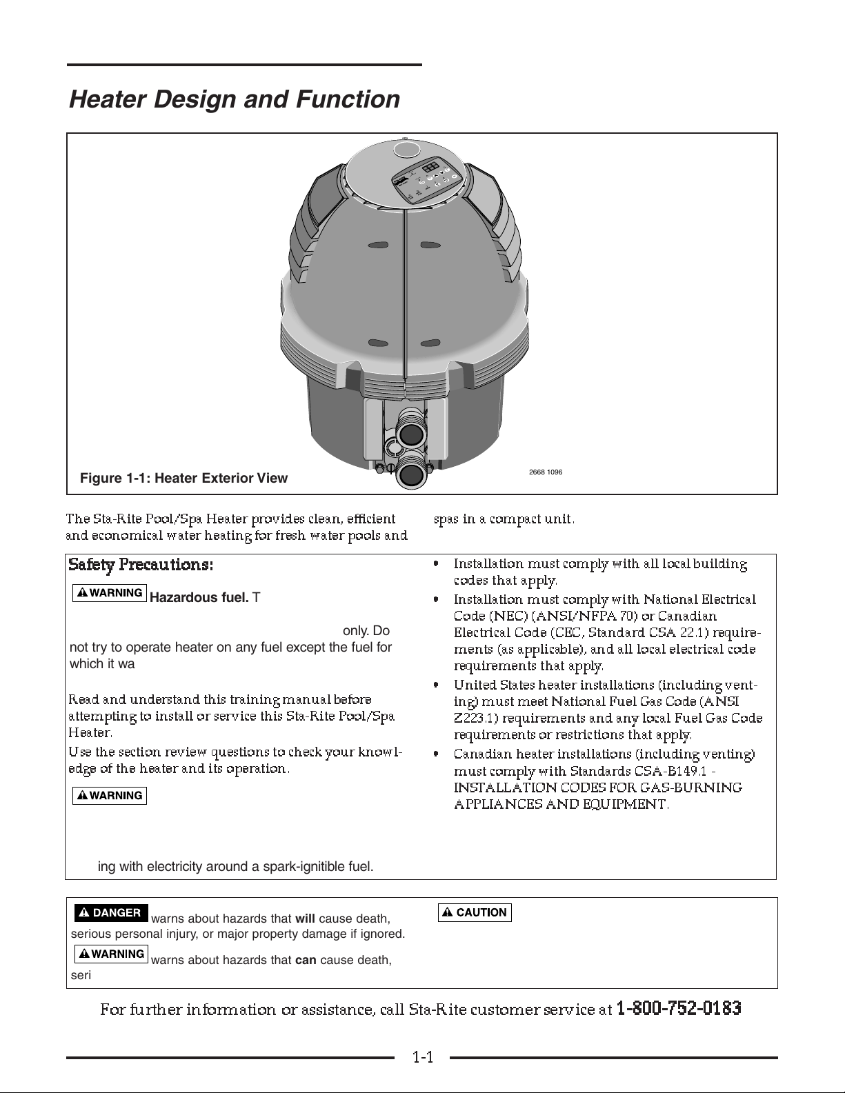
This heater is designed for use in heating fresh-water
swimming pools or spas. Do not use this heater as a
heating boiler or water heater, or for heating saltwater
pools.
CC
CCoo
oodd
ddee
ee AA
AAcc
cccc
ccoo
oorr
rrdd
ddaa
aann
nncc
ccee
ee
Installation in the U.S. must be in accordance with all
local codes, or, in the absence of local codes, with the
latest edition of the National Fuel Gas Code,
ANSI Z223.1, and the National Electrical Code,
ANSI/NFPA 70.
Installation in Canada must be in accordance with all local
codes, and with Standards CSA-B149.1 - INSTALLATION
CODES FOR GAS-BURNING APPLIANCES AND
EQUIPMENT.
HH
HHee
eeaa
aatt
ttee
eerr
rr LL
LLoo
oocc
ccaa
aatt
ttii
iioo
oonn
nn
Do not install the heater within five feet of the inside
surface of a pool or spa unless the heater is separated
from the pool or spa by a solid fence, wall or other per-
manent barrier.
Orient the heater for convenient access to gas, electrical
and water connections.
VV
VV
ee
eenn
nntt
ttii
iinn
nngg
gg RR
RRee
eeqq
qquu
uuii
iirr
rree
eemm
mmee
eenn
nntt
ttss
ss
The heater is supplied with an integral venting system
for outdoor installation. In the U.S., vent conversion
kits are available for indoor installations. Do not use a
draft hood with this heater. See Pages 2-3 through 2-11
for venting information.
GG
GGaa
aass
ss CC
CCoo
oonn
nnnn
nnee
eecc
cctt
ttii
iioo
oonn
nnss
ss
Heater Models SR200NA, SRC200NA, SR333NA,
SRC333NA, SR400NA, SR400HD, and SRC400NA,
leave the factory equipped to use natural gas. Heater
Models SR200LP, SRC200LP, SR333LP, SRC333LP,
SR400LP, and SRC400LP leave the factory equipped to
use liquid propane (LP) gas. In the field, refer to the
nameplate on the heater for the type of gas the heater is
equipped to use.
See Pages 4-17 and 4-18 of this Training Manual for
general instructions on replacing the orifice. Use only
factory authorized replacement parts for fuel conver-
sions. See Repair Parts, Page 5-3, for information on
Gas Orifice Kits. Follow instructions included with
Conversion Kits when converting the heater from nat-
ural gas to Propane or vice versa.
2-1
Heater Installation
SS
SSaa
aaff
ffee
eett
ttyy
yy PP
PPrr
rree
eecc
ccaa
aauu
uutt
ttii
iioo
oonn
nnss
ss::::
Explosion hazard. Improper installa-
tion, service or maintenance can cause an explo-
sion or fire resulting in death, serious injury or
property damage.
Warranty is void if heater has been improperly
installed, serviced, or maintained.
Explosion hazard with Propane gas
heaters. Propane gas is heavier than air and will
settle to the ground or floor. Do not install a
heater using Propane gas in pits or other loca-
tions where gas might collect. Follow the require-
ments for heater location as specified by the Standard
for Storage and Handling of Liquifed Petroleum
Gases, ANSI/NFPA 58 (latest edition) so that the
heater is installed a safe distance from Propane gas
storage and filling equipment.

SECTION TWO – Heater Installation
The heater can be used to heat either pools or spas. A
typical installation is shown above.
NN
NNOO
OOTT
TTEE
EE that the heater is downstream from the filter.
Also, the Chemical Feeder (Sanitizer) should be
installed as far downstream from the heater as possible.
Keep the number of elbows and fittings in the plumb-
ing to a minimum.
Install a chemical resistant, positive stop check valve
between the heater and the chemical feeder.
Pool/Spa Sizing
The Sta-Rite heater is available in three input ratings:
MM
MMoo
oodd
ddee
eell
ll RR
RRaa
aatt
ttii
iinn
nngg
gg
• SR/SRC200NA, SR/SRC200LP 200,000 BTUs/Hr
• SR/SRC333NA, SR/SRC333LP 333,000 BTUs/Hr
• SR/SRC400NA, SR/SRC400LP 400,000 BTUs/Hr
• SR400HD 400,000 BTUs/Hr
Use the tables below to determine the correct model
size for a particular pool or spa.
2-2
Cool Water
In From Spa
2735 1296
From Filter Outlet
to Heater
Inlet
Warm Water
Out to Pool or Spa
Sanitizer
Corrosion Resistant,
Positive Seal
Check Valve
To Filter
Inlet
Cool Water
In From Pool
To Spa
To Pool
SYSTEM 3™
Modular Media
Filter
Typical Installation
Figure 2-1: Typical Installation
Table 2-A: Maximum Pool Size in Sq. Ft. for a
Given Model Heater and a Given
Temperature Rise/24 Hr.
Table 2-B: Minutes For 30° F (11.4° C)
Temperature Rise
MODEL NUMBER
Temp. SR400NA
Diff. SR200NA SR333NA SR400LP
°F (C°) SR200LP SR333LP SR400HD
15 (8.3) 400 700 900
20 (11.1) 350 550 700
25 (13.9) 250 450 550
30 (16.7) 200 350 450
35 (19.4) 200 300 400
MODEL NUMBER
Spa SR400NA
Size SR200NA SR333NA SR400LP
Gal.(L) SR200LP SR333LP SR400HD
200 (757) 18 11 9
300 (1,136) 27 16 13
400 (1,514) 35 21 18
500 (1,893) 44 27 22
600 (2,271) 53 32 27
700 (2,650) 62 37 31
800 (3,028) 71 43 35
900 (3,407) 80 48 40
1,000 (3,785) 89 53 44
Recommended models for pools.
Recommended models for spas.

SECTION TWO – Heater Installation
Heater Placement and
Clearances
The heater must be at least five feet from the pool or
spa unless there is a solid barrier between the heater
and the pool or spa. In Canada, the heater must be at
least 18” from any property line.
Outdoor Installation
For heaters located outdoors, using the built-in stack-
less venting system.
HH
HHee
eeaa
aatt
ttee
eerr
rr CC
CCll
llee
eeaa
aarr
rraa
aann
nncc
ccee
eess
ss
There are two reasons for the clearances given here.
They are:
1. Adequate clearance from combustibles to avoid a
fire hazard.
2. Adequate air circulation around the heater to avoid
overheating.
Adequate working room for ease of maintenace will
depend on the installation.
Locate the heater on a level surface in an open,
unroofed area that is protected from drainage or run-
off. Install the heater in an area where leaves or other
debris will not collect on or around the heater. Do not
install the heater where water (including rain, sprin-
klers, or runoff) will fall directly onto the heater jacket.
2-3
1' Min.
4' Min.
4' Min.
4' Min.
3' Minimum clearance if
horizontal distance to
exhaust opening is less
than 10 feet.
Forced Air
Inlet
Installation Procedures
Figure 2-2: Clearance From Building Openings - U.S.
Outdoor installations
must have at least 3'
(1 M) of clearance
above vent.
leave 6 in.
(15 cm) of clear
space between
unit and
combustible
surfaces
TOP VIEW
6"
(15 cm)
3' (1M) or more
Space around unit must be open
on three sides when under roof
or overhang.
Figure 2-3: Combustion Clearances
SS
SSaa
aaff
ffee
eett
ttyy
yy PP
PPrr
rree
eecc
ccaa
aauu
uutt
ttii
iioo
oonn
nnss
ss::::
Fire hazard. The minimum clearance to
combustible surfaces is 6 inches.

SECTION TWO – Heater Installation
Outdoor Installation
If the heater is located under a roof or deck overhang,
there must be at least three feet (3’) clear space (U.S.) or
four feet (4’) clear space (Canada) between the bottom
of the overhang and the top of the heater exhaust vent,
and the space around the heater must be open on three
sides.
UU
UU....SS
SS....:::: The vent terminal opening must be located fur-
ther than four (4) feet below, four (4) feet horizontally,
and one (1) foot above any door, window, or gravity
inlet to a building. The vent terminal opening must be
further than three (3) feet above any forced air inlet
located within ten (10) feet horizontally. The exhaust
from the heater may cause discoloration of painted sur-
faces in close proximity (see Figure 2-2).
CC
CCaa
aann
nnaa
aadd
ddaa
aa:::: The heater must not be installed with the top
of the vent assembly within ten (10’) feet below, or to
either side of, any opening into a building.
The heater is certified for installation on combustible
flooring.
The following clearances must be maintained from
combustible surfaces:
UU
UU....SS
SS....::::
TT
TTOO
OOPP
PP OPEN
AA
AALL
LLLL
LL SS
SSII
IIDD
DDEE
EESS
SS 6 INCHES
OO
OORR
RR::::
TT
TTOO
OOPP
PP 3 FEET
11
11 SS
SSII
IIDD
DDEE
EE 6 INCHES
OO
OOTT
TTHH
HHEE
EERR
RR 33
33 SS
SSII
IIDD
DDEE
EESS
SS OPEN
CC
CCaa
aann
nna
a
aadd
ddaa
aa::::
TT
TTOO
OOPP
PP 4 FEET (1.2 M)
AA
AALL
LLLL
LL SS
SSII
IIDD
DDEE
EESS
SS 6 INCHES (15 cm)
If the heater is under a roof or deck overhang, the space
around the heater must be open on three sides.
Orient the heater for convenient access to the water
connections and to the gas and electrical connections
(below the vent terminal).
The exhaust discharges vertically from the vent. Make
sure that the control panel is not over the exhaust (see
next paragraph).
The heater control panel assembly on top of the jacket
can be turned to any of six positions for convenient
access to the Operating Control panel as follows:
1. Unbolt and separate the jacket halves.
2. Pull the hairpin clips (see Figure 2-4).
3. Depress plastic clips on the control panel assembly
and lift panel off of support plate. (see Figure 2-4).
4. Turn the control panel to the desired position and
snap it in place.
5. Make sure that the operating controls can be
adjusted without having to lean over the
exhaust vent. If necessary, reorient heater to sepa-
rate operating controls and exhaust.
6. Replace the hairpin clips.
7. Replace jacket halves and bolts and tighten.
2-4
4
5
1
2
2732 1296
FILTER
PUMP
AUX
1
AUX
2
HIGHSPEED
LOWSPEED
BOOSTERPUMP
3
Heater Placement, Clearances, and Venting
Figure 2-4: Indexing Control Panel
SS
SSaa
aaff
ffee
eett
ttyy
yy PP
PPrr
rree
eecc
ccaa
aauu
uutt
ttii
iioo
oonn
nnss
ss::::
Risk of explosion if a Propane gas unit is
installed in a pit or other low spot. Propane gas is heavier
than air. Do not install the heater using Propane gas in pits
or other locations where gas might collect. Consult your local
building code officials to determine installation requirements
of heater relative to Propane gas storage tanks and filling
equipment. Installation must meet National Fuel Gas Code
requirements. Consult local codes and fire protection authori-
ties about specific installation restrictions.
Risk of fire and explosion if installed at
floor level in an automotive garage or near gasoline or
flammable liquid storage. In a utility room or residential
garage, install the heater with the base at least 18” above the
floor so that the bottom of the combustion chamber and ignit-
er will be at least 20” off the floor.
Risk of asphyxiation if exhaust is not cor-
rectly vented. Follow venting instructions exactly when
installing heater. Do not use a draft hood with this
heater.
Risk of carbon monoxide poisoning. DO
NOT operate heater if vent faults are detected. Correct
any vent faults before operating heater.

SECTION TWO – Heater Installation
Indoor (U.S.) and Outdoor
Shelter (Canada) Installation
Instructions
The heater is design certified by CSA for installation on
combustible flooring; in alcoves; in basements; in clos-
ets or utility rooms (in the U.S.).
In Canada, this pool heater can only be installed out-
doors or in an enclosure (“outdoor shelter”) that is not
normally occupied and does not directly communicate
with occupied areas.
For installation on carpeting, the heater must be mount-
ed on a metal or wood panel that extends at least three
inches (10 cm) beyond the base of the heater. If the
heater is installed in a closet or alcove, the entire floor
must be covered by the panel.
Explosion hazard with Propane gas
heaters. Propane gas is heavier than air and will
settle to the ground or floor. Do not install a heater
using Propane gas in pits or other locations where
gas might collect. Follow the requirements for heater
location as specified by the Standard for Storage and
Handling of Liquifed Petroleum Gases, ANSI/NFPA 58
(latest edition) so that the heater is installed a safe dis-
tance from Propane gas storage and filling equipment.
II
IInn
nnss
sstt
ttaa
aall
llll
llaa
aatt
ttii
iioo
oonn
nn ii
iinn
nn aa
aa GG
GGaa
aarr
rraa
aagg
ggee
ee oo
oorr
rr UU
UUtt
ttii
iill
llii
iitt
ttyy
yy RR
RRoo
oooo
oomm
mm
Risk of fire and explosion if installed at
floor level in an automotive garage or near gasoline
or flammable liquid storage. Gasoline fumes are
heavier than air and will settle to floor level in closed
spaces. Gasoline fumes and spilled gasoline or other
volatile liquids (such as some paints and varnishes)
will travel across the floor and can be ignited by a gas
appliance. In a utility room or residential garage installa-
tion, install the heater with the base at least 18 inches
above the floor, so that the burner and ignition device
will be at least 20 inches above the floor (see Figure
2-5). In a garage, install a rail or wall to protect the
heater from physical damage by a moving vehicle.
HH
HHee
eeaa
aatt
ttee
eerr
rr CC
CCll
llee
eeaa
aarr
rraa
aann
nncc
ccee
eess
ss
II
IInn
nndd
ddoo
oooo
oorr
rr ((
((UU
U
U....SS
SS....))
)) oo
oorr
rr OO
OOuu
uutt
ttdd
ddoo
oooo
oorr
rr SS
SShh
hhee
eell
lltt
ttee
eerr
rr ((
((CC
CCaa
aann
nnaa
aadd
ddaa
aa))
))
The following clearances must be maintained from
combustible surfaces:
TT
TTOO
OOPP
PP 6 INCHES
AA
AALL
LLLL
LL SS
SSII
IIDD
DDEE
EESS
SS 6 INCHES
VV
VVEE
EENN
NNTT
TT 6 INCHES
VV
VV
ee
eenn
nntt
ttii
iinn
nngg
gg II
IInn
nndd
ddoo
oooo
oorr
rr aa
aann
nndd
dd OO
OOuu
uutt
ttdd
ddoo
oooo
oorr
rr SS
SShh
hhee
eell
lltt
ttee
eerr
rr
II
IInn
nnss
sstt
ttaa
aall
llll
llaa
aatt
ttii
iioo
oonn
nnss
ss
Risk of asphyxiation if exhaust is not
correctly vented. Follow venting instructions exact-
ly when installing heater. Do not use a draft hood
with this heater, as the exhaust is under pressure from
the burner blower and a draft hood will allow exhaust
fumes to blow into the room housing the heater.
Exhaust venting to the outdoors is required for all
indoor and outdoor shelter (“enclosed”) installations.
DO NOT common vent this heater with another
appliance.
DO NOT substitute or modify parts in the venting
system.
Enclosed installation requires venting to the outside.
On an enclosed installation, the exhaust discharges
from the Vent Body into a vent pipe. Locate the heater
so the vent run is as short and straight as possible.
Orient the heater so that the vent pipe does not inter-
fere with adjustment of the operating controls. The
operating control panel located on top of the jacket can
be rotated for easy access.
2-5
Heater Placement, Clearances, and Venting
6 in. (15 cm)
clear space
above
leave 6 in.
(15 cm) of
clear space
between
unit and
combustible
surfaces
TOP VIEW
6"
(15 cm)
Raise at least 18"
(.5 M) above floor
to avoid flammable
vapors
18" (.5 M)
Figure 2-5: Minimum Indoor Clearances
SS
SSaa
aaff
ffee
eett
ttyy
yy PP
PPrr
rree
eecc
ccaa
aauu
uutt
ttii
iioo
oonn
nnss
ss::::
Risk of carbon monoxide poisoning.
DO NOT operate heater if vent faults are detected.
Correct any vent faults before operating heater.

SECTION TWO – Heater Installation
VV
VV
ee
eenn
nntt
ttii
iinn
nngg
gg II
IInn
nndd
ddoo
oooo
oorr
rr aa
aann
nndd
dd OO
OOuu
uutt
ttdd
ddoo
oooo
oorr
r
rSS
SShh
hhee
eell
lltt
ttee
eerr
rr
II
IInn
nnss
sstt
ttaa
aall
llll
llaa
aatt
ttii
iioo
oonn
nnss
ss ––
–– CC
CCoo
o
onn
nntt
ttii
iinn
nnuu
uuee
eedd
dd
The heater requires sufficient air for combustion and
ventilation. Choose a location that will avoid contami-
nation by chemical fumes.
NN
NNOO
OOTT
TTEE
EE:::: Combustion air contaminated by corrosive
chemical fumes can damage the heater and will void
the warranty.
Combustion and Ventilation
Air Supply
For indoor installation, the heater requires air supply
openings for ventilation and combustion. The mini-
mum requirements are for two (2) openings: one 12
inches from the ceiling for ventilation air and one 12
inches from the floor for combustion air, in accordance
with the latest edition of the National Fuel Gas Code,
ANSI Z223.1., and any local codes that may apply.
The minimum net free area in square inches shall be
as follows:
Table 2-D: Combustion and Ventilation
Air Requirements
Indoor Vent Installation
Always vent the heater to the outdoors.
• Vent it horizontally or vertically using Special Gas
Vent, (see Table 2-G, Page 2-10), or
• Vent it vertically using Type “B” double wall vent
connector pipe.
Locate the heater so as to minimize the length of hori-
zontal vent pipe and the number of vent elbows
required. Horizontal vent runs must slope up 1/4"per
foot from the heater to allow exhaust condensate to
drain and must have a condensate drain as described in
the venting installation instructions.
OO
OOuu
uutt
ttdd
ddoo
oooo
oorr
rr VV
VVee
eenn
nntt
tt CC
CCoo
oovv
vvee
eerr
rr RR
RRee
eemm
mmoo
oovv
vvaa
aall
ll
The heater is supplied from the factory with a built-in
stackless outdoor vent for outdoor installation. Remove
the outdoor Vent Cover for enclosed installation. To
reinstall the outdoor Vent Cover, hold it in place against
the Vent Body,push together, and fasten with two
screws.
2-6
Heater Venting
Area Likely Contaminants
Chlorinated swimming Pool or spa cleaning
pools and spas chemicals. Acids, such as
hydrochloric or muriatic acid
New construction and Glues and cements,
remodeling areas construction adhesives,
paints, varnishes, and
paint and varnish strippers.
Waxes and cleaners
containing calcium or
sodium chloride
Beauty parlors Permanent wave solutions,
bleaches, aerosol cans
containing chlorocarbons
or fluorocarbons
Refrigeration plants or Refrigerants, acids, glues
various industrial and cements, construction
finishing and adhesives
processing plants
Dry cleaning and Bleaches, detergents, or
laundry areas laundry soaps containing
chlorine.
Waxes and cleaners
containing chlorine,
calcium or sodium chloride
Table 2-C: Corrosive Vapors and Possible Sources
All Air From All Air From
Inside Building Outside Building
Model Combustion Vent Combustion Vent
200 200 in2200 in250 in250 in2
1,291 cm21,291 cm2323 cm2323 cm2
333 333 in2333 in284 in284 in2
2,149 cm22,149 cm2542 cm2542 cm2
400 400 in2400 in2100 in2100 in2
2,581 cm22,581 cm2645 cm2645 cm2

SECTION TWO – Heater Installation
Figure 2-6: Flue collar
VV
VV
ee
eerr
rrtt
ttii
iicc
ccaa
aall
ll VV
VVee
eenn
nntt
ttii
iinn
nngg
gg --
-- NN
NNee
eegg
ggaa
aatt
ttii
iivv
vvee
ee PP
PPrr
rree
eess
ssss
ssuu
uurr
rree
ee
((
((SS
SSee
eeee
ee FF
FFii
iigg
gguu
uurr
rree
ee 22
22--
--77
77)
)
))
Vent the heater vertically in a negative pressure (posi-
tive draft) system in accordance with the National Fuel
Gas Code, ANSI Z223.1, and local codes. Class “B”
Double-wall vent connector is recommended; however
single-wall pipe is allowed by the National Fuel Gas
Code in some circumstances. Consult your local code
official for detailed information.
Risk of asphyxiation. Do not use a draft
hood with this heater.
To connect a negative pressure metal gas vent to the
heater, order the appropriate Metal Flue Collar from
thechart below:
Metal Flue Collar Kit Sta-Rite Part No.
4x6” 77707-0076
4x8” 77707-0077
1. See Table 2-E, below, to determine allowable vent
sizes for your heater.
NN
NNOO
OOTT
TTEE
EE:::: Table 2-E is for installations in which the total
lateral vent length (that is, the horizontal distance from
the Metal Flue Collar to the main vertical portion of the
vent) is less than 1/2 the total vent height (the vertical
distance from the flue collar to the vent termination)
and which have three or less elbows in the system. For
venting systems which do not meet these conditions,
consult the National Fuel Gas Code, ANSI Z223.1 (U.S.)
and CSA-B149.1 (Canada).
2-7
Heater Venting – Negative Pressure
Combustion
Chamber
Flue Collar
4" x 8" Metal
Flue Collar
Vent Body
2855 0597 RTV
Clean the Interior Surface
Vent Pipe
Clean and RTV
This Surface
Table 2-E: Permitted Minimum and Maximum Vent Heights By Size and Heater Model
Read “VERTICAL VENTING – NEGATIVE PRESSURE” (above) before using this table.
Type B Double Wall Vent With Type B Double Wall Connector In Feet (Meters)
Model 200 Model 333 Model 400
Vent Size Min. Height Max. Height Min. Height Max. Height Min. Height Max. Height
6 in. 6 Ft. (1.8) 100 Ft. (30.5) 30 Ft. (9.0) 100 Ft. (30.5) Not Rec. Not Rec.
7 in. 6 Ft. (1.8) 100 Ft. (30.5) 10 Ft. (3.0) 100 Ft. (30.5) 15 Ft. (4.6) 100 Ft. (30.5)
8 in. 6 Ft. (1.8) 100 Ft. (30.5) 6 Ft. (1.8) 100 Ft. (30.5) 8 Ft. (2.4) 100 Ft. (30.5)
9 and 10 in. 6 Ft. (1.8) 50 Ft. (15.3) 6 Ft. (1.8) 100 Ft. (30.5) 6 Ft. (1.8) 100 Ft. (30.5)
Type B Double Wall Vent With Single Wall Connector In Feet (Meters)s
Model 200 Model 333 Model 400
Vent Size Min. Height Max. Height Min. Height Max. Height Min. Height Max. Height
6 in. 6 Ft. (1.8) 15 Ft. (4.6) Not Rec. Not Rec. Not Rec. Not Rec.
7 in. 6 Ft. (1.8) 8 Ft. (2.4) 10 Ft. (3.0) 20 Ft. (6.0) 15 Ft. (4.6) 50 Ft. (15.3)
8 in. Not Rec. Not Rec. 6 Ft. (1.8) 20 Ft. (6.0) 8 Ft. (2.4) 20 Ft. (6.0)
9 in. Not Rec. Not Rec. Not Rec. Not Rec. 6 Ft. (1.8) 6 Ft. (1.8)
10 in. Not Rec. Not Rec. Not Rec. Not Rec. Not Rec. Not Rec.

SECTION TWO – Heater Installation
2. Install the metal Flue Collar in the Vent Body of
the heater (located under the outside vent cover).
Fasten the metal Flue Collar to the Vent Body with
two #10 sheet metal screws. Use UltraCopper®sili-
cone RTV to seal the metal Flue Collar to the Vent
Body. Follow instructions supplied with the metal
Flue Collar. Before connecting the metal Flue
Collar to the Vent Body, wet a clean cloth or paper
towel with isopropyl alcohol (rubbing alcohol) and
vigorously wipe the socket of the Vent Body.
Immediately wipe the cleaned surfaces dry with a
clean cloth or paper towel. Repeat for the exterior
of the 4” end of the metal Flue Collar. Attach the
metal Flue Collar to the Vent Body using the RTV
supplied with the kit, following the instructions
included with kit. DD
DDoo
oo nn
nnoo
oott
tt use a draft hood with
this heater.
3. Attach the vent pipe to the Metal Flue Collar with
sheet-metal screws.
Risk of fire or asphyxiation if vent is
not assembled according to manufacturer’s instruc-
tions or if vent parts from different manufacturers
are mixed. Vent parts from different manufacturers
ARE NOT interchangeable. Mixing parts from more than
one manufacturer may cause leaks or damage to vent.
When assembling a vent, pick one manufacturer and be
sure that all vent parts come from that manufacturer
and are specified by the manufacturer for your system.
Follow manufacturer’s instructions and local and
National Fuel Gas Code requirements carefully during
assembly and installation.
4. Install vent pipe so that it can expand and contract
freely as the temperature changes. Support the vent
pipe according to applicable codes and the vent
manufacturer’s instructions. Pipe support must
allow the vent pipe free movement out and back,
from side to side, or up and down as necessary,
without putting a strain on the heater or vent body.
Slope horizontal pipe runs up from the heater at
least 1/4"per foot (2 cm/meter). Install Listed con-
densate drains at low points where condensate
might collect. Plumb condensate drains to a drain
through hard piping or high-temperature tubing
such as silicone rubber or EPDM rubber – do not
use vinyl or other low temperature tubing. Follow
drain manufacturer’s installation instructions.
5. Use Listed firestops for floor and ceiling penetra-
tions. Use Listed thimble for wall penetrations. Use
a Listed roof flashing, roof jack, or roof thimble for
all roof penetrations. Do not fill the space around
the vent (that is, the clear air space in the thimble
or firestop) with insulation. The roof opening must
be located so that the vent is vertical.
6. See Table 2-F (Page 2-7) for height of vent termina-
tion above the roof (U.S.) and Figure 2-7 (Page 2-7)
for U.S. venting requirements. See Figure 2-8 (Page
2-7) and Standard CSA-B149.1 for Canadian vent-
ing requirements.
7. Do not run the heater vent into a common vent
with any other appliance.
Fire Hazard. Do not vent the heater
directly into a masonry chimney. Installation into a
masonry chimney must use a chimney liner and must
meet National Fuel Gas Code requirements and all
local code requirements.
2-8
Heater Venting – Negative Pressure

SECTION TWO – Heater Installation
Table 2-F: Vent Termination Height
vs. Roof Pitch - U.S.
FIGURE 2-7: Typical Metal Vent Pipe Installation
(Vertical – Negative Pressure) - U.S. Standards
If corrosion is a problem in your area, consider
installing a condensate drain with a trap.
FIGURE 2-8: Typical Metal Vent Pipe Installation
(Vertical – Negative Pressure) - Canadian Standards
2-9
Heater Venting – Negative Pressure
Minimum Height
Roof Pitch Above Roof*
Flat to 6/12 1 Ft.
6/12 to 7/12 1 Ft. 3 in.
>7/12 to 8/12 1 Ft. 6 in.
>8/12 to 9/12 2 Ft.
>9/12 to 10/12 2 Ft. 6 in.
>10/12 to 11/12 3 Ft. 4 in.
>11/12 to 12/12 4 Ft.
>12/12 to 14/12 5 Ft.
>14/12 to 16/12 6 Ft.
>16/12 to 18/12 7 Ft.
>18/12 to 20/12 7 Ft. 6 in.
>20/12 to 21/12 8 Ft.
* Vent must be at least eight (8) feet away from nearest verti-
cal surface. Vents extending five (5) feet or more above the
roof must be braced or guyed. Consult your local code officials
for detailed information.
6" Minimum
Clearance to
Combustible
Materials
Listed
Termination
Cap
Storm Collar
Flashing
Firestop
Vent
Body
Metal Flue
Collar
Class B Double Wall
Metal Vent Pipe
See Table 4
For Min. Hght.
Min. 8 Ft.
Support Vertical
Vent Pipe so
adapter does not
take weight of
pipe.
6" (15 cm) Minimum
Clearance to Combustible
Materials
Listed
Termination
Cap
Storm Collar
Flashing
Firestop
Vent
Body
Metal Flue
Collar
Type B Double Wall
Metal Vent Pipe
2731 1296 CAN
Min. 10 Ft. (3.3 M)
Support Vertical
Vent Pipe so
adapter does not
take weight of
pipe. Dispose
of condensate
according to
local codes.
Type B Double Wall
Metal Vent Tee
Condensate
Drain w/trap
Min. 2 Ft.
(.7 M)

SECTION TWO – Heater Installation
HH
HHoo
oorr
rrii
iizz
zzoo
oonn
nntt
ttaa
aall
ll oo
oorr
rr VV
VVee
eerr
rrtt
ttii
iicc
ccaa
aall
ll VV
VVee
eenn
nntt
ttii
iinn
nngg
gg --
-- PP
PPoo
ooss
ssii
iitt
ttii
iivv
vvee
ee
PP
PPrr
rree
eess
ssss
ssuu
uurr
rree
ee (See Figures 2-9, 2-10 and 2-11)
Vent the heater either horizontally or vertically using
one of the 4-inch Special Gas Vent Pipes listed on Page
2-10 (Table 2-G). Install the vent pipe in accordance
with local codes and the provisions of the National Fuel
Gas Code, ANSI Z223.1 (U.S.) or Standard CSA-B149.1
(Canada), and the vent manufacturer’s instructions.
DD
DDoo
oo nn
nnoo
oott
tt use a draft hood with this heater. Use one of the
special gas vents specified in Table 2-G (Page 2-11) for
positive-pressure venting of this heater – do not use
any other vent with it. Install the vent according to the
vent manufacturer’s detailed instructions.
Maintain clearance between the vent pipe and com-
bustible surfaces according to the vent manufacturer’s
instructions and code requirements. Do not place any
insulating materials around the vent or inside the
required clear air space surrounding the vent. See Table
2-H (Page 2-12) for maximum permissable vent lengths.
See Table 2-J (Page 2-12) for vent thimbles and termi-
nals listed in U.S.
CC
CCoo
oonn
nnnn
nnee
eecc
cctt
ttii
iinn
nngg
gg SS
SSpp
ppee
eecc
ccii
iiaa
aall
ll GG
GGaa
aass
ss VV
VVee
eenn
nntt
tt tt
ttoo
oo tt
tthh
hhee
ee HH
HHee
eeaa
aatt
ttee
eerr
rr
MM
MMee
eett
ttaa
aall
llll
llii
iicc
cc::::
1. Order an Appliance Adapter Kit:
Sta-Rite Part No. 77707-0086 for Saf-T Vent® or
Saf-T Vent® CI.
Sta-Rite Part No. 77707-0087 for Z-Vent.
2. Remove the outside Vent Cover.
SS
SSuu
uurr
rrff
ffaa
aacc
ccee
ee PP
PPrr
rree
eepp
ppaa
aarr
rraa
aatt
ttii
iioo
oonn
nn::::
3. Install the Appliance Adapter in the Vent Body of
the heater (located under the outside Vent Cover).
Before connecting the Appliance Adapter to the
Vent Body, wet a clean cloth or paper towel with
isopropyl alcohol (rubbing alcohol) and vigorously
wipe the socket of the Vent Body. Immediately
2-10
Heater Venting – Positive Pressure
1' Min.
4' Min.
4' Min.
4' Min.
4' Min.
3' Minimum clearance if
horizontal distance to
exhaust opening is less
than 10 feet.
Forced Air
Inlet
Vent
Termination
1' Minimum
above snow or
finished grade
(whichever is
higher)
At least 7'
above grade
adjacent
to public
walkways
Vent
Termination Vent
Termination
Gas Meter
Max 12"
Min 3"
FIGURE 2-10: Minimum Clearances for Vent Termination - U.S.
Combustion
Chamber
Flue Collar
Metal 4" Z-Flex
Adapter (Line up
Ridge with tip
of Vent Body)
Vent Body
2856 0597RTV
Clean and RTV
This Surface
Clean the Interior Surface
Figure 2-9: Metal Appliance Adapter for Metallic
Special Gas Vent (4”)

SECTION TWO – Heater Installation
wipe the cleaned surfaces dry with a clean cloth or
paper towel. Repeat for the exterior of the heater
end of the Appliance Adapter. Attach the appliance
adapter to the vent body using the adhesive speci-
fied by the vent manufacturer, following the vent
manufacturer’s instructions.
Risk of carbon monoxide poisoning if
Appliance Adapter is improperly attached.
Mechanical connections (such as screws) can
cause cracking and leaks in the Adapter or Vent
Body. Do not drill holes or use screws to connect the
Appliance Adapter to the heater Vent Body. Attach with
the adhesive that is supplied with the Appliance
Adapter Kit.
Risk of fire or asphyxiation if vent is
not assembled according to manufacturer’s
instructions or if vent parts from different manu-
facturers are mixed. Vent parts from different manu-
facturers ARE NOT interchangeable. Mixing parts from
more than one manufacturer may cause leaks or dam-
age to vent. When assembling a vent, pick one manu-
facturer and be sure that all vent parts come from that
manufacturer and are specified by the manufacturer for
your system. Follow manufacturer’s instructions and
local and National Fuel Gas Code requirements care-
fully during assembly and installation.
4. Install vent pipe so that it can expand and contract
freely as the temperature changes. Support the
vent pipe according to applicable codes and vent
manufacturer’s instructions. Pipe support must
allow the vent pipe free movement out and back,
from side to side, or up and down as necessary,
without putting a strain on the heater or Vent
Body. Slope horizontal pipe runs up from the
heater at least 1/4” per foot. Install Listed conden-
sate drains at low points where condensate might
collect. Plumb condensate drains to a drain
through hard piping or high-temperature tubing
such as silicone rubber or EPDM rubber – do not
use vinyl or other low temperature tubing. Follow
drain manufacturer’s installation instructions.
5. Use Listed firestops for floor and ceiling penetra-
tions. Use Listed thimble for wall penetrations. Use
a Listed roof flashing, roof jack, or roof thimble for
all roof penetrations. Do not fill the space around
the vent (that is, the clear air space in the thimble
or firestop) with insulation. The roof opening must
be located so that the vent is vertical.
6. Vent Termination – Vertical (See Table 2-F, Page
2-9, for height of vent termination above the roof
in the U.S. See Table 2-J, Page 2-12, for Listed ter-
minations.) Use a Listed vent terminal specified by
local and national codes and your manufacturer’s
instructions. A roof termination must be vertical.
In Canada, the Vent Cap location must have a min-
imum clearance of 4 feet (1.2 M) horizontally from
electric meters, gas meters, regulators, and relief
openings.
7. United States Vent Termination – Horizontal (See
Table 2-J). Use a listed wall thimble and vent termi-
nal from Table 2-J.
In the U.S. the terminal must be located
(see Figure 2-10, Page 2-10):
• at least 3"and at most 12" out from the wall (see
Figure 2-10), following the vent manufacturer’s
instructions.
• at least 12"above finished grade or the normally
expected snow accumulation level, whichever is
higher.
2-11
Heater Venting – Positive Pressure
Brand Manufacturer Material Type Sealant
Saf-T Vent®4” Heat-Fab, Inc. Metal Consult Manufacturer
Special Gas Vent 38 Hayward Street
(Single Wall) Greenfield, MA 01301
(800) 772-0739
Saf-T CI Vent®Heat-Fab, Inc. Metal Consult Manufacturer
Special Gas Vent 38 Hayward Street
(Double Wall) Greenfield, MA 01301
(800) 772-0739
Z-Vent 4” Special Z-Flex U.S., Inc. Metal G.E. RTV 106
Gas Vent (Type BH), 20 Commerce Park North
Model SVE Bedrford, NH 03110-6911
(800) 654-5600
Table 2-G: Recommended Special Gas Vents (Positive Pressure)
This manual suits for next models
12
Table of contents
Other STA-RITE Heater manuals
Popular Heater manuals by other brands

islandspring
islandspring IS-HEAT-LED Operating/safety instructions

Euromatic
Euromatic JCPH-1000 instruction manual

Thermo-bug
Thermo-bug basic 3.0 operating instructions

Farenheit
Farenheit THSR-68SV owner's manual

Dimplex
Dimplex XLS quick start guide

Mestek
Mestek SEPARATED COMBUSTION GAS FIRED PROPELLER UNIT... Installation instructions & parts list