STA-RITE Calypso GW7000 User manual

CalypsoTM Pool Cleaner
O W N E R’ S M A N U A L
INSTALLATION, OPERATION & PARTS
MODEL GW7000
Sta-Rite Pool/Spa Group
293 Wright Street, Delavan, WI 53115
International: 262-728-5551, FAX: 262-728-7550
www.starite.com
Union City, TN • Delavan, WI • Mississauga, Ont. • Murrieta, CA
© 2005, Sta-Rite Industries S790 (4/12/05)

2
PLEASE READ THE FOLLOWING
BEFORE INSTALLING YOUR
CALYPSO POOL CLEANER!
About Safety:
This is the safety alert symbol. When you see this
symbol on your system or in this manual, look for one of
the following signal words and be alert to the potential for
personal injury.
warns about hazards that will cause death,
serious personal injury, or major property damage if
ignored.
warns about hazards that can cause death,
serious personal injury, or major property damage if
ignored.
warns about hazards that will or can cause
minor personal injury or property damage if ignored.
Carefully read and follow all safety instructions in this
manual and on equipment. Keep safety labels in good con-
dition; replace if missing or damaged.
Congratulations on the purchase of your new Calypso au-
tomatic pool cleaner. This manual will guide you through
the steps needed to install and operate it. Please read it
carefully.
Hose can trip or entangle swimmers. Do not
allow swimmers in pool while cleaner is operating.
Flapper Valve may injure hands or fingers.
Stop pump before attempting to cleanout pool cleaner
head.
CONTENTS:
Prepare Your Pool ...........................................................2
Decide on the Suction Connection .................................2
Unpack and Assemble Your Calypso ...........................2-3
Install Your Calypso .....................................................4-6
Optimizing Performance..............................................6-7
Maintenance ...................................................................8
Troubleshooting .........................................................9-10
Parts and Disassembly..............................................11-14
Warranty .......................................................................15
PREPARE YOUR POOL
Before installing your Calypso, clean your filter system and
empty all leaf baskets. A clean filter system is necessary for
proper operation of automatic pool cleaners. It will also
lessen the load on your pump and reduce electricity and
pump repair bills.
Prepare your pool as follows:
1. Manually vacuum the pool
2. Brush the walls and other parts of the pool surface to
lift off grime and algae.
3. Clean the filter and remove debris from the pump trap
and skimmer baskets.
4. Chemically balance the pool water.
DECIDE ON THE SUCTION
CONNECTION
Suction entrapment, injury, and drowning
hazard. If your pool has a dedicated suction port (“vac
port”) for vacuuming or for an automatic pool cleaner, it
must be covered when not in use. A spring loaded safety
cover (a “vac port fitting”) is included with your cleaner.
Install it on the suction port to prevent entrapment and in-
jury. If the cover provided does not fit, purchase one that
does from your local pool store and install it instead. The
cover should conform to IAPMO SPS4-99A.
1. Decide on the suction connection you will use –
either a dedicated wall fitting or a skimmer.
2. Identify the filter valves that control water flow through
the intakes in your pool. When you install the Calypso
you will adjust the valves (if your system has valves) of
your pump/filter to draw the water through the chosen
connection.
UNPACK AND ASSEMBLE YOUR
CALYPSO (Figures 1 and 2)
1. Open the box and make sure that you have the follow-
ing items. Note that the Calypso’s unique bumper and
roller assembly may have been attached prior to ship-
ment. If it is not attached, follow the instructions to at-
tach it yourself.
Hazardous suction.
Can trap and tear
hair or body parts.
Can cause drowning.
Do not play with cleaner
or hose or apply to body.
Do not let children use or
play with pool cleaner.
Stop pump before
attempting to clean unit.
Do not allow swimmers in
pool while pool cleaner is
operating.

3
2. If not already done, attach the Bumper and Roller to
the flexible stalk protruding from the body of the
Calypso (See Figure 1A).
3. Attach the Pipe and Nut Assembly to the top (threaded)
end of the Calypso (See Figure 2A).
First place the collar of the Bumper and Roller assembly
over the threaded end of the Main Housing and then screw
on the Pipe and Nut Assembly as shown in Figure 2B.
When the Pipe and Nut Assembly is installed, the bumper
and roller won’t swing loosely from the cleaner.
Hand tighten the nut as if you were tightening the lid on a
kitchen container; you will occasionally need to unscrew
the Pipe and Nut Assembly to perform routine mainte-
nance on the cleaner.
Your Calypso cleaner is assembled!
Figure 2B
Figure 2A
Figure 1A - Cleaner body with
round vacuum plate attached
and Bumper/Roller attached.
Figure 1F - Hose Sections
(each section has one male
and one female end).
Figure 1L - Flow Gauge.
Figure 1E - Outlet Diverters.
Figure 1D - Bumper and Roller
(This may already be attached
to the cleaner body).
Figure 1C - Regulator Valve
and Cap.
Figure 1G - Adapter Cone. Figure 1H - Hose Weight.
Figure 1J - Ladder Deflector.
Vac
Port
Figure 1K - Vac Port Fitting.
Figure 1B - Pipe and Nut
Assembly (to attach to the
cleaner).

4
INSTALL YOUR CALYPSO
Step 1: Install Vacuum Port Door fitting
If there is no spring-loaded door on the vacuum port, in-
stall the included cover.
If your pool only has a skimmer, and no dedicated vac-
uum port, proceed to Step 3.
1. Screw the fitting into the port opening.
2. Orient the fitting so the arrow on the door point up.
3. Secure the cover by tightening the allen-screw below
the door.
Step 2: Install Regulator in Pools with a
Dedicated Vacuum Port
The pool regulator adjusts the amount of vacuum in the
line for optimum cleaning.
If your pool has a dedicated wall fitting in addition to the
skimmer, follow the procedure below.
1. Turn off the pool pump.
2. Place the regulator in the skimmer as shown. The cap
must be placed in the top
Use the adapter cone if needed.
3. Attach one length of hose to the vacuum port
Step 3: Pools with only a Skimmer
1. Turn off the pool pump.
2. Place the regulator in the skimmer as shown. Do not
install the cap.
Use the adapter cone if needed.
3. Submerge one length of hose so it becomes filled
with water.
4. Insert the “male” end of the hose into the regulator.
Figure 3 - Vacuum Port Installation.
Hose
End
Vac Port
Fitting
Figure 5 - Vacuum Port Connection.
Skimmer
Regulator
Cap
To Pump
Adapter Cone
Figure 4 - Regulator in Skimmer.
Skimmer
Regulator
To Pump
Adapter Cone
Figure 6 - Regulator in Skimmer.

5
Step 4: Connect the hose sections (Figures 9 and 10).
For best results and to retain your warranty, use only gen-
uine Calypso hoses.
Join the Calypso hose sections one to another by fitting the
male end to the female end of the added section (see
Figure 7). Make sure the connections are snug. The num-
ber of lengths that you will need depends on the size of
your pool.
The overall length of hose needed will be the distance
from:
(a) the point at which you will attach the hose to the suc-
tion connection, to (b) the furthest point in the pool from
(a), plus one hose length (Figure 8).
Submerge the hose so it fills with water and expels air from
the hose. Attach one ond of the hose to the vacuum source
as descrbed in Steps 2 and 3. Keep the other end of the
hose accessible.
Step 5: Adjust flow
1. Insert the flow gauge into the open end of the hose,
still underwater.
2. Start the pump.
3. Turn the adjustment knob on the flow regulator until
the indicator on the flow gauge is between the maxi-
mum and minimum flow (See Figure 9).
NOTE: If you have a very strong pump and the flow is
still too fast, slightly open the main drain.
4. Turn off the pump.
5. Remove the flow gauge and attache the hose to the
cleaner.
Step 6: Attach the female end of the hose to the
Calypso (see Figure 10).
Figure 7
Figure 8
ab
Disc Indicator
Figure 9 - Flow Indicated on Flow Gauge.
Figure 10

6
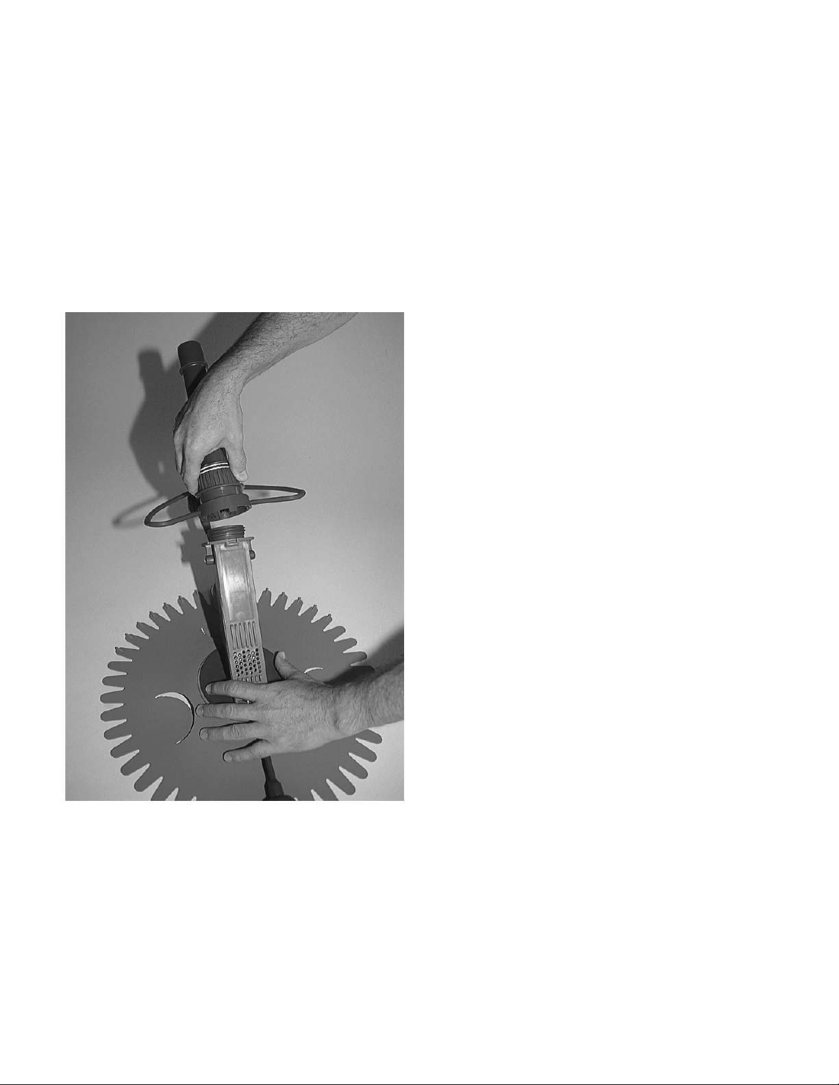
Step 7: Balancing the hose (Figure 12).
It may or may not be necessary to add weight to your hose,
depending on your pool’s size, shape, and depth. Try the
cleaner first without any hose weights. If the hose is too
buoyant, add the weight as shown in Figure 11.
Step 8: Start the filter system pump.
Start the pump and set the valves at the filter to draw most
of the water through the cleaner.
Close the main drain (floor drain) and any additional
skimmers.
Allow a few minutes to flush excess air from the system.
With water flowing properly through the system, the hose
and the Calypso cleaner will start to jerk. Your cleaner
should pull itself against the pool bottom and move across
it at a rate of 15 to 25 feet per minute.
OPTIMIZING PERFORMANCE
Hazardous suction. Can trap hair or body
and cause death or serious injury.
Do not fit parts to the suction intake while the filter
pump is running.
Be sure that you properly install the regulator valve
before you turn on the pump and fine-tune your cleaning
system. The valve acts as a safety device as well as regulat-
ing suction through the cleaner.
Check the Hose Length; Remove any Loops.
Using a pool brush and pole, gently pull the Calypso to the
area of the pool furthest from the vacuum connection.
Make sure that any loops in the hose are pulled out.
The hose should be just long enough to allow the Calypso
to clean this area. Remove or add a section of hose if
necessary.
Adjust Filtration System Valves.
You may need to do some adjusting of the filtration system
valves to optimize the water flow through the Calypso for
best cleaner operation.
NOTE: Optimizing the water flow does not mean maxi-
mizing the flow through the cleaner. In fact, to ensure a
random pattern of travel that will enable the Calypso to
reach all areas of your pool, it is better to use less suction,
not more.
• Turn on the pump.
• If you have not already done so, close the valve that
controls the flow through the main drain in the floor of
the pool.
• If your pool has a skimmer as well as a dedicated wall
fitting, or more than one skimmer, adjust the filter
valve/s so that most of the water will be drawn through
the Calypso. Make a note of which valves these are,
because if you have excessive flow through the
cleaner, you will need to reopen these valves some-
what in order to adjust the flow (See NOTE, above).
• Re-adjust flow as described in Step 5 on Page 5.
• With correct flow through the cleaner, your Calypso
should travel across the pool floor at 15 to 25 feet per
minute.
• If the transition from your pool’s floor to the wall will
allow it, your cleaner will climb up the wall, possibly
to the top, before turning towards the floor again. In
some cases, the cleaner will lose its grip on the wall
and fall back to the floor. This is normal – it is a char-
acteristic that assists the cleaner to form new cleaning
patterns, thus cleaning your pool more effectively. If
the cleaner hugs the walls or hugs the floor excessively,
you need to balance the hose.
• When cleaning walls the Calypso will occasionally de-
tach itself and fall to the pool floor. This is normal.
However, when the cleaner falls it should land on the
vacuum plate and then seal itself to the floor within 30
seconds. If the cleaner lands on a steeply sloped sec-
tion of the floor, the sealing process may take longer.
This too is normal.
CALYPSO cleaner
Attach the Hose Weight
1" back from the end of
the first hose section
Figure 11

7
Balancing the hose using the weight (Figure 12)
It is important to balance the hose so that it is only slightly
lighter than water. If the hose is too buoyant, the Calypso
will be pulled upward and outward towards the perimeter
of the pool and will not clean the deep end properly. If the
hose is not buoyant enough, it will drag along the pool
floor and impede the cleaning action, particularly of pool
walls.
It may or may not be necessary to add hose weights, de-
pending on your pool’s size, shape, and depth. If you have
tried it with no hose weights and the hose is too buoyant,
add one weight (supplied) as shown in Figure 11, Page 6. If
the hose is still too buoyant, add a second weight, as
shown in Figure 12 to balance the hose. If necessary, pur-
chase a third hose weight to add between the third and
fourth hose sections.
NOTE: Small bubbles can accumulate on the hoses, partic-
ularly when they are new. The bubbles can affect hose
buoyancy. Try to eliminate bubbles blowing from the re-
turn lines.
Adjust Return Line Flow.
The water flow from the return lines can push the
Calypso’s hose and cause it to turn away from an area in
the pool. The part of the hose near the surface of the pool
should be able to move back and forth in a reasonably
neutral manner and not be driven by currents in an unfa-
vorable direction.
• Try pointing the flow slightly downward and in differ-
ent directions to see what works best in your pool.
• If it is difficult to adjust your return line flow, carefully
loosen the nut of the return fitting and replace the eye-
ball component with the inflow diverters provided in
this package (they will fit many commonly used
fittings – (see Figure 13). Then re-attach using your
fitting’s original nut. Finger tighten only!
• If there is a location in the pool where the cleaner may
tend to become trapped, direct the flow to push either
the hose or the cleaner away from the area.
NOTE: When adjusting the direction of flow, you will need
to allow time for the body of pool water to settle into the
new pattern. Watch the hose floating on the surface. It will
gradually react to the adjusted flow.
CALYPSO cleaner
Attach second
Hose Weight
First Hose
Section Second Hose
Section Third Hose
Section
Attach First Hose Weight
1" back from the end of
the first hose section No weight on these
hose cuffs.
Figure 12
Figure 13

8
MAINTENANCE
Empty the leaf basket (in the filter pump’s strainer) regu-
larly. Overfilled baskets make the pump work harder and
reduce the effectiveness of your cleaner.
Your Calypso requires very little maintenance.
Check the following from time to time:
• Make sure that the flapper valve is working and is not
obstructed with debris. If necessary, it is quick and easy
to open up the valve chamber. Simply STOP THE PUMP,
unscrew the nut at the base of the connecting tube,
and lift the lid covering the chamber (see Figure 14).
• Check the flapper valve for wear. If it is worn, unclip it
from the steel shaft and slide the ends of the flexible
tongues out of the retainer slots. Now replace them
with a new valve. No tools or special adjustments are
required.
• Flush away any debris buildup in the regulator valve
by manually moving the outer barrel to open and close
the valve.
• Check the vacuum seal for wear. If the seal is thin
and too floppy, it will impair the correct random
movement of the cleaner and should be replaced
(Part No. 41101-0122).
• Check the foot-pad for wear. If holes show up in the
foot-pad it is time to replace it.
• Check the bumper and roller for wear. For other re-
placement parts, refer to the parts list and pictures
(Pages 12 and 13).
• The Calypso hose is especially designed for use with
your Calypso cleaner. For proper performance and re-
tention of your warranty, insist on genuine Calypso
hose sections.
Figure 14

9
TROUBLESHOOTING
Hazardous suction. To avoid possible injury
from pool pump suction, always stop the pump when re-
moving or installing any attachment to the vacuum con-
nection or when cleaning the Calypso.
1. If your cleaner is not performing as it should, ALWAYS
check the following:
• Is the filter clean?
• Is the filter pump strainer basket clean?
• Is debris blocking the passage through the cleaner or
jamming the valve? If so, STOP THE PUMP and try to re-
move the debris from the bottom of the cleaner
using a finger. If this is not sufficient, simply unscrew
the nut and lift up the lid to reveal the chamber and
valve. Remove all debris and rinse the chamber be-
fore replacing the lid and reattaching the nut and
connecting tube.
• Is the correct amount of water being drawn through
the cleaner? (i.e., How much suction is there?)
Check flow as described in Step 5 on Page 5. Adjust
the valves of your filter system accordingly.
NOTE: Optimizing the water flow does not mean maxi-
mizing the flow through the cleaner. Excessive suction may
make your cleaner hug the base of the pool walls. In fact,
to ensure a random pattern of travel that will enable the
Calypso to reach all areas of your pool, it is better to use
less suction, not more.
• If suction through the cleaner remains inadequate
even after closing off alternate intake sources, your
pump and filter system may be too weak or you
may have a constriction in the hose or the filtration
system itself. You may need to consult your pool
professional about corrective action.
• Is debris constricting the flow through the hose
and/or regulator valve? This will make your cleaner
appear sluggish, even though the valve indicates
good suction. Stop the pump and detach the hose
and valve for inspection. Inspect the hose section by
section.
• Are there any leaks in the hose? Replace leaky sec-
tions with genuine Calypso hose sections.
2. If your Calypso is not moving or is working slowly:
• Do the checks listed in (1) above to make sure that
the system is clean and an adequate amount of
water is being drawn through the Calypso.
•S
TOP THE PUMP, open the lid of the Calypso and
make sure that the flapper valve is properly clipped
onto the steel shaft.
•STOP THE PUMP and check that the flapper valve is
not worn or damaged.
•STOP THE PUMP and check that the foot-pad is not
worn through.
•STOP THE PUMP and check that the vacuum seal is not
wearing thin.
3. If air bubbles are noticeable at the return jets:
• Check for leaks in the hose.
• Is the water level below the level of the regulator
valve or another intake source? If so, raise the water
level until all intake sources are submerged.
• Make sure the the pump strainer lid is not leaking;
check the O-ring seal.
• Adjust the filter system valve to allow a small quan-
tity of water through the floor drain or another in-
take source that may have been shut off completely.
This will often eliminate the bubbles.
4. If the cleaner travels in a repetitive pattern and does
not visit sections of the pool:
• Check that the cleaner and hose are balanced. See
Figure 12, Page 7, for information on balancing the
hose.
NOTE: The closer that the weight is to the cleaner, the
smaller the patterns of travel over the pool floor and walls.
However, putting the weight too close to the cleaner may
make it nose-heavy.

10
NOTE: In larger pools, the buoyancy of the hose can make
the cleaner hug the walls too much. In this case, move the
weight closer to the joint of the third and fourth sections,
then observe the pattern of operation. If the cleaner is still
not getting to the deep regions of the pool, you should pur-
chase another weight (Part No. 41201-0238) and attach it
to the fourth section of hose. Then observe the pattern
again and adjust the location of the weights as necessary.
• Are the hose sections straight? If the sections have
been coiled during storage, this will impair the
cleaner’s operation. Try to straighten the sections by
laying the lengths of connected hose out in the
warm sun. Never use the hand vacuum hose or an-
other manufacturer’s hose – use only genuine
Calypso hose.
• Are the hose and/or cleaner being affected by return
flow? Adjust the pool return jets to avoid unwanted
flow against the hose or cleaner. Of course, the flow
may also be directed in a particular direction if it
will help to position the hose or improve the travel
pattern of the cleaner.
• Try adding or subtracting a section of hose. This will
change the behavior of the cleaner and may be nec-
essary to break a repetitive pattern of travel.
• Is there too much or too little suction? Refer to the
suggestions under (1) above.
5. If the Calypso is being trapped in a corner or near the
steps:
• Make sure that the bumper and roller are properly
attached.
• Adjust the return jet closest to the trap so that the
flow of water from it will help to move the hose or
the cleaner itself. This adjustment is best done a lit-
tle at a time.
• Add or subtract a section of hose. This will help the
cleaner avoid the trap or free itself if it gets trapped.
• Change the position of the hose weight to help
swing the cleaner out of the trap.
• Adjust the suction through the cleaner; try lower
and higher levels.
6. If the cleaner falls on its side:
• Check that the connecting tube swivels freely. If not,
flush the area around the swivel connection. If nec-
essary, replace the connecting tube (Part No. 41101-
0126).
• Check that the float is attached, is not damaged, and
is not filled with water (Part No. 41101-0128).
7. Hopper bottomed and square bottomed pools:
• Due to the shape of the floor of these pools, the
cleaner may have a tendency to hug the perimeter
of the pool.
• To reduce adhesion to the floor, operate the cleaner
on a lower suction. This will make it easier for the
cleaner to move away from the perimeter.
If you still need help call
Sta-Rite customer Service at 1-800-752-0183.

11
PARTS AND DISASSEMBLY
Figure 17A - Loosen nut to remove the
Connecting Tube.
Figure 17B - Pipe and Nut Assembly,
Part No. 41101-0126.
Figure 18A - Unclip the Flapper Valve
and Lid/Float from the steel pin.
Figure 18B - Detach the Flapper Valve by
sliding out the retaining ends.
Figure 18C - Lid and Float.
Part No. 41101-0128.
Figure 18D - Flapper Valve,
Part No. 41101-0102.

12
PARTS AND DISASSEMBLY
Figure 19A - Pull to remove the Bumper
and Roller assembly. Figure 19B - Bumper and Roller
Assembly, Part No. 41101-0127.
Figure 20A - Pull the Vacuum Seal out of
the retaining groove and remove it. Figure 20B - Detach Foot Pad.
A spoon can help, if needed.
Figure 20C - Vacuum Seal,
Part No. 41101-0122.
Figure 20D - Foot Pad,
Part No. 4101-0101. Figure 21A - Ladder Deflector, clips to
Pipe and Nut Assembly. Figure 21B - Clip Ladder Deflector to
Bumper.

PARTS
13
Figure 22A - 11 M/F Sectional Hoses,
Part No. 41101-0123 (sold as set of 25
only, Part No. GW7007).
Accessory Kit, Part No. 77705-0450; Includes:
Figure 22C - 2 Eyeball Diverters,
Part No. 41201-0236.
Figure 22B - Regulator Valve and Cap,
Part No. 41200-0200 (Regulator) and
41200-0211 (Cap).
Figure 22F - Ladder Deflector,
Part No. 41101-0116.
Figure 22D - Adapter cone,
Part No. 41101-0115.
Figure 22E - Hose Weight,
Part No. 41201-0238.
Vac
Port
Figure 22G - Vac Port Fitting,
Part No. GW9530.
Figure 22H - Flow Gauge,
Part No. 41200-0210.

14
Key Part Part
No. Description Qty. Number
1 Lid and Float 1 41101-0128S
2 Flapper Valve 1 41101-0102S
3 Foot Pad 1 41101-0101S
4 Vacuum Seal 1 41101-0122S
5 Main Housing 1 41101-0125S
6 Bumper and Roller Assembly 1 41101-0127S
7 Pipe and Nut Assembly 1 41101-0126S
8 Accessory Kit (Includes Key Nos. 8A-8H) 1 77705-0451
8A Regulator Valve Cap 1
8B Regulator 1
8C Flow Gauge 1
8D Eyeball Diverters 2
8E Adapter Cone 1
8F Hose Weight 2
8G Ladder Deflector 1
• Short Extension Hose 1 41100-0122
8H Vac Port Fitting 1 GW9530
• Set of 25 M/F 1 Meter Hose Sections 1 GW7007
Repair Parts List
• Not Illustrated.
7
6
8
5
4
3
1
2
8A
8B 8C
8F 8G 8H8E8D
Ladder Deflector Clips on to
Pipe and Nut Assembly
4334 0203
M
A
X
I
M
U
M
F
L
O
W
M
I
N
I
M
U
M
F
L
O
W

▲Retain Warranty Certificate (upper portion) in a safe and convenient location for your records.
DETACH HERE: Fill out bottom portion completely and mail within 10 days of purchase/installation to:
▼ Sta-Rite, Attn: Warranty Dept., 293 Wright St., Delavan, WI 53115
Pool cleaners manufactured by Sta-Rite are warranted to be
free of defects in material and workmanship for two (2) years
from date of installation.
The foregoing warranties relate to the original consumer pur-
chaser (“Purchaser”) only. Sta-Rite shall have the option to re-
pair or replace the defective product, at its sole discretion.
Purchasers must pay all labor and shipping charges necessary
to replace the product covered by this warranty. Requests for
warranty service must be made through the installing dealer.
This warranty shall not apply to any product that has been
subject to negligence, misapplication, improper installation
or maintenance, or other circumstances which are not in
Sta-Rite’s direct control.
This warranty sets forth Sta-Rite’s sole obligation and
Purchaser’s exclusive remedy for defective products.
STA-RITE SHALL NOT BE LIABLE FOR ANY CONSEQUENTIAL,
INCIDENTAL OR CONTINGENT DAMAGES WHATSOEVER.
THE FOREGOING WARRANTIES ARE EXCLUSIVE AND IN
LIEU OF ALL OTHER EXPRESS WARRANTIES. IMPLIED
WARRANTIES, INCLUDING BUT NOT LIMITED TO THE
IMPLIED WARRANTIES OF MERCHANTABILITY AND FIT-
NESS FOR A PARTICULAR PURPOSE, SHALL NOT EXTEND
BEYOND THE DURATION OF THE APPLICABLE EXPRESS
WARRANTIES PROVIDED HEREIN.
Some states do not allow the exclusion or limitation of in-
cidental or consequential damages or limitations on how
long an implied warranty lasts, so the above limitations or
exclusion may not apply to you. This warranty gives you
specific legal rights and you may also have other rights
which vary from state to state.
Supersedes all previous publications.
Sta-Rite Industries
293 Wright St., Delavan, WI 53115
Warranty Registration Card
Name
Address
City State Zip
Purchase Date
Product Purchased
■■New installation ■■Replacement
Type of Pool ■■Inground ■■Vinyl ■■Fiberglass ■■Gunite
Size of Pool
Years pool has been in service ■■less than 1 ■■1-3 ■■3-5 ■■5-10
Purchased from:
Company name
Address
City State Zip
Please send me more information on these
other products from Sta-Rite.
■■Pumps ■■Filters ■■Automatic Pool Cleaners
■■Maintenance Equipment ■■Test Strips
■■Heaters
STA-RITE LIMITED WARRANTY

Nettoyeur de piscine CalypsoMC
NOTICE D’UTILISATION
INSTALLATION, FONCTIONNEMENT ET PIÈCES
MODÈLE GW7000
Sta-Rite Pool/Spa Group
293 Wright Street, Delavan, WI 53115
International: 262-728-5551, FAX: 262-728-7550
www.starite.com
Union City, TN • Delavan, WI • Mississauga, ON • Murrieta, CA
© 2005, Sta-Rite Industries S790 (12/4/05)

2
LIRE ATTENTIVEMENT LES
CONSIGNES CI-APRÈS AVANT
D’INSTALLER VOTRE NETTOYEUR
DE PISCINE CALYPSO!
À propos de la sécurité :
Ce symbole indique qu’il faut être prudent. Lorsque ce
symbole apparaît sur le système ou dans cette Notice, rechercher
une des mises en garde qui suivent, car elles indiquent le risque
de blessures corporelles.
Avertit d’un danger qui causera des blessures cor-
porelles, la mort ou des dommages matériels importants si on l’ignore.
Avertit d’un danger qui risque de causer des
blessures corporelles, la mort ou des dommages matériels impor-
tants si on l’ignore.
Avertit d’un danger qui causera ou qui risque
de causer des blessures corporelles, la mort ou des dommages
matériels importants si on l’ignore.
Lire attentivement et observer toutes les consignes de sécurité
contenues dans cette Notice ou collées sur l’équipement. Garder
les autocollants de sécurité en bon état ; les remplacer s’ils man-
quent ou s’ils ont été endommagés.
Félicitations pour l’achat de votre nouveau nettoyeur de piscine
automatique Calypso. Cette notice vous guidera étape par étape
tout au long de l’installation et du fonctionnement de cet ap-
pareil. Lisez-la attentivement.
Le tuyau souple peut faire trébucher les
baigneurs ou s’enrouler autour d’eux. Interdire à toute personne
de se baigner pendant que le nettoyeur fonctionne.
Le clapet à battant peut entraîner des
blessures aux mains ou aux doigts. Arrêter la pompe avant de
nettoyer la tête du nettoyeur de piscine.
TABLE DES MATIÈRES :
Préparation de la piscine...........................................................2
Choix d’un raccordement d’aspiration ......................................2
Déballage et montage du Calypso .........................................2-3
Installation du Calypso...........................................................4-6
Optimisation du rendement ...................................................6-7
Entretien ...................................................................................8
Dépannage ..........................................................................9-10
Pièces et démontage ..........................................................11-14
Garantie..................................................................................15
PRÉPARATION DE LA PISCINE
Avant d’installer votre Calypso, nettoyez le système de filtration et
videz tous les paniers à feuilles. Il est indispensable que le sys-
tème soit propre pour que le nettoyeur nettoie adéquatement
toute la surface de la piscine. De plus, cela atténuera la charge
sur la pompe et réduira l’électricité et les factures de réparation
de la pompe.
Préparez votre piscine comme suit :
1. Aspirez manuellement la piscine
2. Brossez les parois et d’autres parties de la piscine pour décoller
la saleté et les algues.
3. Nettoyez le filtre et enlevez les débris de la cuve de la pompe
et des paniers de l’écumoire.
4. Maintenez l’équilibre chimique de l’eau de la piscine.
CHOIX D’UN RACCORDEMENT
D’ASPIRATION
Risque d’emprisonnement, de blessure ou de
noyade par aspiration. Si votre piscine est dotée d’un orifice
d’aspiration réservé à cet effet pour l’aspiration ou pour un net-
toyeur de piscine automatique, celui-ci doit être couvert
lorsqu’il n’est pas en service. Un couvercle de sécurité à ressort
(un « raccord d’orifice d’aspiration ») est fourni avec le nettoyeur.
Installez le couvercle sur l’orifice d’aspiration pour éviter l’em-
prisonnement et les blessures. Si le couvercle fourni ne s’adapte
pas, achetez-en un dans votre magasin de piscine local et in-
stallez-le. Le couvercle doit être conforme à la norme IAPMO
SPS4-99A.
1. Choisissez le raccordement d’aspiration que vous utiliserez –
soit un raccordement dans la paroi réservé à cet effet soit une
écumoire.
2. Repérez les clapets du filtre qui contrôlent le débit d’eau à
travers les tuyaux d’admission dans votre piscine. Lorsque
vous installez le Calypso, vous devrez régler les clapets (si
votre système est doté de clapets) de votre pompe/filtre pour
aspirer l’eau dans le raccordement choisi.
DÉBALLAGE ET MONTAGE
DU CALYPSO (Figures 1 et 2)
1. Ouvrez la boîte et vérifiez qu’elle contient les éléments suiv-
ants. Remarque : l’ensemble roulette et pare-chocs exclusif
du nettoyeur Calypso a peut-être été monté avant l’expédi-
tion. S’il n’est pas fixé, suivez les instructions pour le fixer
vous-même.
ATTENTION
ATTENTION
Aspiration dangereuse. Les
cheveux ou des parties du
corps risquent d’être as-
pirés ou arrachés. Peut
causer la noyade.
Ne pas jouer avec le net-
toyeur ni avec son tuyau sou-
ple et ne pas se l’appliquer
sur le corps. Ne pas laisser
les enfants utiliser ni jouer
avec ce nettoyeur de piscine.
Arrêter la pompe avant d’in-
tervenir sur le nettoyeur.
Interdire à toute personne de
se baigner pendant que le
nettoyeur fonctionne.
AVERTISSEMEN
T

3
2. Si ce n’est déjà fait, fixez le pare-chocs et la roulette à la tige
souple qui fait saillie sur le corps du nettoyeur Calypso (voir
Figure 1A).
3. Connectez l’ensemble tuyau et écrou à l’extrémité supérieure
(filetée) du nettoyeur Calypso (voir Figure 2A).
Placez d’abord le collier du pare-chocs et de la roulette sur l’ex-
trémité filetée du corps principal puis vissez l’ensemble tuyau et
écrou comme sur la Figure 2B.
Lorsque l’ensemble tuyau et écrou est installé, le pare-chocs et la
roulette ne pendront pas librement du nettoyeur.
Serrez l’écrou à la main comme vous le feriez avec le couvercle
d’un bocal de conserve; vous devrez parfois desserrer l’ensemble
tuyau et écrou pour effectuer l’entretien régulier du nettoyeur.
Votre nettoyeur Calypso est monté!
Figure 2B
Figure 2A
Figure 1A – Corps du nettoyeur
avec plaque d’aspiration et
pare-chocs/roulette installés.
Figure 1F - Sections de tuyau
(chaque section comporte une
extrémité mâle et une extrémité
femelle).
Figure 1L - Débitmètre.
Figure 1E – Inverseurs
de vidange.
Figure 1D – Pare-chocs et
roulette (peut-être déjà fixé au
corps du nettoyeur).
Figure 1C – Robinet et embout
du régulateur.
Figure 1G - Cône adaptateur. Figure 1H – Lest de tuyau.
Figure 1J - Déflecteur
d’échelle.
Vac
Port
Figure 1K – Raccordement de
l’orifice d’aspiration.
Figure 1B – Ensemble tuyau et
écrou (à fixer au nettoyeur).
Orifice
d’aspiration

4
INSTALLATION DU CALYPSO
Étape 1 : Installer le raccord de la porte sur
l’orifice d’aspiration
S’il n’y a pas de porte à ressort sur l’orifice d’aspiration, installez
le couvercle fourni.
Si votre piscine est seulement dotée d’une écumoire, mais pas
d’un orifice d’aspiration, passez à l’Étape 3.
1. Vissez le raccord dans l’orifice.
2. Orientez l’orifice de manière à ce que la flèche sur la porte
pointe vers le haut.
3. Immobilisez le couvercle en serrant la vis creuse sous la
porte.
Étape 2 : Installer le régulateur dans les piscines
dotées d’un orifice d’aspiration prévu à cet effet
Le régulateur de piscine permet de régler la quantité de vide dans
le tuyau d’aspiration pour un nettoyage optimal. Si votre piscine
est dotée d’un raccord prévu à cet effet sur la paroi en plus de
l’écumoire, procédez comme suit :
1. ARR TEZ LA POMPE.
2. Placez le régulateur dans l’écumoire, tel qu’illustré. L’embout
doit être placé dans la partie supérieure.
Au besoin, utilisez un cône adaptateur.
3. Fixez une longueur de tuyau à l’orifice d’aspiration
Étape 3 : Piscines dotées seulement
d’une écumoire
1. ARR TEZ LA POMPE.
2. Placez le régulateur dans l’écumoire, tel qu’illustré. N’in-
stallez pas l’embout.
Au besoin, utilisez un cône adaptateur.
3. Immergez une longueur de tuyau de manière à ce qu’il rem-
plisse d’eau.
4. Insérez l’extrémité « mâle » du tuyau dans le régulateur.
Figure 3 - Installation de l’orifice d’aspiration.
Hose
End
Vac Port
Fitting
Figure 5 – Raccordement de l’orifice d’aspiration.
Skimmer
Regulator
Cap
To Pump
Adapter Cone
Figure 4 – Régulateur dans l’écumoire.
Skimmer
Regulator
To Pump
Adapter Cone
Figure 6 – Régulateur dans l’écumoire.
Écumoire
Embout
Robinet du régulateur
Cône adaptateur
Vers la
pompe
Extrémité
du tuyau
Raccordement
de l’orifice
d’aspiration
Écumoire
Robinet du régulateur
Cône adaptateur
Vers la
pompe

5
Étape 4 : Raccorder les sections du tuyau
(Figures 9 et 10).
Pour de meilleurs résultats et pour conserver le bénéfice de la
garantie, utilisez uniquement des tuyaux Calypso.
Joignez les sections de tuyau Calypso entre elles en raccordant
l’extrémité mâle à l ‘extrémité femelle (voir Figure 7). Les rac-
cordements doivent être précis et bien ajustés. Le nombre de
longueurs dont vous aurez besoin dépend de la taille de la
piscine. La longueur totale de tuyau requise correspondra à la
distance :
du point où vous reliez le tuyau au raccordement de l’aspiration
(b) au point le plus éloigné de la piscine du point (a), plus une
longueur de tuyau (Figure 8).
Immergez le tuyau de manière à ce qu’il remplisse d’eau et qu’il
évacue l’air qu’il contenait. Fixez une extrémité de la source d’as-
piration tel que décrit aux étapes 2 et 3. L’autre extrémité du
tuyau doit être accessible.
Étape 5 : Régler le débit
1. Insérez le débitmètre dans l’extrémité ouverte du tuyau, sans
le sortir de l’eau.
2. Démarrez la pompe.
3. Tournez le bouton de réglage sur le régulateur de débit
jusqu’à ce que l’indicateur sur le débitmètre soit situé exacte-
ment entre le débit maximum et le débit minimum (voir
Figure 9).
REMARQUE : Si votre pompe est très puissante et que le
débit est trop rapide, ouvrez légèrement le drain principal.
4. ARR TEZ LA POMPE.
5. Retirez le débitmètre et raccordez le tuyau au nettoyeur.
Étape 6 : Connecter l’extrémité femelle du
tuyau au Calypso (voir Figure 10).
Figure 7
Figure 8
ab
Disc Indicator
Figure 9 – Débit indiqué sur le débitmètre.
Figure 10
Indicateur
de disque
Table of contents
Languages:
Other STA-RITE Swimming Pool Vacuum manuals
Popular Swimming Pool Vacuum manuals by other brands

Zodiac
Zodiac Vortex 3.2 Instructions for installation and use

Letro
Letro LEGEND II installation manual

Zodiac
Zodiac Leaf-B-Gone 4-2-400 Quick reference guide

Kreepy krauly
Kreepy krauly Kreepy Krauly SandShark Installation and user guide

Zodiac
Zodiac Baracuda G3 installation guide

Hayward
Hayward Navigator Pro manual