manuals.online logo
Brands
  1. Home
  2. •
  3. Brands
  4. •
  5. STA-RITE
  6. •
  7. Water Pump
  8. •
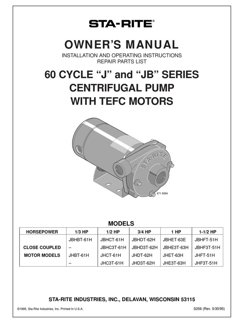
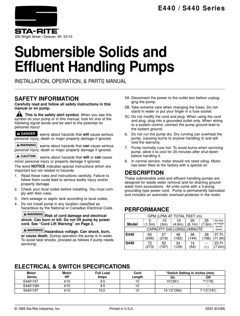
  9. STA-RITE 300EL Series User manual

STA-RITE 300EL Series User manual

Carefully read and follow all safety instructions in
this manual or on pump.
This is the safety alert symbol.
When you see this symbol on your pump or in this manual,
look for one of the following signal words and be alert to
the potential for personal injury.
warns about hazards that will cause serious
personal injury, death or major property damage if ignored.
warns about hazards that can cause serious
personal injury, death or major property damage if ignored.
warns about hazards that will or can cause
minor personal injury or property damage if ignored.
The word NOTICE indicates special instructions which are
important but not related to hazards.
1. Read these rules and instructions carefully. Failure to
follow them could lead to serious bodily injury and/or
property damage.
2. Check your local codes before installing. You must
comply with their rules.
3. Vent sewage or septic tank according to local codes.
4. Do not install pump in any location classified as
hazardous by National Electrical Code, ANSI/NFPA
70-1984.
Risk of electrical shock. Can burn
or kill. Do not lift pump by power cord. See “Cord Lift
Warning” on Page 3.
Hazardous voltage. Can shock,
burn, or cause death. During operation the pump is
in water. To avoid fatal shocks, proceed as follows if
pump needs servicing:
5A. Disconnect power to outlet box before pulling pump
cord plug.
5B. Take extreme care when changing fuses. Do not stand
in water or put your finger in fuse socket.
5C. Do not modify cord and plug. When using cord and
plug, plug into a grounded outlet only. When wiring to
a system control, connect pump ground lead to system
ground.
6. Do not run pump dry. Dry running can overheat pump,
(causing burns to anyone handling it) and will void war-
ranty.
7. Pump normally runs hot. To avoid burns when servic-
ing pump, allow it to cool for 20 minutes after shut-
down before handling it.
8. In normal service, motor should not need oiling. Motor
has been filled at the factory with a special oil; when
overhauling, replace with new oil. Use only oil speci-
fied in parts list of this manual. Use of any other oil
could damage motor and will void warranty.
STA-RITE
OWNER'S MANUAL
Installation • Operation • Repair Parts
Submersible Solids Handling Pumps
300EL, 400EL, 400S Series
STA-RITE INDUSTRIES, INC., DELAVAN, WISCONSIN 53115
Printed in U.S.A. © 2003, Sta-Rite Industries, Inc. S311 (Rev. 5/19/03)
SAFETY INSTRUCTIONS
INSTALLATION
NOTICE: Install pump on a hard, level surface (cement,
asphalt, etc.). Never place pump directly on earth, clay or
gravel surfaces.
Piping
When installed in a sewage system, pipe must be capable of
handling semi-solids of at least 2" diameter.
When installed in an effluent system, pipe must be capable
of handling semi-solids of at least 3/4" diameter.
The rate of flow in the discharge pipe must keep any solids
present in suspension in the fluid. To meet minimum flow
requirements (2 feet per second in discharge line), size pipe
as follows:
A Pipe Size Of: Will Handle a Flow Rate Of:
1-1/2" 12 GPM
2" 21 GPM
2-1/2" 30 GPM
3" 48 GPM
In a sewage system use a 2" check valve in pump discharge
to prevent backflow of liquid into sump basin. The check
valve should be a free flow valve that will easily pass solids.
Be sure check valve installation complies with local codes.
In an effluent system use a 1-1/2" check valve in pump dis-
charge to prevent backflow of liquid into sump basin. The
check valve should be a free flow valve that will easily pass
solids. Be sure check valve installation complies with local
codes.
NOTICE: For best performance of check valve when han-
dling solids, do not install it with discharge more than 45°
above the horizontal. Do not install check valve in a vertical
position as solids may settle in valve and prevent opening
on startup.
Drill a 3/16" hole in discharge pipe about 1–2" above pump
discharge connection (but below check valve) to prevent air-
locking the pump.
Electrical
Hazardous voltage. Can shock, burn,
or cause death. When installing, operating, or servicing
this pump, follow safety instructions listed below.
1. DO NOT splice the electrical power cord.
2. DO NOT allow electrical cord plug to be submerged.
3. DO NOT use extension cords. They are a fire hazard and
can reduce voltage sufficiently to prevent pumping
and/or damage motor.
4. DO NOT handle or service pump while it is connected to
power supply.
5. DO NOT remove grounding prong from plug or modify
plug.To protect against electrical shock, the power cord
is a three-wire conductor and includes a 3-prong ground-
ed plug. Plug pump into a 3-wire, grounded, grounding-
type receptacle. Connect pump according to NEC and
local codes.
For automatic operation, plug or wire pump into an auto-
matic float switch or pump controller. Pump will run contin-
uously when plugged directly into an electrical outlet.
Connect or wire pump to its own circuit with no other out-
lets or equipment in the circuit. Size fuses or circuit break-
ers according to chart below.
Risk of electrical shock and fire. Be
sure that power supply information (Voltage/
Hertz/Phase) on pump motor nameplate matches
incoming power supply exactly. Install pump
according to all electrical codes that apply.
Fuse or Circuit Dual Element Time
HP Voltage Breaker Amps Delay Fuse Amps
PWEL3B01A
1/3 115 15 10
PWEL4C01
4/10 115 15 10
PWEL4C01A
4/10 115 15 10
PWS4C01A-01
4/10 115 15 10
Operation and Installation
NOTICE: Do not allow pump to run in a dry sump. It will
void the warranty and may damage the pump.
An automatic overload protector in the motor will protect
motor from burning out due to overheating/overloading.
When motor cools down, overload protector will automati-
cally reset and start motor.
If overload trips frequently, check for cause. It could be a
stuck impeller, wrong/low voltage, or electrical failure in
motor. If an electrical failure in the motor is suspected,
replace pump.
Pump is permanently lubricated. No oiling or greasing is
required.
SERVICE
General
Hazardous voltage. Can shock, burn,
or cause death. Before removing pump from basin for
service, always disconnect electrical power to pump and
control switch.
Risk of electrical shock. Can burn or
kill. Do not lift pump by power cord. See “Cord Lift
Warning” on Page 3.
Submerge complete pump in a disinfectant solution (chlorox
or chlorine) for at least one hour before disassembling
pump.
Impeller Replacement
1. Unplug cord from power source.
2. Remove screws from lower volute housing (Key #1) and
separate volute halves.
3. Hold shaft with screwdriver in slot in end of shaft;
unscrew impeller (Key #2) counter clockwise from shaft.
4. Thread new impeller onto shaft. Hold shaft with screw-
driver and tighten impeller firmly hand tight.
5. Remount lower volute housing (Key #1).
6. Plug in unit.
7. Pump is ready for operation. To avoid flooding, test
pump before operating by filling sump and running pump
through one complete cycle to be sure that switch works.
2
3
IF MOTOR FAILS, REPLACE PUMP.
3
2
1
5
Motor
4
1066 0595
1. Attempting to lift or support pump by
power cord can damage cord and cord
connections.
2. Cord may pull apart, exposing bare wires
with possibility of fire or electrical
shock.
3. Lifting or supporting pump by power
cord will void warranty.
4. Use lifting ring or handle on top of pump
for all lifting/lowering of pump.
Disconnect power to pump before doing
any work on pump or attempting to
remove pump from sump
1476 0195
Risk of electrical shock.
Can burn or kill.
Do not lift pump by
power cord.
WARNING
Key Part PWEL3B01A PWEL4C01 PWEL4C01A PWS4C01A-01
No. Description Qty. 115 Volt 115 Volt 115 Volt 115 Volt
1Lower Volute 1 PW1-12P PW1-12P PW1-12P PW1-11P
2Impeller 1 PW5-13P PW5-14P PW5-14P PW5-15P
3Upper Volute 1 PW1-10P PW1-10P PW1-10P PW1-10P
4Power Cord 1 PS17-59 PS17-59 PS17-59 PS17-59
5Automatic Float Switch* 1 PS117-146P – PS117-146P PS117-146P
REPAIR PARTS LIST
* Models with “A” suffix only.
Sudden Starts. If power is on to pump
when thermal overload resets, pump may start
without warning. If you are working on pump, you
may get an electrical shock or impeller may catch
fingers or tools. Disconnect power before servicing
pump.
4
A. Pump fails to operate: 1. Check to be sure that power cord is securely plugged into outlet or securely wired
into controller or switch box. Disconnect power to outlet before handling pump
or motor.
2. Check to be sure you have electrical power.
3. Check that liquid fluid level is high enough to activate switch or controller.
4. Check to be sure that there is a 3/16" vent hole in discharge pipe and it is not
plugged.
5. Check for blockage in pump inlet, impeller, check valve or discharge pipe.
6. Thermal overload may have tripped. Test start pump; if it starts and then stops
immediately, disconnect from power source for 30 minutes to allow motor to cool,
then reconnect to power source. Check for cause of overheating/overloading.
B. Pump fails to empty sump: 1. Be sure all valves in discharge valve are fully open.
2. Clean out discharge pipe and check valve.
3. Check for blockage in pump inlet or impeller.
4. Pump not sized properly. A higher capacity pump may be required.
C. Pump will not shut off: 1. Check switch or controller automatic floats for proper operation and location.
See installation instructions for switch/controller.
2. If pump is completely inoperative or continues to malfunction, consult your
local serviceman.
TROUBLES-REMEDIES
LIMITED WARRANTY
Sta-Rite warrants to the original consumer of the products listed below, that they will be free from defects in material and work-
manship for the Warranty Period from the date of installation as noted.
Product Warranty Period
Water Systems Products – jet pumps, 1 year
small centrifugal pumps, submersible pumps
and related accessories
Con-Aire®tanks 5 years
Sump/Sewage/Effluent Products 1 year
Our warranty will not apply to any product that has been subject to negligence, misapplication, improper installation or mainte-
nance. In the event a three phase submersible motor is operated with single phase power through a phase converter, or if three-leg
ambient compensated, extra-quick trip overload relays of recommended size are not used, our warranty is void.
Buyer’s only remedy and Sta-Rite’s only duty is to repair or replace defective products (at Sta-Rite’s choice). Buyer agrees to pay
all labor and shipping charges associated with this warranty and to request warranty service through the installing dealer as soon
as a problem is discovered. If warranty service is requested more than 30 days after the Warranty Period has ended, it will not be
honored.
STA-RITE SHALL NOT BE LIABLE FOR ANY CONSEQUENTIAL, INCIDENTAL, OR CONTINGENT DAMAGES
WHATSOEVER.
THE FOREGOING WARRANTIES ARE EXCLUSIVE AND IN LIEU OF ALL OTHER EXPRESS WARRANTIES.
IMPLIED WARRANTIES, INCLUDING BUT NOT LIMITED TO THE IMPLIED WARRANTIES OF MERCHANTABILITY
AND FITNESS FOR A PARTICULAR PURPOSE, SHALL NOT EXTEND BEYOND THE WARRANTY PERIOD PROVID-
ED HEREIN.
Certain states do not permit the exclusion or limitation of incidental or consequential damages or the placing of limitations on the
duration of an implied warranty, therefore, the limitations or exclusions herein may not apply. This warranty sets forth specific
legal rights and obligations, however, additional rights may exist, which may vary from state to state.
Supersedes all previous publications
Sta-Rite Industries, Inc. 293 Wright St., Delavan, WI 53115

This manual suits for next models

2

Other STA-RITE Water Pump manuals

STA-RITE 5P6R Series User manual

STA-RITE

STA-RITE 5P6R Series User manual

STA-RITE SuperMax S5P1R User manual

STA-RITE

STA-RITE SuperMax S5P1R User manual

STA-RITE SP550120T Guide

STA-RITE

STA-RITE SP550120T Guide

STA-RITE HN series User manual

STA-RITE

STA-RITE HN series User manual

STA-RITE Signature 2000 User manual

STA-RITE

STA-RITE Signature 2000 User manual

STA-RITE Dura-Jet User manual

STA-RITE

STA-RITE Dura-Jet User manual

STA-RITE MAX-E-PRO Series P6RA User manual

STA-RITE

STA-RITE MAX-E-PRO Series P6RA User manual

STA-RITE MAX-E-GLAS II P4E6D-150L User manual

STA-RITE

STA-RITE MAX-E-GLAS II P4E6D-150L User manual

STA-RITE DURA-JET JSAYDL User manual

STA-RITE

STA-RITE DURA-JET JSAYDL User manual

STA-RITE MAX-E-GLAS IITM User manual

STA-RITE

STA-RITE MAX-E-GLAS IITM User manual

STA-RITE DP233110V User manual

STA-RITE

STA-RITE DP233110V User manual

STA-RITE JHSC-61USF User manual

STA-RITE

STA-RITE JHSC-61USF User manual

STA-RITE DURA-JET JSACL User manual

STA-RITE

STA-RITE DURA-JET JSACL User manual

STA-RITE DURA-GLAS II P4RA Series User manual

STA-RITE

STA-RITE DURA-GLAS II P4RA Series User manual

STA-RITE AR204-L 3/4 HP User manual

STA-RITE

STA-RITE AR204-L 3/4 HP User manual

STA-RITE DURA-JET 5JSAC-A User manual

STA-RITE

STA-RITE DURA-JET 5JSAC-A User manual

STA-RITE E440 Series Guide

STA-RITE

STA-RITE E440 Series Guide

STA-RITE DYNA-WAVE MPRA Series User manual

STA-RITE

STA-RITE DYNA-WAVE MPRA Series User manual

STA-RITE AN Series User manual

STA-RITE

STA-RITE AN Series User manual

STA-RITE HMS-1FL Series User manual

STA-RITE

STA-RITE HMS-1FL Series User manual

STA-RITE HC-01 User manual

STA-RITE

STA-RITE HC-01 User manual

STA-RITE 400S Series User manual

STA-RITE

STA-RITE 400S Series User manual

STA-RITE ALB User manual

STA-RITE

STA-RITE ALB User manual

STA-RITE J Series User manual

STA-RITE

STA-RITE J Series User manual

Popular Water Pump manuals by other brands

Xylem Flojet 02830000A INSTALLATION & SERVICE INFORMATION

Xylem

Xylem Flojet 02830000A INSTALLATION & SERVICE INFORMATION

Conel FLOW TP12-A Installation and operation instructions

Conel

Conel FLOW TP12-A Installation and operation instructions

ARO ARO 666250-XXX-C Operator's manual

ARO

ARO ARO 666250-XXX-C Operator's manual

evenes EV-ZUP 15 Series manual

evenes

evenes EV-ZUP 15 Series manual

Pentair HYDROMATIC HTS33M1 Installation, Operation & Parts Manual

Pentair

Pentair HYDROMATIC HTS33M1 Installation, Operation & Parts Manual

Flotec AT250701 owner's manual

Flotec

Flotec AT250701 owner's manual

Grundfos BMS Series Installation and operating instructions

Grundfos

Grundfos BMS Series Installation and operating instructions

EINHELL 41.709.64 Original operating instructions

EINHELL

EINHELL 41.709.64 Original operating instructions

ARO ARO 662605 Operator's manual

ARO

ARO ARO 662605 Operator's manual

GORMAN-RUPP PUMPS 80 Series Installation, operation and maintenance manual

GORMAN-RUPP PUMPS

GORMAN-RUPP PUMPS 80 Series Installation, operation and maintenance manual

Blue Angel Pumps F50CIS Operating instructions and parts manual

Blue Angel Pumps

Blue Angel Pumps F50CIS Operating instructions and parts manual

Tecnosystemi smart clima 12170027 Manual for installation

Tecnosystemi

Tecnosystemi smart clima 12170027 Manual for installation

INOXPA TLS Series Installation, service and maintenance instructions

INOXPA

INOXPA TLS Series Installation, service and maintenance instructions

Pentair Jung Pumpen PLANCOFIX LINE instruction manual

Pentair Jung Pumpen

Pentair Jung Pumpen PLANCOFIX LINE instruction manual

Magnum MSD 1021 Operating & parts manual

Magnum

Magnum MSD 1021 Operating & parts manual

Knauer BlueShadow 80P instructions

Knauer

Knauer BlueShadow 80P instructions

Unibloc-Pump LABTOP 200 Series Operation and service manual

Unibloc-Pump

Unibloc-Pump LABTOP 200 Series Operation and service manual

BBC P230/06 instruction manual

BBC

BBC P230/06 instruction manual

manuals.online logo
manuals.online logoBrands
  • About & Mission
  • Contact us
  • Privacy Policy
  • Terms and Conditions

Copyright 2025 Manuals.Online. All Rights Reserved.