manuals.online logo
Brands
  1. Home
  2. •
  3. Brands
  4. •
  5. STA-RITE
  6. •
  7. Water Pump
  8. •
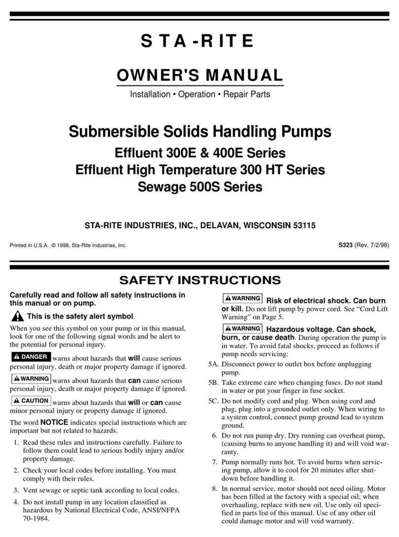
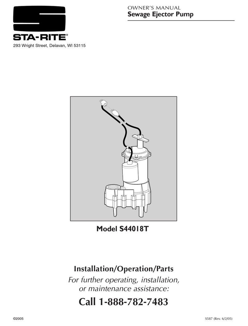
  9. STA-RITE 700S Series User manual

STA-RITE 700S Series User manual

Carefully read and follow all safety instructions in
this manual or on pump.
This is the safety alert symbol. When you see this
symbol on your pump or in this manual, look for one of
the following signal words and be alert to the potential for per-
sonal injury.
warns about hazards that will cause serious per-
sonal injury, death or major property damage if ignored.
warns about hazards that can cause serious per-
sonal injury, death or major property damage if ignored.
warns about hazards that will or can cause
minor personal injury or property damage if ignored.
The word NOTICE indicates special instructions which are
important but not related to hazards.
1. To avoid serious injury and/or property damage, read these
rules and instructions carefully.
2. Check your local codes before installing. You must comply
with their rules.
3. Vent sewage or septic tank according to local codes.
4. Pump normally runs hot. To avoid burns when servicing
pump, allow it to cool for 20 minutes after shut-down
before handling it.
5. Do not run pump dry. Dry running can overheat pump and
will void warranty.
6. Pump is permanently lubricated. No oiling or greasing is
required in normal operation. For overhaul, see instructions
under "Service".
Hazardous voltage. Can shock, burn, or
cause death. During operation the pump is in water. To avoid
fatal shocks, proceed as follows if pump needs servicing:
7A. Ground pump according to all applicable codes and ordi-
nances.
7B. Disconnect power to outlet box or circuit breakers before
servicing
7C. To reduce risk of electric shock, take care when changing
fuses or resetting circuit breakers. Do not stand in water
when working on control box or with circuit breakers.
Single Phase Pumps:
7D. Do not modify cord and plug unless removing plug com-
pletely and wiring pump directly into switch box or con-
troller. When using cord and plug, plug into a grounded
outlet only. When wiring to a system control, connect
pump ground lead to system ground.
Three Phase Pumps:
7E. Three phase pumps are intended for permanent connection
only. Provide strain relief at control box for power supply
cord connection to box.
INSTALLATION
NOTICE: Install pump on a hard, level surface (cement,
asphalt, etc.). Never place pump directly on earth, clay or gravel
surfaces. Basin must be at least 458 mm (18") in diameter and
762 mm (30") deep.
OWNER'S MANUAL
Installation • Operation • Repair Parts
Submersible Sewage/Solids Handling Pumps
700S Series, 50 Hz, Single and Three Phase
Printed in U.S.A. © 2003 SX265 (3/20/03)
SAFETY INSTRUCTIONS
Piping
Piping must not be smaller than pump discharge.
When installed in a sewage system, pipe must be capable of
handling semi-solids of at least 51 mm (2") diameter.
The rate of flow in the discharge pipe must keep any solids pre-
sent in suspension in the fluid. To meet minimum flow require-
ments of 61 cm/sec (2 feet per second) in discharge line, size
pipe as follows:
A Pipe Size Of: Will Handle a Flow Rate Of:
51 mm (2”) 79.5 L/M (21 GPM)
63.5 mm (2-1/2”) 113.5 L/M (30 GPM)
76 mm (3”) 182 L/M (48 GPM)
Use a 51 mm (2") check valve in pump discharge to prevent
backflow of liquid into sump basin. The check valve should be a
free flow valve that will easily pass solids.
NOTICE: For best performance of check valve when handling
solids, do not install it with discharge more than 45° above the
horizontal. Do not install check valve in a vertical position as
solids may settle in valve and prevent opening on startup.
Drill a 5 mm (3/16") hole in discharge pipe about 25-50 mm
(1–2") above pump discharge connection (but below check
valve) to prevent airlocking the pump.
Electrical
Hazardous voltage. Can shock, burn, or
cause death. When installing, operating, or servicing this
pump, follow safety instructions below.
1. DO NOT splice the power cord, submerge electrical cord
plug, or use extension cords.
2. DO NOT handle or service pump while it is connected to
power supply.
3. DO NOT remove grounding prong from plug or modify
plug. Power cord on 1-phase units is a 3-wire conductor with
a 3-prong grounded plug. Plug pump into a 3-wire, ground-
ed, grounding-type receptacle. If there is no 3-wire grounded
receptacle to plug into, remove plug completely and wire
pump directly into terminal block in automatic float or
duplex controller box. Connect pump according to all applic-
able codes.
For automatic operation, plug or wire pump into an automatic
float switch or duplex controller. For continuous operation, plug
directly into an electrical outlet or wire directly into switch box.
Connect pump to its own circuit with nothing else on the cir-
cuit. See chart below for fuse or circuit breaker sizes.
Risk of electrical shock and fire. Be sure
that power supply information (Voltage/Hertz/Phase)
on pump motor nameplate matches incoming power
supply exactly. Install pump according to all electrical
codes that apply.
Dual Element
Voltage/ Time Delay
H.P. Phase Fuse Amps*
1/2 220/1 10
3/4 220/1 10
3/4 115/1 15
3/4 230/1 10
* Use time delay fuses or CBs in motor circuit. Do not use standard
fuses or CBs.
Operation and Installation
NOTICE: Do not allow pump to run in a dry sump. It will void
the warranty and may damage the pump.
An automatic overload protector in the motor will protect motor
from burning out due to overheating/overloading. When motor
cools down, protector will automatically reset and start motor.
If overload trips frequently, check for cause. It could be a stuck
impeller, wrong/low voltage, or electrical failure in motor. If an
electrical failure in the motor is suspected, have it serviced by a
competent repairman.
Pump is permanently lubricated. No oiling or greasing is
required in normal service.
SERVICE
General
Hazardous voltage. Can shock, burn, or
cause death. Before servicing pump, disconnect electrical
power to pump and control switch.
After removing basin cover and necessary discharge piping, lift
pump out of basin.
Place pump in an area where it can be cleaned thoroughly.
Remove all scale and deposits on pump.
Submerge pump in disinfectant (chlorox or chlorine) for at least
one hour before disassembling pump.
The pump motor housing contains a special lubricating oil.
Keep oil clean and free of water at all times.
NOTICE: Whenever motor housing is being removed for ser-
vice, remove oil and replace with new oil at reassembly. Use
only oil listed in parts list (Part No. U197-8A). When filling
with new oil, DO NOT overfill. To allow room for expansion,
oil level with cold motor should be about 6 mm (1/4") above top
of motor assembly.
Impeller, Seal, and Capacitor Replacement
Risk of electrical shock. Disconnect elec-
trical power from pump before doing any service work
on it!
Numbers refer to assembly drawing, Page 3.
Disassembly
1. Remove motor assembly from volute and set it on its side in
a clean area.
2. Hold impeller (Key No. 10); remove impeller nut and wash-
ers (Key Nos. 11 and 12).
3. Unscrew impeller (turn counter-clockwise) for cleaning.
4. Remove oil fill plug (Key No. 2). Turn pump upside down
to drain oil.
Risk of electric shock. Before touching
capacitor, discharge it by shorting the terminals
together with an amber handled screwdriver.
5. Loosen cord nut and grommet (Key Nos. 20 and 19) to allow
cord to slide. Remove 4 socket head cap screws (Key No.
17) from seal plate and remove motor cover (Key No. 5).
6. If replacing capacitor, remove wires from capacitor (Key
No. 3A). Remove capacitor.
7. Remove rotating half of seal off of shaft.
8. Cradle motor assembly so that it stands vertically with
motor shaft extending out of the bottom.
2
9. Remove through bolts from motor assembly. Remove
motor and shaft from seal plate.
10. With screwdriver, gently tap seat ring out of seal plate;
thoroughly clean seat cavity.
Re-assembly
NOTICE: Make sure that seal faces are clean and undamaged.
Apply Permatex #2 or equivalent sparingly to outside edge of
seal body.
1. Press new seal body into cavity in seal plate.
2. Reverse steps 7 through 9 (Page 2) to reassemble motor and
shaft.
NOTICE: Do not overtighten through bolts!
3. Slide new rotating member of seal onto shaft.
NOTICE: Coat rubber bellows with soap or oil to aid in
installing seal on shaft.
NOTICE: Do not nick or scratch carbon seal face when
passing it over shaft shoulder. Seal faces must be clean and
undamaged or seal may leak.
4. Reassemble impeller, washer, and impeller nut.
5. Install new capacitor. See picture below for electrical con-
nections to capacitor.
6. Inspect O-Ring gasket; replace if damaged. If it is not
nicked or scratched, clean and reinstall.
7. Reinstall motor cover, adjust power cord in connector and
retighten connector.
8. Fill motor with clean dielectric oil (Part No. U197-8A). To
allow room for expansion, oil level with cold motor should
be about 6 mm (1/4") above top of motor assembly.
3
1
2
3A
4
5
6
7
9A
9B
10
11
12
16
15
3B
17
18
8
14
19
20
13
Key No.4 Key No. 10 Key No. 21
Model H.P. Volts/Hz/ø Insulator Motor Ass’y Power Cord
5PWS7C07 1/2 220/50/1 PW218-114 PW5-3 PW117-232A-TSE
5PWS7D07 3/4 220/50/1 PW218-114 PW5-4 PW117-232A-TSE
5PWS7D08 3/4 220/50/3 PW218-119 PW5-4 PW117-235-TSE
5PWS7D09 3/4 380/50/3 PW218-119 PW5-4 PW117-235-TSE
Key Part
No. Description Qty Part No.
1Rope Handle Ring 1 U97-102SS
21/4” NPT Pipe Plug 1 U78-57DV
3A Capacitor (1 Phase only) 1 U18-1386
3B Capacitor Insulator (1 Phase only) 1 P18-1006
4Motor Assembly 4 See Chart Below
•Motor Through Bolts 4 U30-941
5Motor cover 1 PW18-54
61/4-20x1-1/2” Hex Hd Scr 4 U30-883SS
7Seal Plate 1 PW18-53
8Volute 1 PW1-3A
9Shaft Seal (Incl. 9A Bellows 1 U109-321SS
and 9B Mating Ring)
9A Seal Bellows 1
9B Seal Mating Ring 1
10 Impeller 1 See Chart Below
11 Hex Jam Nut 7/16-20 1 U36-33SS
12 Spring Washer 1 U43-112SS
13 O-Ring 1 U9-365
14 Discharge Flange Gasket 1 PW20-2
15 Discharge Flange 1 PW16-2W
16 5/16-18x1-1/2" Capscrew 2 U30-65SS
17 1/4-20x5/8" Soc Hd Screw 4 U30-109SS
18 Grommet 1 PW21-2
19 Power Cord Nut 1 PS18-83SS
20 Power Cord 1 See Chart Below
REPAIR PARTS
• Not Illustrated
Stator
Leads From
White
Red
Black
White
Green
Black
Capacitor
Cord Stator
Lead Leads
#L1 to #1 & 6
#L2 to #2 & 4
#L3 to #3 & 5
380 Volt
Cord Leads Stator Leads
#L1(Red) to #1
#L2(Black) to #2
#L3(White) to #3
Connect #4, 5, and 6
together.
Capacitor Connections
(Single Phase Only)
3-Phase Connections
208-230VStar (Wye)
Sudden Starts. If power is on to pump
when thermal overload resets, pump may start with-
out warning. If you are working on pump, you
may get an electrical shock or impeller may catch fin-
gers or tools. Disconnect power before servicing pump.
A. Pump fails to operate: 1. Check to be sure that power cord is securely plugged into outlet or securely wired
into controller or switch box. Disconnect power to outlet before handling pump
or motor.
2. Check to be sure you have electrical power.
3. Check that liquid fluid level is high enough to activate switch or controller.
4. Check to be sure that 5 mm (3/16") vent hole in discharge pipe is not plugged.
5. Check for blockage in pump inlet, impeller, check valve or discharge pipe.
6. Thermal overload may have tripped. Test start pump; if it starts and then stops
immediately, disconnect from power source for 30 minutes to allow motor to cool,
then reconnect to power source. Check for cause of overheating/overloading.
B. Pump fails to empty sump: 1. Be sure all valves in discharge valve are fully open.
2. Clean out discharge pipe and check valve.
3. Check for blockage in pump inlet or impeller.
4. Pump not sized properly. A higher capacity pump may be required.
C. Pump will not shut off: 1. Check switch or controller automatic floats for proper operation and location.
See installation instructions for switch/controller.
2. If pump is completely inoperative or continues to malfunction, consult your
local serviceman.
TROUBLES-REMEDIES

Other STA-RITE Water Pump manuals

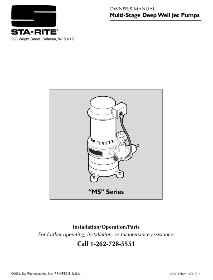
STA-RITE MPRA6D-146L Guide

STA-RITE

STA-RITE MPRA6D-146L Guide

STA-RITE SW Series Guide

STA-RITE

STA-RITE SW Series Guide

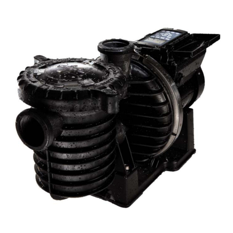
STA-RITE 5PRA Series User manual

STA-RITE

STA-RITE 5PRA Series User manual

STA-RITE MAX-E-PRO Series P6RA User manual

STA-RITE

STA-RITE MAX-E-PRO Series P6RA User manual

STA-RITE TPEA Series User manual

STA-RITE

STA-RITE TPEA Series User manual

STA-RITE Signature 2000 User manual

STA-RITE

STA-RITE Signature 2000 User manual

STA-RITE DPC User manual

STA-RITE

STA-RITE DPC User manual

STA-RITE BBN Series User manual

STA-RITE

STA-RITE BBN Series User manual

STA-RITE E440 Series Guide

STA-RITE

STA-RITE E440 Series Guide

STA-RITE SG12 Series Guide

STA-RITE

STA-RITE SG12 Series Guide

STA-RITE 300EL Series User manual

STA-RITE

STA-RITE 300EL Series User manual

STA-RITE C Series User manual

STA-RITE

STA-RITE C Series User manual

STA-RITE DURA-GLAS P2R Series Guide

STA-RITE

STA-RITE DURA-GLAS P2R Series Guide

STA-RITE INTELLIPRO 2 VST User manual

STA-RITE

STA-RITE INTELLIPRO 2 VST User manual

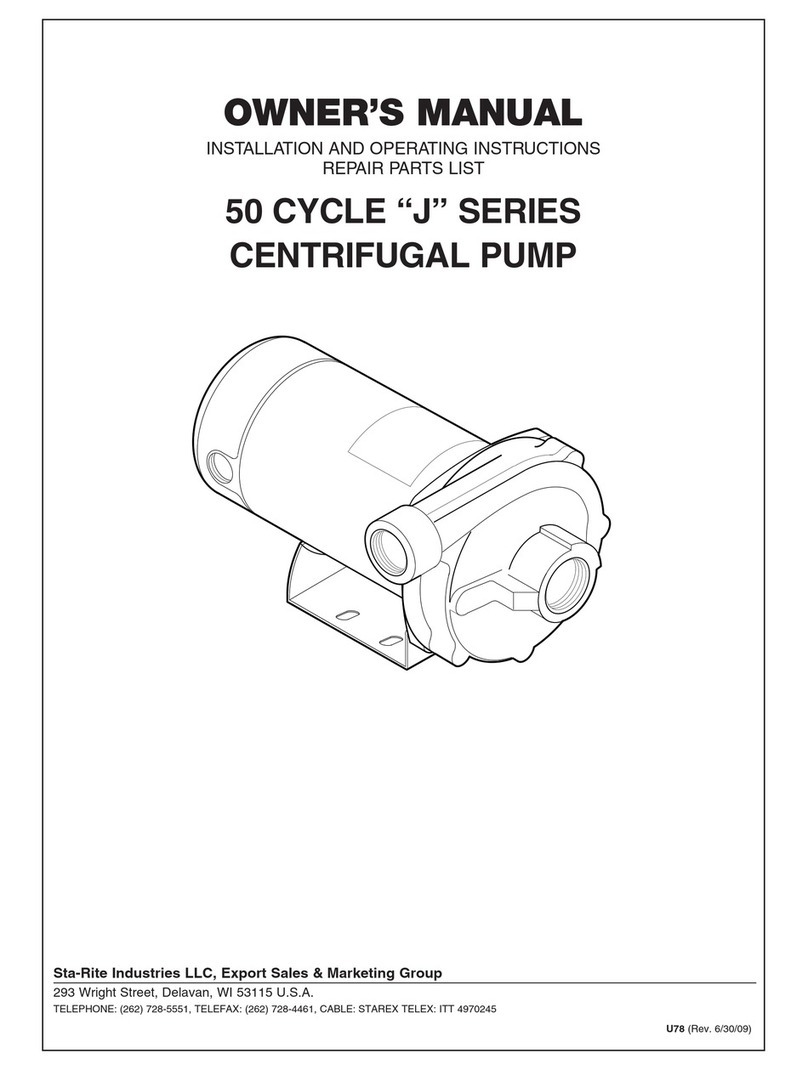
STA-RITE 700E Series User manual

STA-RITE

STA-RITE 700E Series User manual

STA-RITE SP550120T Guide

STA-RITE

STA-RITE SP550120T Guide

STA-RITE 400S Series User manual

STA-RITE

STA-RITE 400S Series User manual

STA-RITE Signature 2000 Series User manual

STA-RITE

STA-RITE Signature 2000 Series User manual

STA-RITE 10DOM05121 User manual

STA-RITE

STA-RITE 10DOM05121 User manual

STA-RITE ST33APP User manual

STA-RITE

STA-RITE ST33APP User manual

STA-RITE 300E Series User manual

STA-RITE

STA-RITE 300E Series User manual

STA-RITE PNB-1L User manual

STA-RITE

STA-RITE PNB-1L User manual

STA-RITE D Series User manual

STA-RITE

STA-RITE D Series User manual

STA-RITE HMS-1FL Series User manual

STA-RITE

STA-RITE HMS-1FL Series User manual

Popular Water Pump manuals by other brands

Tuthill GlobalGear Series Installation and service instructions

Tuthill

Tuthill GlobalGear Series Installation and service instructions

Thermal Care PT Series Operation, installation, and maintenance manual

Thermal Care

Thermal Care PT Series Operation, installation, and maintenance manual

Pentair Pool Products Hydromatic SKHS 100 Installation and service manual

Pentair Pool Products

Pentair Pool Products Hydromatic SKHS 100 Installation and service manual

Lochinvar ARMOR 151-200 Supplement sheet

Lochinvar

Lochinvar ARMOR 151-200 Supplement sheet

Graco President C Series Instructions-parts list

Graco

Graco President C Series Instructions-parts list

Sensidyne Gilian 5000 Operation manual

Sensidyne

Sensidyne Gilian 5000 Operation manual

Speck pumpen VZ 11 B Series operating instructions

Speck pumpen

Speck pumpen VZ 11 B Series operating instructions

Goulds GCEA V Series Installation and operating instructions

Goulds

Goulds GCEA V Series Installation and operating instructions

Core Separations SciMed CI Series manual

Core Separations

Core Separations SciMed CI Series manual

VERDER VERDERAIR VA 25 manual

VERDER

VERDER VERDERAIR VA 25 manual

Beckett CB20 quick start guide

Beckett

Beckett CB20 quick start guide

VERDER VERDERAIR VA-E50 Operation

VERDER

VERDER VERDERAIR VA-E50 Operation

Flint & Walling PB0508S031 Operating instructions & parts manual

Flint & Walling

Flint & Walling PB0508S031 Operating instructions & parts manual

Ingersoll-Rand ARO 650239-X-B Operator's manual

Ingersoll-Rand

Ingersoll-Rand ARO 650239-X-B Operator's manual

Pentair MBSP-3 Installation and operation manual

Pentair

Pentair MBSP-3 Installation and operation manual

Veeder-Root Maxxum Big-Flo 6 Installation, Operation And Service

Veeder-Root

Veeder-Root Maxxum Big-Flo 6 Installation, Operation And Service

Homa TP 53 Original instruction manual

Homa

Homa TP 53 Original instruction manual

Pressure Tech THE LW-351 Series Operating and service manual

Pressure Tech

Pressure Tech THE LW-351 Series Operating and service manual

manuals.online logo
manuals.online logoBrands
  • About & Mission
  • Contact us
  • Privacy Policy
  • Terms and Conditions

Copyright 2025 Manuals.Online. All Rights Reserved.