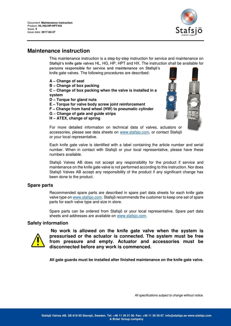
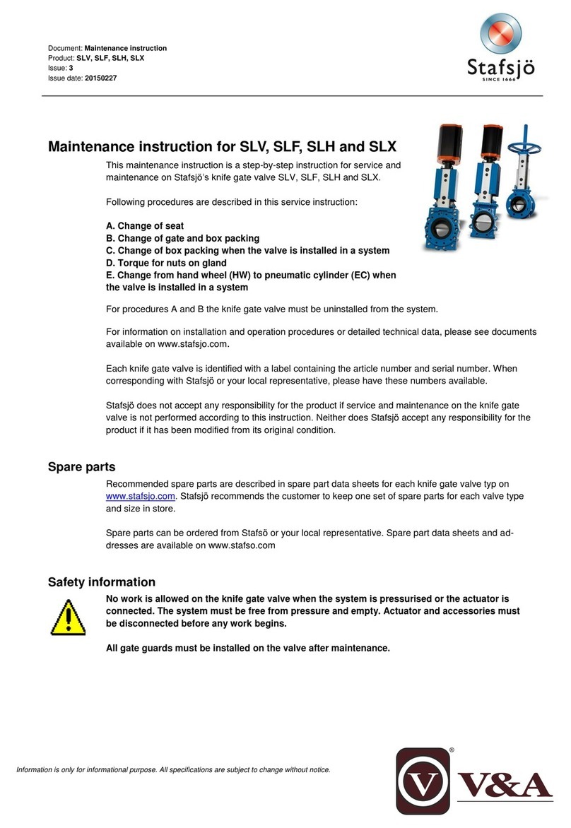
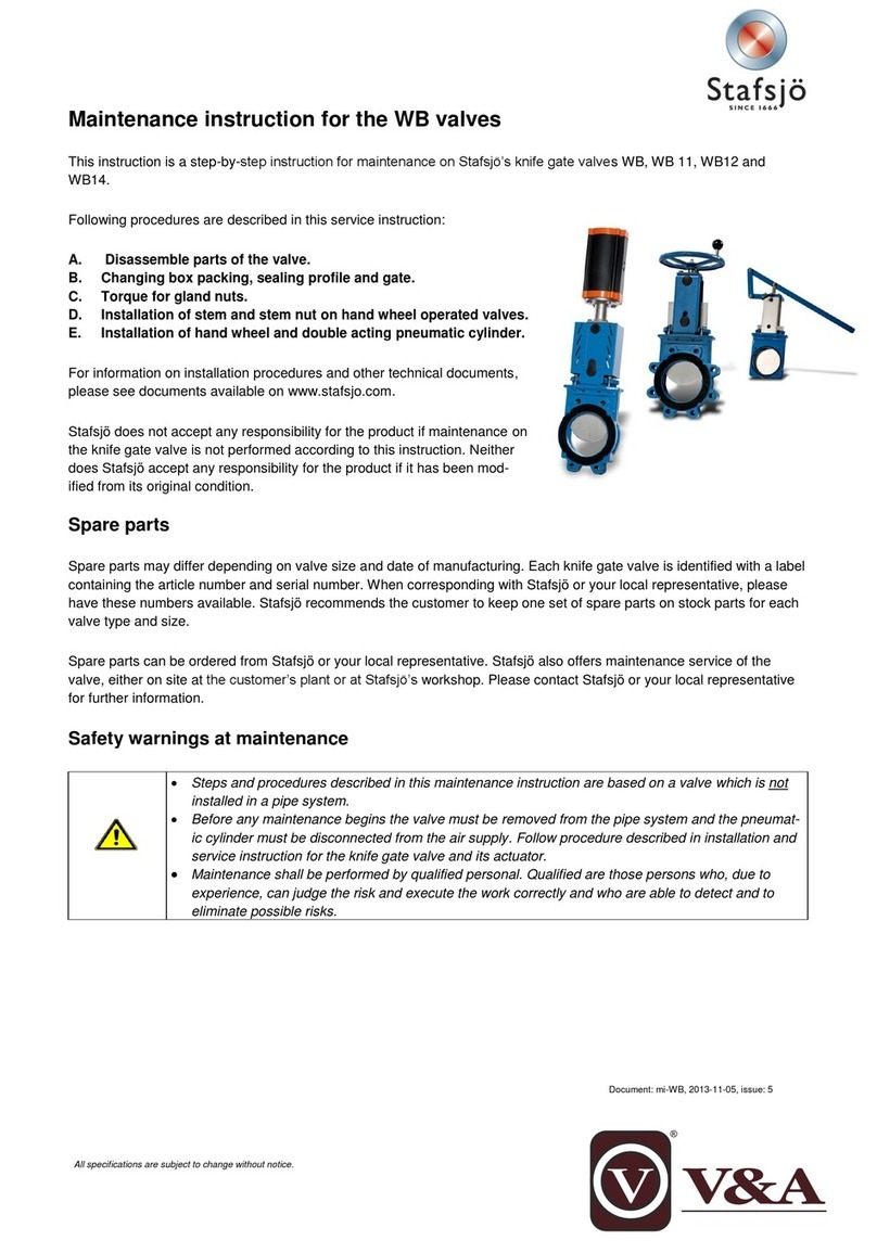
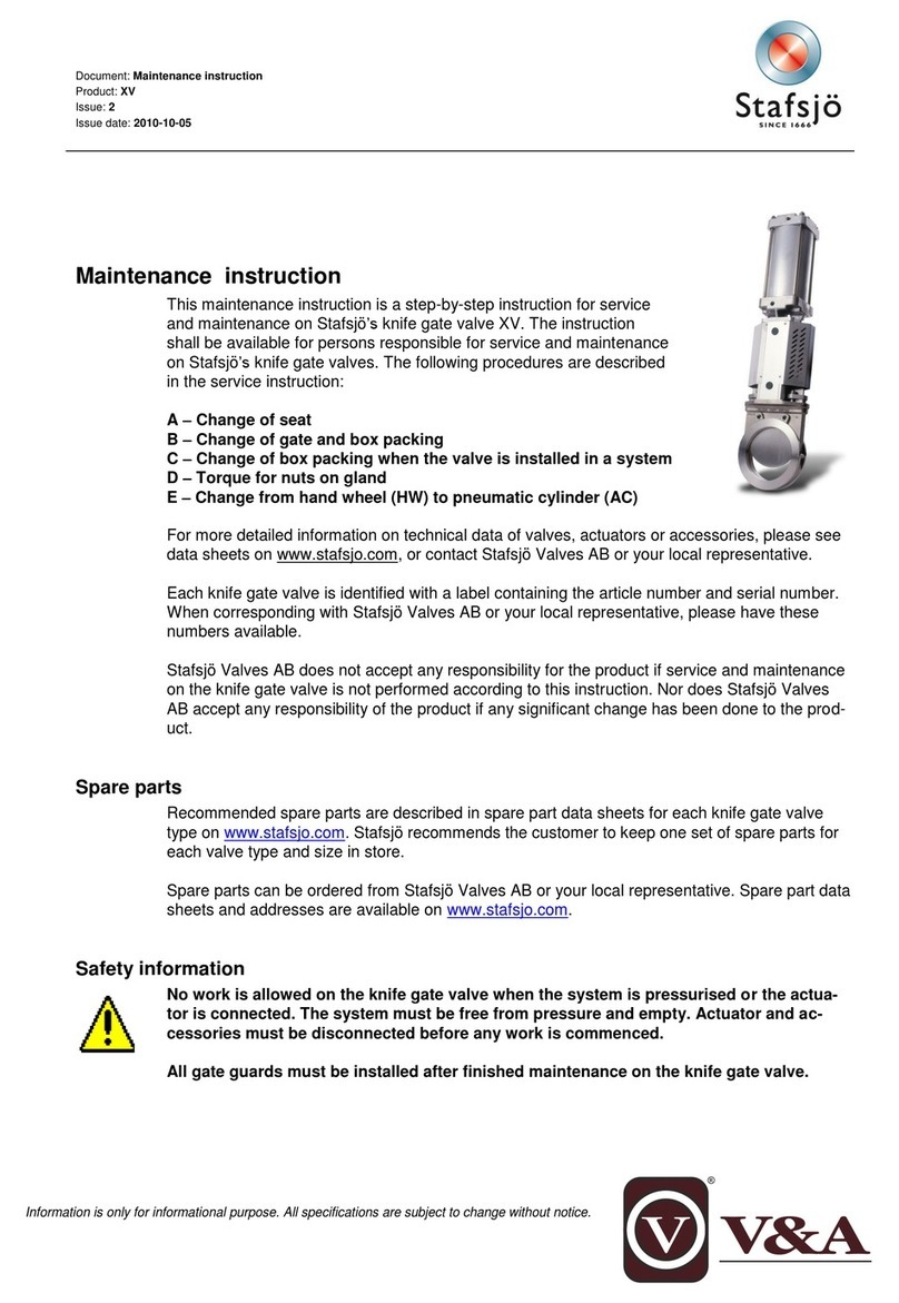
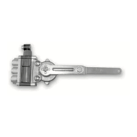
Stafsjö D2G Manual


Español
Deutsch
English
Français
Italiano
Nederlands
Norsk
Portoguês
Română
Content
Original
Installaon and service instrucon
Knife gate valves
Einbau- und Betriebsanleitung
Stoschieber
Instrucciones de instalación y servicio
Válvulas de guillona
Instrucons de montage et d’entreen
Vannes à guillone
Istruzioni per l’installazione e l’uso
Di valvole a ghigliona
Installae- en onderhoudshandleiding
Meskantafsluiters
Installasjons- og serviceinstruksjon
Skyvespjeldvenler, knivtype
Instruções de instalação e manutenção
Válvulas guilhona
Instrucțiuni de instalare și service
Vane cu sertar cuțit
Original
Installaons- och driinstrukon
Skjutspjällsvenler
Svenska

Document: is-VALVE, 23-07-03 issue: 17
Original
Installation and service instruction
Knife gate valves
Stafsjö Valves AB
SE-618 95 Stavsjö, Sweden
+46 11 39 31 00 | sales@stafsjo.se | www.stafsjo.com

Document: is-VALVE, 23-07-03 issue: 17
A) General
In this instruction a “knife gate valve” is shortly called “valve”.
A1 Symbols
In this instruction notes and warnings are marked with symbols:
XXXXX
Danger / Warning
Points out a dangerous situation which may cause personal injuries or death.
Advice
Has to be respected.
Information
Information useful to follow.
If these notes and warnings are not respected by the user, dangerous situations may occur and may invalidate the
warranty of the manufacturer.
A2 Valve destination
Valve types D2G, HG, HL, HP, HX, JTV, MV, RKO, RKS, SLF, SLV, SLH, SLX, TV, XV and WB are destined – after
installation between flange(s) in a pipe system – to shut off, to open or to control the flow within the admissible
pressure/temperature limits, defined in data sheet on www.stafsjo.com.
The flow shall be without vibrations and/or pressure chocks. The surrounding environment should not imply any risk
to the valve. This also implies to explosive environment – except for valves classified for ATEX- area and marked
accordingly.
Installation of the knife gate valve is preferred with the actuator in an upward position – except for RKO, RKS, JTV and
D2G.
At valve operation respect:
•The manufacturers declaration to EC directives,
•This original installation and service instruction which is supplied together with the valve.
If the valves are placed in any type of media or application that the valve material configuration is not suitable for,
Stafsjö cannot be held responsible for problems and incidents that may arise.
Stafsjö Valves AB does not accept any responsibility if this “Valve destination” is not observed.
A3 Related documents
Further information on the valves is available on www.stafsjo.com.
ds+valve type (i.e. ds-MV) = Data sheet with technical information (dimensions, material specification etc.)
mi+valve type (i.e. mi-MV) = Instructions for maintenance on each valve type.
sp+valve type (i.e. sp-MV)=Specify spare parts for each valve type.
acc+type of accessory (i.e. acc-SV)= Accessory for different types of valves. I.e solenoid valve.
Stafsjo_valve_specifications = Specification of parts and valve combinations.

Document: is-VALVE, 23-07-03 issue: 17
A4 Valve marking
Each valve is labelled as follows:
Type
Identification
Remarks
Manufacturer
E.g. Stafsjö
See label and valve body.
Manufacturer address
E.g. Stafsjö Valves AB, SE-618 95 Stavsjö,
Sweden, www.stafsjo.com
See type label.
Conformity
E.g. CE 2529 (if applicable)
Conformity with Pressure Equipment
Directive 2014/68/EU and notified body.
See type label.
ATEX conformity
E.g. II 2/2G Ex h IIC T6…T5 Gb/Gb
II 2/2D Ex h IIIC T68 ˚C ...T100 ˚C
-20℃≤Ta ≤+60℃(if applicable)
Approved to be used in specified ATEX area.
See type label.
Ser.No (Serial number)
E.g. 400-00634372-110-002
Sales order type - Sales order number -
Order line - Sequence number. See type
label.
Type
E.g. MV
Knife gate valve type. See type label.
Size
E.g. DN 300/12”
See type label. DN on valve body.
Rating
E.g. Max 10 bar working ps
Max working pressure at 20 °C. See type
label and valve body.
Rating
E.g. Max 10 bar differential ps
Max differential pressure at 20 °C. See type
label.
Drilling
E.g. PN10 – EN 1092-1
Flange drilling standard. See type label.
Body
E.g. EN 1.4408
Valve body material
See type label and valve body.
Gate
E.g. EN 1.4404
Gate material. See type label.
Seat
E.g. EPDM
Valve seat material. See type label.
Year
E.g. 2022
Manufacturing year. See type label.
The type label should not be covered so that the installed valve remains identifiable.
Refer to the “Serial number” of the valve marking at any contact with Stafsjö.
A5 Transport, storage and handling
Note
Additional requirements may be found in the actuator instruction, if any.
Storage and transport:
The valves are delivered with gate in, for the valve type, correct position during storage to ensure its function and to
protect the polished surface of the gate. Store the valve in a clean and dry environment and protect it against dirt,
dust and other contamination. Do not expose the valve to direct sunlight. If the valve is stored outside, it shall be
wrapped tightly in a plastic foil or similar to protect it against moisture or any dirt contamination. It should also be
stored high enough without any risk to be covered in snow or enclosed by water.
The valve has been packed according to the terms of delivery. It is important to make a visual inspection
at arrival. If transport damage is detected, report to the transportation company.

Document: is-VALVE, 23-07-03 issue: 17
Handling:
Lifting and moving shall be carried out with soft straps. Place and
fasten the soft strap on the valve body as shown in fig.1, ensure that
the valve is properly balanced before lifting. Make shure that all
equipment is designed to hold the weight of the valve.
Never place lifting equipment:
•On the actuator, accessories or gate guards.
•
In the bore of the knife gate valve, since it causes damages to the seat and retainer ring.
Specifically note that threaded hole on top of pneumatic cylinder type, is only for
handling the cylinder itself. See figure 2.
B) Installation/functional check
This instruction includes safety recommendations for foreseeable risks at installation into a (pipe)
system. The user is responsible to complete this instruction with warning notes for system-specific
aspects. All requirements of the system shall be observed.
B1 Safety warnings at installation
•Installation shall be performed by qualified personal. Qualified are those persons who, due to
experience, can judge the risks and execute the work correctly and who are able to detect and
eliminate possible risks.
•After installation, the function of the valve shall be in accordance with the valve and the actuator (if
any) destinations, see section A2.
•At the end of the installation the gland bolting shall be tightened according to table in section B7.
•A valve without an actuator must not be installed into the (pipe) system.
•Some valve types can be installed as end valves. Contact Stafsjö for specific requirements and
information.
Danger
1. A valve with an actuator shall only be operated if:
•The valve is installed between flanges or between a flange and a protective device.
•The gate guards are installed on the beams on automatic operated valves.
2. If the knife gate valve is installed as an end valve in a pipeline, always install protective equipment
to prevent people getting to close to the valve and being exposed to the media transported in the
system when the valve opens.
3. Do not climb or stand on the valve and/ or actuator
People’s life and health is at stake if this is not observed. Any other action is the responsibility of the
user.
B2 Conditions for installation
Make sure:
•To install valves according “Valve destination”, see section A2. Observe valve marking, see section A4.
•That the pipe section is not exposed to vibrations or other mechanical stresses which could deform the valve body
and affect the valve’s tightness and/or ability to operate.
•That the valve environment does not imply any risk to the valve, the actuator or the accessories. This also implies
to explosive environment – except for valves classified for ATEX- area and marked accordingly.
•That flanges, pipeline and the valve are empty, free from solid and sharp particles.
Fig.1
OK
Fig.2

Document: is-VALVE, 23-07-03 issue: 17
•That the valve is installed between flange(s) (fixed or loose) to ensure that the valve is securely fixed and that the
flange keeps tight.
•That the knife gate valve is protected against radiant heat, if the valve is placed near a heat source whose
temperature exceed maximum allowable temperature for the valve or its actuator.
•The mating (=gasket contact) surface of the flange cover the retainer ring completely. Detailed information on
flange drilling, threads, length and number of bolts is available in data sheet on www.stafsjo.com.
•To follow those instructions which are supplied with an actuator (if any).
•The pipeline is free from pressure.
•Additional requirements may be found in the actuator instruction – specifically to adjust the correct OPEN and
CLOSED positions before the valve is installed.
B3 Pressure, flow direction, valve position and flushing
When the knife gate valve is open, P1=P2, the pipe line pressure may not exceed maximum
allowable working pressure body according to each valve. When the valve is closed, the
differential pressure ∆P, is the difference between P1 and P2 (∆P = ± (P1-P2).
The differential pressure ∆P may not exceed maximum allowable differential pressure
according to each valve. Maximum allowable differential pressure for closed valve is
available in data sheets.
•Valve types XV, HL, HG, HP, HX, WB, D2G, SLV, SLF, SLH and SLX are bi-directional and can therefore be installed
independent of the pressure ratio in any direction in the pipe line.
•Valid for MV only:
This valve type has different differential pressure ∆P capacities in the flow directions. The maximum ∆P capacity of
the valve is achieved when the SEAT SIDE is installed as the valve outlet (towards P2) provided that P1 > P2. When
the valve is closed, the pressure ratio shall be P1>P2. Some sizes of MV equipped with specific seats are capable to
handle certain differential pressure in reversed pressure direction. For further information, see data sheets on
www.stafsjo.com.
•Valid for JTV, RKO and RKS only: These valve types have different differential pressure ∆P capacities in the flow
direction. The maximum ∆P capacity of the valve is achieved when the seat side is installed as the valve inlet
(towards P1) provided that P1>P2. When the valve is closed, the pressure ratio shall be P1>P2.
•Valid for TV only:
This valve shall be installed with the seat side to the tank. The removable retainer ring shall be mounted towards
the tank which implies that changing of the seat can only be done when the tank is empty.
•All valve types, except for valves D2G, JTV, RKO and RKS are preferred to be installed in a horizontal pipe (system)
with the actuator in a vertical upright position.
Valid for D2G, RKO, JTV and RKS only:
These valve types are designed to be installed in a vertical pipe.
•Valves installed in inclined position are mainly affected by type of media, flow rate and sedimentation in the
process. To estimate the effect of such is the responsibility of the customer. Stafsjö will assist on request.
•A valve can be equipped with flushing to improve function depending on type. When so is the case, customer has
too secure that flushing port will not be clogged. Preferably by use of check valve mounted directly on valve port.
Stafsjö can assist on request.
B4 Necessary support for special cases
The dead weight of a valve in large dimension together with its actuator or a small valve with heavy actuator, may
cause tensions/deformations in the valve that could affect the valve’s function, specifically when it is installed at
inclined positions or in a vertical pipe. In these cases, the valve and/or actuator shall be supported to avoid functional
failure.
Valves that are exposed to vibrations or other mechanical stresses can be subject to forces that will affect valves
tightness and ability to operate. In these cases, the valves and actuators shall be supported to avoid function failure.
Support details are the responsibility of the customer. Stafsjö will assist on request.
Fig. 3
Seat side
RKO, RKS,
JTV, TV
Seat side
MV
P1
P2

Document: is-VALVE, 23-07-03 issue: 17
B5 Steps to install
On handwheel operated valves, when the handwheel is not assembled at delivery, follow the steps below to assemble
the handwheel to the valve.
Handwheel with non-rising
stem
Handwheel with rising-stem
1. Assemble the handwheel to
the valve. Check that there is
not any play between the
actuator, bearing and yoke. If
there is, eliminate the play by
rotating the stem 360 degrees
clockwise. Then fixate the
handwheel with a locking nut.
1. Make sure that the
safety pin is mounted in
order to lock the gate.
Loosen the nuts from
the tie rods and remove
the temporary yoke
plate.
2. Assemble the
handwheel unit to the tie
rods and fixate it with
washers and nuts. Attach
the gate clevis to the
gate and fixate with
clevis pin and split pins.
3. Remove the safety pin.
For safety reasons, the pin
shall not be removed until
the hand-wheel unit is
assembled and the gate
clevis is properly attached
to the gate.
When the handwheel is assembled, install the valve into the pipe (system).
When installing the valve, make sure that:
•The valve’s centre line is on the same centre line as the flanged pipes.
•Flange surfaces of the pipe and valve must be exactly parallel.
If the flanges and the valve are not centred, the valve may be damaged by erosion and a dirt pocket may occur which
can lead to clogging and corrosion of the valve.
•Valve type RKO and XV must be installed in closed position only.
•Valve type SLV, SLF, SLH and SLX must be installed in open position only!
•When the SLV and SLF valve body are closed by bottom cover and/or when SLH and SLX purge ports
are closed by plugs, flushing is recommended through the purge ports at service if it is not clean fluid.
1. Place the gaskets between the valve body and the flange. Check that the gasket is well centered and covers the
complete surface of the retainer ring.
Valve types WB, SLV, SLF, SLH and SLX only:
These valve types are equipped with integrated rubber flange gaskets – additional gaskets are not
necessary.
2. Lubricate the bolts. This allows correct pre-setting of the flange and makes it easier to dismantle the bolting later.
All Valve types: Flange bolts of right length are necessary:
•Too long bolts could deform the valve body and result in leakage in the flange.
•Too short bolts could deform the threaded holes in the valve body at installation.
Choose bolts with the correct thread and length according to the flange drilling information in the data
sheet.
Fig. 4 Assembling of handwheel
Fig. 5

Document: is-VALVE, 23-07-03 issue: 17
3. Tighten the bolts first manually and then evenly and crosswise, for a uniform load of the gasket, with a torque as
required by the gasket manufacturer. Valve type SLV, SLF, SLH and SLX shall be assembled with the mating
surfaces of the valve body and the pipe flanges up to metal/metal contact. See fig. 6.
Valid only for SLV, SLF DN 80-DN 450, SLH DN 80-DN 450 and SLX DN 80-DN 450
Make sure that the flange is centered and is covering the metal frame around the seat.
Tighten flange bolts crosswise to eliminate any gap between body and flange.
To ensure the seats will stay in correct position after every valve manoeuvring, we
recommend using load distribution rings (LDR) on the SLV, SLF, SLH and SLX valves
when:
•The pipelines are rubber lined and/or the flanges are partly or entirely rubber
covered.
•The inner diameter of the connecting pipes and/or flanges is larger than the
inlet diameter of the valve.
•The outside diameter of the raised flange is not large enough to cover the
metal frame around the seat in order to accomplish metal to metal contact
between the valve and flange.
If load distribution rings are ordered they are as standard assembled on the valve upon delivery.
4. To finish the installation, make an operational test by opening /closing the valve. Observe the actuator (if any)
instructions.
•A valve with handwheel should be operated with normal hand force. Exceptional force used to close the valve
can damage it.
•A valve with electric/pneumatic actuator shall be operated by the plant control signals into its end positions,
i.e. OPENED and CLOSED.
•At connection of an actuator to the plant control system the actuator instructions shall be followed.
5. If the pipeline is to be cleaned by flushing in order to wash out impurities, the valve must be opened 100 %.
Fig. 6
Fig. 7

Document: is-VALVE, 23-07-03 issue: 17
Valves with actuator supplied by Stafsjö are exactly adjusted in the end positions:
This adjustment shall not be changed as long as the valve operates correctly.
Only for Valves with electric actuator:
Ensure that the actuator motor stops by the signal of the limit switch for closed and open position of the
actuator. Exceptional force may damage the valve. The signal of the torque switch may be used for signal
for faulted conditions. For further information, see the actuator instruction.
B6 Installation in an ATEX-classified area
Note:
Additional requirements may be found in the actuator instruction, (if any).
This ATEX instruction is valid along other instructions in this document.
In ATEX-classified zones, in accordance with ATEX Directive 2014/34/EU, only valves with ATEX-
classification and the relevant valve marking shall be installed.
Additional requirements are to be find in Stafsjö’s ATEX installation instructions for respective category
Additional to the requirements above make sure that:
•The valve is part of the plants earthed system.
•The user has performed a risk analysis of the pipeline and valve in accordance with the guidelines of ATEX Directive
2014/34/EU.
B7 Pressure testing after installation (if necessary)
Each Valve has been pressure tested before delivery by the manufacturer. For pressure test of the pipe section with a
knife gate valve installed the conditions for the system apply but with the following restrictions:
•The pressure test shall not exceed 1,5 x max. working pressure of the valve body (see valve marking). The gate
shall be open.
•Pressure test with valve in closed position shall not be tested more than 1,1x max. differential pressure in
preferred pressure direction, (see datasheets) in order to prevent overload of the gate.
Immediately at this operation check the stuffing box tightness. In case of leakage:
Tighten the gland nuts evenly crosswise and bit by bit until leakage stop. Do not tighten more than
necessary!
Recommended maximum torque
DN
DN 50 – DN 80
DN 100 – DN 150
DN 200 – DN 300
> DN 350
Nm
20
25
30
35
Ibf x ft
15
18
22
26
For the valves HP, HX and other high-pressure versions, observe the additional instruction: “Installation
of high-pressure knife gate valves – tighten the gland or double gland”.

Document: is-VALVE, 23-07-03 issue: 17
B8 Disassembling the valve
Note:
Additional requirements may be found in the actuator (if any) instruction.
For the valve the same safety instructions apply as for the pipe (system) and for the control system to which the
actuator (if any) is connected. The respect of these requirements shall be followed.
Danger
Disassembling the valve from the pipe line may only be done when:
•the pipe section is free from pressure and is empty
•all the electronic and/or pneumatic/hydraulic connections have been disconnected
People’s life and health is at stake if this is not observed. Any other action is the responsibility of the
user.
Disassemble the valve in following steps:
1. Depressurise the pipe section and drain it completely.
2. Disconnect all electric and/or pneumatic/hydraulic connections.
3. Fasten and use soft straps if necessary (see also Fig.1 in section A5). Make sure not to damage the valve, gate,
gate guards or any accessory.
4. Take out the valve from the pipe carefully in order to protect the flange gaskets.
5. At transport and storage observe section A5.
C) Service and maintenance
Note
Additional requirements may be found in the actuator instruction.
The user shall make a risk analysis as per Machinery Directive 2006/42/EC for the pipe system. Stafsjö supplies the
following documents for it:
•The original installation and service instruction of the valve.
•An installation and service instruction of the actuator (if any)
•The Declaration of conformity) to EC Directives.
This instruction includes safety notes for industrial application for any foreseeable risk at use of the
valve. It is the responsibility of the user/planner to complete this instruction with warning notes for
plantspecific risks.
Further information on Stafsjö’s valves is available on www.stafsjo.com.

Document: is-VALVE, 23-07-03 issue: 17
C1 Safety warnings at service and maintenance
•At operation, the function of the valve shall be in compliance with the <Valve Destination>, see
section A2.
•The service conditions of the valve shall be in compliance with the valve markings, see section A4.
•Service and maintenance shall be performed by qualified personal. Qualified are those persons who,
due to experience, can judge the risk and execute the work correctly and who are able to detect and
to eliminate possible risks.
•At service the valve shall be inspected regularly for leakage or other effects that could affect the
safety for the personnel. The interval for these inspections depends on operating data, see C3
•If a fault or problem is detected at an inspection or manoeuvre test, the knife gate valve must be
maintained as soon as possible
•Valves, destined for use in an ATEX classified zone, must be marked according to the ATEX directive.
•At any start up, the stuffing box shall be visually inspected for leakage. If any leakage is detected, the
nuts on the gland shall be retightened according to table in section B7. Except for this action, no
maintenance is allowed on the valve when the pipe line is pressurised.
•At maintenance or repair of an actuator, it shall be disconnected as described in section B8. The pipe
section must be free from pressure and completely drained at both sides of the valve before any
maintenance begins.
•Some valve types can be installed as end valves. Contact Stafsjö for specific requirements and further
information.
•The temperature of the exterior parts of the valve depends of the fluid temperature inside – any
protective insulation is in the responsibility of the user.
•When the SLV and SLF valve body are closed by bottom cover and/or when SLH and SLX purge ports
are closed by plugs, flushing is recommended through the purge ports at service if it is not clean fluid.
Danger
1. The stuffing box packing together with the gland makes sure that no media reaches surrounding
environment where the gate exit the valve body. When the stuffing box packing (braids) shall be
changed, the gland bolts must be loosened, and the the pipe section shall be depressurised and
empty.
2. A valve with an actuator shall be actuated only if:
•The valve is installed between flanges or between a flange and a protective device.
•The gate guards are installed on the beams, on automatic operated valves.
3. If you install the knife gate valve as an end valve in a pipeline, always install protective equipment to
prevent people getting to close to the valve and being exposed to the media transported in the
system when the valve opens.
People’s life and health is at stake if this is not observed. Any other action is the responsibility of the user.
C2 Manual and automatic actuation
A knife gate valve with handwheel closes clockwise as standard. Exceptions may occur based on customer requests.
A valve with automatic actuator is operated following the signals from the plant control system. Valves equipped with
actuator supplied by Stafsjö are exactly adjusted to stop in the exact end positions. This adjustment shall not be
changed as long as the valve operates correctly.
Valves with infrequent operation:
Stafsjö recommends a full operation test (open and close) at least twice a year (six months frequency) at normal
operating conditions. For severe services and/or specific application more frequent test intervals may be needed. It is
at the user's responsibility to evaluate which interval is suitable for their application/ process.

Document: is-VALVE, 23-07-03 issue: 17
C3 Maintenance
Inspect the valves on regular basis for any leakages. Seat and box packing are wear parts that have to be replaced
regularly. The interval for both inspection and replacement depends on the application and operating data such as
pressure, temperature, erosion, chemical, mechanical effect of the media on the materials in the knife gate valve and
on how often the valve is operated.
If a leakage is detected in the stuffing box area, re-tighten the nuts on top of the gland according section B7. If the
leakage does not stop or if any other leakage is detected, the valve needs to go through maintenance.
Danger
Make sure to implement necessary safety precautions for the personal if any leakage is detected on an
installed valve, see section C.1
A threaded stem is used on hand wheel, bevel gear and electric operated valves to open/close the valve. The stem is
greased upon delivery – make sure to grease it on regular basis.
C4 Troubleshooting
Problem
Reason
Measure
Leakage from stuffing box
packing
Gland bolting too loose*
Worn-out box packing
Incorrectly installed box packing
Damaged gate
See relevant maintenance instructions
issued by Stafsjö
Download: www.stafsjo.com
Leakage at
flange connection
Wrong length of bolts in flanges
Loose flange bolting
Valve not centred at flange connection
Valve not parallel to flanges
Gasket not centred
Wrong gasket material
See this instruction, section B7
See Stafsjö’s maintenance instructions and
relevant data sheet
Download: www.stafsjo.com
Leakage through valve
bore
Worn-out seat/sealing profile
Valve does not close 100%
Damaged seat or gate
See relevant maintenance instructions
issued by Stafsjö
Download: www.stafsjo.com
See instruction for actuator (if any)
Gate does not open/close
completely
Fault in actuator
Fault in limit switch setting
Valve clogged
Damaged seat/sealing profile or gate
See instruction for actuator/accessories
See the relevant maintenance instructions
issued by Stafsjö
Download: www.stafsjo.com
Gate does not open/close
in a smooth movement
Fault in actuator
Valve clogged
Damaged seat/sealing profile or gate
Not enough air supply pressure
Not enough air flow supply
See the relevant instruction for actuator
See relevant maintenance instructions
issued by Stafsjö
Download: www.stafsjo.com
Too large force to
open/close the gate
(too high hand force as
well)
Gland nuts tightened by too high torque
Valve exposed to stress/tension
Valve clogged or deformed
Damaged seat/gate
See the relevant maintenance instructions
issued by Stafsjö
Download: www.stafsjo.com
* When tightening the gland bolts: See Table section B7
Stafsjö can offer maintenance of valves. Contact Stafsjö or your local representative for further information. Stafsjö
does not accept any responsibility for the product if wear parts not tested and approved by Stafsjö are used on the
valve. Stafsjö does not accept any responsibility for the product if maintenance instructions are not followed during
maintenance.

Document: is-VALVE, 23-07-03 issue: 17
Declaration of conformity with EU Directives
The manufacturer Stafsjö Valves AB, SE-618 95 Stavsjö Sweden, declares that knife gate valve types D2G, HG, HL, HP,
HX, JTV, MV, RKO, SLF, SLH, SLV, SLX, TV, WB and XV are manufactured in accordance with the requirements of the
following EU Directives and standards:
•Pressure Equipment Directive (PED) 2014/68/EU
The valves comply with this directive. The conformity rating procedure used, is according to Annex III, category I and II module
A2. The valve is CE marked when it is applicable.
Notified body: TÜV NORD Scandinavia AB, Reg.-No. 2529
Certificate no: TNSE-PED-23-226
•Machinery Directive (MD) 2006/42/EC
Non-manually actuated valves fulfil the demands in this directive as a “partly completed machine”. This declaration is
considered as a Declaration of Incorporation, observe the table below. 2006/42/EC (MD) does not apply if the valve is
manually actuated. The specific technical documentation for partly completed machine according to Annex VII, Part B can be
provided electronically upon request from responsible authorities.The following harmoniserad standard have been used:
EN ISO 12100:2010” Safety of machinery – General principles for design – Risk assessment and risk reduction”
•ATEX Directive 2014/34/EU
- For Group II, 3 G/D (zone 2 or 22)
The directive is fulfilled only when the valve is labelled with EX-marking. II 3 G/D c TX; -20 oC < Ta< +60 oC.
The ATEX directive 2014/34/EU does not apply if the valve is operated manually. The conformity rating procedure used is
according to EN13463-5:2011 “Non-electric equipment intended for use in potentially explosive atmospheres – Part 5:
Protection by constructional safety “C”
Stavsjö, 2023-07-03
Maria Persson, General Manager
To comply with the Directives above, the following applies:
1. The use of the valve must comply with the <valve destination> defined in the “Original Installation and Service Instruction (“IS-VALVES_EN”) supplied with the valve and must follow all
instructions in this manual. If this manual is not followed, the manufacturer may – in serious cases – be released from his product liability.
2. A separate declaration may be supplied for the actuator.
3. The valve shall not be put into operation until the facility owner has made the required risk analyses and declared compliance with the above Directives. Consideration must also be given to
any separate actuator instructions.
4. Stafsjö Valves AB has made and documented the required risk analysis; the Stafsjö AB employee responsible for this documentation is Oskar Rüdow, see the manufacturer's address.
Manufacturer STAFSJÖ Valves AB SE 61895 Stavsjö, Sweden, declares that a STAFSJÖ knife gate valve complies Directives 2006/42/EC as follows:
Requirements as per Annex I of the Directive 2006/42/EC
1.1.1, h) Valve destination
See original installation and service instruction.
1.1.2, c) foreseeable misuse
See original installation and service instruction, section B1 and C1.
1.1.2, d) protecting measures personnel
Same as the pipe section into which the valve is installed. See original installation and service instruction, section B1.
1.1.2, e) accessories for maintenance
No special tools are necessary.
1.1.3 material in contact with the fluid
All valve material in contact with media are specified in the order acknowledgement and/or on the valve’s marking.
The relevant risk analysis is the responsibility of the user.
1.1.5 handling
See original installation and service instruction.
1.2 and 6.2. control system
Is the responsibility of the user in combination with the instruction of the actuator.
1.3.2 withstand to stresses
For parts under pressure: See declaration of conformity to the PED 2014/68/EU
For functional parts: Ensured at contractual use of the valve.
1.3.4 sharp edges or angles
Requirements fulfilled.
1.3.7/.8 risks related to moving parts
Requirements are fulfilled at contractual use of the valve, see original installation and service instruction. Observe the warnings.
Delivered gate guards must be installed on the valve.
No maintenance is allowed when the pipe line is pressurized, or the automatic controlled actuator is connected.
If the valve is modified by the customer (new actuator) necessary protective devices shall be installed. Ask Stafsjö for support.
1.5.1 – 1.5.3 energy supply
Is the responsibility of the user in combination with the instruction of the actuator.
1.5.5 contact to surface with high/low temp.
See warning in the “Original installation and service instruction”.
1.5.7 -explosion -protection may be necessary. This shall be confirmed in Stafsjö’s order acknowledgement. Observe the valve’s marking and relevant
instruction from Stafsjö.
1.5.13 emission of dangerous substances
Not applicable at not dangerous fluids.
For dangerous fluids: pay attention when re-tightening the gland box. Personal safety equipment may be necessary.
1.6. maintenance
See original installation and service instruction.
1.7.3 marking
Knife gate valve: see original installation and service instruction.
Actuator: see actuator instruction.
1.7.4 service instruction
See original installation and service instruction and actuator instruction.
Requirements from Annex II
Automatically manoeuvred valves fulfil the demands in this directive as “partly completed machine”. This declaration is considered as a
declaration of Incorporation.
Requirements from Annex III
The knife gate valve is not a complete machine. No CE marking for conformity with the directive 2006/42/EG.
Requirements from Annexes IV, VIII to XI
Not applicable.

Dokument: is-VALVE, 23-07-03, Ausgabe: 17
Einbau- und Betriebsanleitung
Plattenschieber
Stafsjö Valves AB
SE-618 95 Stavsjö, Schweden
+46 11 39 31 00 | sales@stafsjo.se | www.stafsjo.com

Dokument: is-VALVE, 23-07-03, Ausgabe: 17
A) Allgemeines
In dieser Anleitung ist ein Plattenschieber auch kurz als “Schieber“ oder als „Armatur“ bezeichnet.
A1 Symbole
Hinweise sind in dieser Anleitung durch Symbole gekennzeichnet:
XXXXX
Gefahr / Vorsicht / Warnung
…weist auf eine gefährliche Situation hin, die zum Tod oder zu schweren Verletzungen von Personen
führen kann.
Hinweis
…Anweisung, die unbedingt zu beachten ist.
Information
… gibt nützliche Tipps und Empfehlungen
Wenn diese Hinweise, Achtungs- und Warnvermerke nicht befolgt werden, könnten daraus Gefahren entstehen und die
Gewährleistung des Herstellers unwirksam werden.
A2 Bestimmungsgemäße Verwendung
Die Plattenschieber der Bauarten D2G, HG, HL, HP, HX, JTV, MV, RKO, RKS, SLF, SLV, SLH, SLX, TV, XV und WB sind
dazu bestimmt, nach Einbau zwischen Flanschen eines (Rohrleitungs-)Systems Medien innerhalb der zugelassenen
Druck- und Temperatur-Obergrenzen (siehe Datenblatt auf www.stafsjo.com) abzusperren, durchzuleiten oder den
Durchfluss zu regeln.
Der Durchfluss des Mediums soll ohne Vibration und/oder ohne Druckstöße sein und die Umgebung darf kein Risiko
für die Armatur beinhalten – ausgenommen sind Schieber, die für eine potentielle explosive Umgebung nach ATEX
klassifiziert und mit gekennzeichnet sind.
Alle oben genannten Bauarten müssen – vorzugsweise – mit senkrecht nach oben liegendem Antrieb eingebaut
werden – ausgenommen sind die Bauarten RKO, RKS, JTV und D2G.
Bei Einbau und Betrieb des Schiebers ist zu beachten:
•Die Hersteller-Erklärung zu EU-Richtlinien
•Diese Original Einbau und Bedienungsanleitung, die zusammen mit der Armatur geliefert wird.
Bei Platzierung der Schieber in Medien oder Anwendungen, für welche die Materialkonfiguration der Schieber nicht
geeignet ist, kann Stafsjö nicht für eventuell auftretende Störungen und Zwischenfälle verantwortlich gemacht
werden. Der Hersteller Stafsjö Valves AB übernimmt keine Verantwortung, wenn dieser Abschnitt
„Bestimmungsgemäße Verwendung“ nicht beachtet wird.
A3 Zugehörige Dokumente
Die folgenden zusätzlichen Dokumente sind herunterzuladen unter www.stafsjo.com.
ds+valve type (z.B. ds-MV) = Datenblätter mit typbezogen individueller Information (Abmessungen.
Materialspezifikation etc.)
mi+valve type (z.B. mi-MV) = Spezielle Vorschriften für die Wartung jeder Armaturen-Bauart.
sp+valve type (z.B. sp-MV) = Bauartbezogene Auflistung von Verschleiß- und Ersatzteilen.
“acc”+Typ von Zubehör (z.B. acc-SV ) = Zubehör für mehrere Schieber-Bauarten: z.Bsp. Magnetventil.
Stafsjo_valve_specifications = Spezifikation von Einzelteilen und/oder von Kombinationen Armatur/Antrieb/Zubehör.

Dokument: is-VALVE, 23-07-03, Ausgabe: 17
A4 Kennzeichnung
Jeder Schieber ist wie folgt gekennzeichnet:
Typ
Kennzeichnung
Bemerkung
Hersteller
z.B. Stafsjö
Im Typenschild und Schiebergehäuse.
Hersteller-Adresse
z.B. Stafsjö Valves AB, SE-618 95
Stavsjö, Sweden, www.stafsjo.com
Im Typenschild.
Konformität
z.B. CE 2529 (wenn zutrifft)
Richtlinie über Druckgeräte (PED) 2014/68/EU und
Zuständige Stelle. Im Typenschild.
ATEX Konformität
T ex II 2/2G Ex h IIC T6…T5 Gb/Gb
II 2/2D Ex h IIIC T68 ˚C ...T100 ˚C
-20℃≤Ta ≤+60℃(wenn zutrifft)
Zugelassen für den Einsatz im angegebenen ATEX-
Bereich. Im Typenschild.
Ser.No (Serien-Nummer)
z.B. 400-00634372-110-002
Art der Bestellung - Bestellnummer - Rad bestellen -
Laufende Nummer. Im Typenschild.
Type (Typ)
z.B. MV
Plattenschieber-Typ. Im Typenschild.
Size (Größe)
z.B. DN 300/12”
Im Typenschild. DN am Schiebergehäuse.
Rating (Druckklasse)
z.B. Max 10 bar working ps
Maximaler Betriebsdruck bei 20°C. Im Typenschild und
Schiebergehäuse.
Rating (Klasse)
z.B. Max 10 bar differential ps
Maximaler Differenzdruck bei 20°C. Im Typenschild.
Drilling (Bohrungen)
z.B. PN10 – EN 1092-1
Flanschbohrung Standard. Im Typenschild.
Body (Gehäuse)
z.B. EN 1.4408
Material der Schiebergehäuse. Im Typenschild und
Schiebergehäuse.
Gate (Spjällblad)
z.B. EN 1.4404
Material der Plattenschieber. Im Typenschild
Seat (Sitz)
z.B. EPDM
Material des Plattenschiebersitzes. Im Typenschild.
Year (Jahr)
z.B. 2022
Herstellungsjahr. Im Typenschild.
Das Typschild soll nicht abgedeckt werden, damit die eingebaute Armatur identifizierbar bleibt.
Bei Rückfragen an den Hersteller Stafsjö ist die “Serial Number” gemäß Typschild anzugeben
A5 Transport, Lagerung und Handling
Hinweis:
Zusätzliche Angaben können in der Anleitung des Antriebs enthalten sein, die ebenfalls zu beachten sind.
Transport und Lagerung:
Die Schieber werden mit Schieberplatte in der, für den Schiebertyp, korrekten Position geliefert. Diese ist bis zum
Einbau so zu belassen, um die polierte Oberfläche der Schieberplatte vor Beschädigung zu schützen. Die Armaturen
sind in sauberen und trockenen Räumen zu lagern und vor Schmutz, Feuchtigkeit und anderer Verunreinigung zu
schützen. Die Schieber keinem direkten Sonnenlicht aussetzen – wenn eine Zwischenlagerung im Freien erforderlich
wird, ist der Schieber zum Schutz vor Verschmutzung dicht in Plastikfolie einzupacken. Bei einer Lagerung im Freien
müssen die Schieber auch hoch genug gelagert werden, so dass nicht Wasser oder Schnee in die Verpackung
eindringen kann.
Die Armatur wurde gemäß den Bestellbedingungen verpackt – bei festgestellten Transportschäden sind
diese beim Spediteur schriftlich zu reklamieren
Handling:
Wenn Hebezeuge benutzt werden müssen, dürfen nur flexible Gurte
verwendet werden – diese sind gemäß Fig.1 am Gehäuse zu befestigen.
Dabei ist darauf zu achten, dass der Schieber vor dem Heben korrekt
ausbalanciert ist. Die Hebezeuge müssen für das Gewicht des Schiebers
ausgelegt sein.
Fig.1

Dokument: is-VALVE, 23-07-03, Ausgabe: 17
Gurte niemals anschlagen:
•On the actuator, accessories or gate guards.
•In the bore of the knife gate valve, since it causes damages to the seat and retainer ring.
Bitte achten Sie insbesondere darauf, dass die Gewindebohrung an der Oberseite des
Pneumatikzylinders nur für die Handhabung des Zylinders dient. Siehe Fig. 2.
B) Einbau und Funktionsprüfung
Diese Anleitung enthält Sicherheitshinweise für voraussehbare Risiken beim Einbau der Armatur in ein
(Rohrleitungs-)System. Es ist die Verantwortung des Verwenders, diese Hinweise für andere, speziell
örtlich bedingte Risiken zu vervollständigen. Die Beachtung aller Anforderungen für dieses System wird
vorausgesetzt..
B1 Sicherheitshinweise für den Einbau
•Der Einbau von Armaturen in das System darf nur von sachkundigem Personal durchgeführt
werden. Sachkundig im Sinne dieser Anleitung sind Personen, die aufgrund ihrer Ausbildung,
Sachkenntnis und Berufserfahrung die ihnen übertragenen Arbeiten richtig beurteilen, korrekt
ausführen und mögliche Gefahren erkennen und beseitigen können.
•Die nach Einbau vorgesehene Funktion einer Armatur (und Antrieb, wenn vorhanden) muss mit der
<Bestimmungsgemäßen Verwendung> übereinstimmen, die im Abschnitt A2 beschrieben ist.
•Nach Abschluss des Einbaus und unmittelbar vor der ersten Beaufschlagung mit Druck muss die
Stopfbuchse des Schiebers so dicht gezogen werden, wie es im Abschnitt B7 beschrieben ist.
•Eine Armatur ohne Antriebseinheit darf nicht in ein (Rohr-)System eingebaut werden.
•Einige Bauarten können als <Endarmatur> einen Leitungsabschnitt eingebaut werden – zum Schutz
des Personals sind die notwendigen Informationen und Sicherheitshinweise von Stafsjö zu erfragen
Gefahr
1. Die Betätigung einer Armatur mit Antrieb ist nur zugelassen, wenn
•der Schieber zwischen 2 Flanschen oder zwischen einem Flansch und einer Schutzvorrichtung
eingebaut ist.
•an einem Schieber mit Antrieb Schutzbleche seitlich neben der Schieberplatte dauerhaft und sicher
befestigt sind.
2. Ein Schieber, der am Ende einer Leitung eingebaut wird, muss mit einer Schutzvorrichtung so
gesichert sein, dass das Betriebspersonal und andere Personen nicht zu nahe an den geöffneten
Schieber kommen können und dass sie bei geöffneter Armatur vor Verletzung durch das ausfließende
Medium geschützt sind.
3. Nicht auf die Armatur und/oder den Antrieb steigen oder darauf stehen.
Leib und Leben des Benutzers ist in Gefahr, wenn das nicht beachtet wird – jede andere Benutzung
der Armatur ist im Risiko des Verwenders.
B2 Voraussetzungen für den Einbau
Es muss sichergestellt sein, dass:
•der Einbau der “Bestimmungsgemäßen Verwendung” entspricht, siehe Abschnitt A2. Die Angaben in dem
Typenschild müssen beachtet werden – siehe Abschnitt A4.
•der Rohrabschnitt frei ist von Vibration und Druckstößen im Betrieb, und dass keine Rohrkräfte das
Schiebergehäuse so verformen, dass das Öffne/Schließen und/oder die Dichtheit/die Funktion des Schiebers
ungünstig beeinflusst wird;
OK
Fig. 2

Dokument: is-VALVE, 23-07-03, Ausgabe: 17
•die Umgebung kein Risiko für die Armatur oder den Antrieb darstellt – auch eine potentielle explosive Umgebung:
Ausgenommen sind Schieber, die nach ATEX klassifiziert und mit gekennzeichnet sind.
•die Flansche, die Rohrleitung und die Armatur entleert und frei von harten – insbesondere von scharfen –
Schmutzpartikeln sind.
•der Schieber zwischen (festen oder losen) Flanschen so befestigt ist, dass er dauerhaft nach außen dicht bleibt.
•der Schieber vor Wärmestrahlung geschützt wird, wenn er in der Nähe einer Wärmequelle eingebaut wurde, die
die zulässige Temperatur für den Schieber (und seinen Antrieb) übersteigt;
•insbesondere müssen die Dichtflächen der Gegenflansche die Dichtleisten des Schiebers beidseitig voll
überdecken. Dazu gibt das Datenblatt der betreffenden Bauart des Schiebers genaue Angaben für die
Flanschabmessungen – herunter zuladen unter www.stafsjo.com
•die Anleitungen zum Anschluss des montierten Antriebs an die örtliche Steuerung befolgt werden.
•der Rohrabschnitt beim Einbau drucklos ist.
•zusätzliche Hinweise in der Anleitung des Antriebs beachtet werden, insbesondere solche für das Justieren der
Stellungen AUF und ZU vor dem Einbau der Armatur in den Leitungsabschnitt.
B3 Druck, Durchflussrichtung, Einbaulage und Spülen
Bei geöffneter Armatur (P1=P2) muss der Druck auf den Wert beschränkt sein, der im
Typschild als max. zulässiger Druck gekennzeichnet ist. Bei geschlossener Armatur darf
der Differenzdruck ΔP = (P1-P2) den Wert nicht überschreiten, der Bauart-bedingt in
dem Datenblatt jeder Bauart festgelegt ist – diese Datenblätter sind unter
www.stafsjo.com verfügbar.
Bauartbedingte Unterschiede:
•Bauarten XV, HL, HG, HP, HX, WB, D2G , SLV, SLF, SLH und SLX:
sind in beidseitig dicht und können in beliebiger Durchflussrichtung angeströmt und eingebaut werden.
•Nur für MV – siehe Fig. 3:
Diese Bauart hat eine bevorzugte Richtung für den Differenzdruck ∆P: Bei P1>P2 wird die maximale Belastung
erreicht, wenn der geschlossene Schieber mit Sitz in Richtung P2 eingebaut wird.
Einige Größen dieser Bauart haben spezielle Kapazität für ∆P in der entgegen gesetzter Richtung: Mehr Info dafür
im Datenblatt unter www.stafsjo.com.
•Bauarten JTV, RKO und RKS – siehe Fig. 3:
Diese Bauart hat eine bevorzugte Richtung für den Differenzdruck ∆P: Bei P1>P2 wird die maximale Belastung
erreicht, wenn der geschlossene Schieber mit Sitz in Richtung P1 eingebaut wird.
•Nur Bauart TV (Anbau an einen Tank):
Diese Bauart muss mit dem abnehmbaren Sitzring zum Tank hin eingebaut werden.
Wenn die Sitzdichtung ausgetauscht werden soll, muss sichergestellt sein, dass der Tank vollständig entleer ist.
•Alle Bauarten außer D2G, RKO und RKS sollen bevorzugt in waagerechte Leitung eingebaut werden mit Handrad
oder Antrieb senkrecht nach oben. Nur die Bauarten D2G, RKO, JTV und RKS sind für Einbau in senkrechte Leitung
ausgelegt.
•In geneigter Position eingebaute Schieber werden vor allem durch die Art des Mediums, die Durchflussrate und die
Sedimentierung im Prozess beeinflusst. Die Einschätzung dieser Auswirkungen obliegt dem Kunden. Auf Anfrage
leistet Stafsjö gerne Unterstützung.
•Ein Schieber kann mit Spülfunktion versehen sein, um je nach Typ die Funktionalität zu verbessern. In diesem Fall
muss der Kunde sicherstellen, dass der Spülanschluss nicht verstopft wird; am besten erfolgt dies durch den
Einsatz eines Sperrventils, das direkt am Schieberanschluss montiert wird. Auf Anfrage leistet Stafsjö gerne
Unterstützung.
B4 Abstützung der Armatur in speziellen Fällen
Das Gewicht des Aufbaus und des Antriebs der Armatur kann Verformungen, insbesondere bei Einbau in schräg
verlaufende oder senkrechte Leitungen, Funktionsstörungen verursachen: Um dies zu Vermeiden müssen der Schieber
und der Antrieb dann bauseits abgestützt werden. Wenn von der Rohrleitung Vibrationen und/oder Rohrkräfte
übertragen werden, die die Funktion des Schiebers negativ beeinflussen, muss der Schieber ebenfalls abgestützt
werden. Details der Abstützung sind in der Verantwortung des Benutzers – Stafsjö gibt auf Anforderung fachliche Hilfe
dafür.
Fig. 3
Sitz-Seite
RKO, RKS,
JTV & TV
Sitz-Seite
MV
P1
P2

Dokument: is-VALVE, 23-07-03, Ausgabe: 17
B5 Schritte beim Einbau
Wenn das Handrad bei Lieferung separat beigepackt ist und angeschraubt werden muss:
Handrad mit nicht
steigender Spindel
Handrad mit steigender Spindel
1. Montieren Sie das
Handrad an das Schieber.
Prüfen Sie, ob zwischen
Antrieb, Lager und Traverse
kein Spiel vorhanden ist.
Sollte dies der Fall sein,
beseitigen Sie das Spiel,
indem Sie die Spindel um
360 Grad im Uhrzeigersinn
drehen. Befestigen Sie dann
das Handrad mit einer
Kontermutter.
1. Sicherstellen, dass der
Sicherheitsbolzen
montiert ist, um die
Platte zu verriegeln. Die
Muttern oben an den
Zugstangen lösen und die
zum Transport/Lagerung
montierte Platte am
Schieberoberteil
entfernen
2. Baugruppe Handrad
auf die Zugstangen
aufsetzen und Muttern /
Unterlegscheiben
festziehen. Mit dem
Handrad Spindel nach
unten drehen und
Kupplung am
Spindelende über die
Schieberplatte schieben,
Bolzen einschieben und
mit den Splinten sichern.
3. Den Sicherheitsbolzen
herausziehen.
ACHTUNG:
Aus Sicherheitsgründen darf
dieser Bolzen erst gezogen
werden, wenn die
Baugruppe Handrad an den
Zugstangen festgeschraubt
und der Bolzen mit den
Splinten korrekt an der
Platte gesichert wurde.
Wenn das Handrad montiert ist dann den Schieber in den Rohrabschnitt einsetzen:
Gemäß Fig. 5 sicherstellen, dass
•der Schieber und beide gegenüberliegende Rohrenden fluchten,
•und die Dichtflächen von Schieber und Rohleitungsflansche
exakt parallel sind.
Wenn dies nicht beachtet wird, könnte der Schieber durch Erosion beschädigt werden und/oder es bilden
sich vor oder hinter der Armatur Toträume, in denen sich Ablagerungen sammeln, die das dichte Schließen
der Armatur verhindern und Korrosion am Schieber verursachen können.
•Die Schieber der Baureihen RKO und XV dürfen nur in geschlossener Stellung eingebaut werden.
•Die Ventile des Typs SLV, SLF, SLH und SLX dürfen ausschließlich in offener Stellung installiert werden!
•Wenn bei SLV- und SLF-Ventilen der Korpus durch die untere Abdeckung verschlossen ist und/oder bei
SLH- und SLX-Ventilen die Spülanschlüsse durch Stopfen verschlossen sind, wird empfohlen, die
Ventile im Zuge der Servicearbeiten über die Spülanschlüsse zu spülen, wenn die Flüssigkeit nicht
sauber ist.
1. Flanschdichtungen zwischen Schieber und Gegenflansche einschieben und exakt zentrieren.
Die Dichtung muss die Arbeitsleiste für die Flanschdichtung voll überdecken.
Gilt nur Schieber WB, SLV, SLF, SLH und SLX:
Diese Baureihen haben integrierte Elastomerdichtungen auf den Dichtflächen
Zusätzliche Flanschdichtungen sind nicht erforderlich.
Fig.4 Montage des Handrads
Fig. 5
This manual suits for next models
15
Table of contents
Languages:
Other Stafsjö Control Unit manuals
