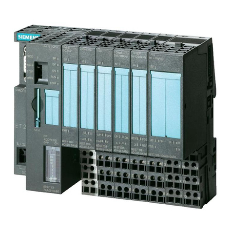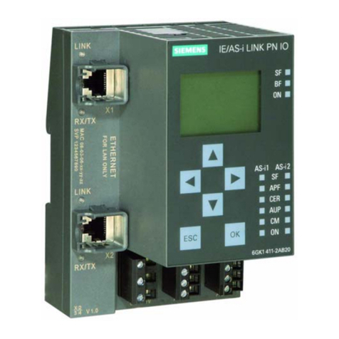
Digital input/Digital output module DIQ 16x24VDC/0.5A 8xM12 (6ES7143-5AH00-0BA0)
4Manual, 03/2019, A5E38688112-AC
Preface ................................................................................................................................................... 3
1 Documentation guide .............................................................................................................................. 6
2 Product overview .................................................................................................................................. 10
2.1 Properties............................................................................................................................... 10
2.2 Operator controls and display elements ................................................................................ 13
3 Configuration modes for digital inputs/outputs ....................................................................................... 14
3.1 Overview ................................................................................................................................ 14
3.2 Wiring ..................................................................................................................................... 15
3.2.1 Terminal and block diagram................................................................................................... 15
3.2.2 Pin assignment....................................................................................................................... 16
3.3 Parameters/address space .................................................................................................... 22
3.3.1 Parameters............................................................................................................................. 22
3.3.2 Explanation of the parameters............................................................................................... 23
3.3.3 Address space ....................................................................................................................... 24
3.4 Interrupts/diagnostic alarms................................................................................................... 27
3.4.1 Status and error displays ....................................................................................................... 27
3.4.2 Interrupts ................................................................................................................................ 29
3.4.3 Diagnostics alarms................................................................................................................. 29
4 Counting ............................................................................................................................................... 30
4.1 Configuration method 2xCount .............................................................................................. 32
4.1.1 Wiring ..................................................................................................................................... 32
4.1.1.1 Terminal and block diagram................................................................................................... 32
4.1.1.2 Pin assignment....................................................................................................................... 33
4.1.2 Parameters/address space .................................................................................................... 36
4.1.2.1 Parameters............................................................................................................................. 36
4.1.2.2 Explanation of the parameters ............................................................................................... 39
4.1.2.3 Assignment of the control interface........................................................................................ 43
4.1.2.4 Explanations on the control interface..................................................................................... 44
4.1.2.5 Assignment of the feedback interface.................................................................................... 45
4.1.2.6 Explanations for the feedback interface................................................................................. 46
4.1.3 Interrupts/diagnostic alarms................................................................................................... 48
4.1.3.1 Status and error displays ....................................................................................................... 48
4.1.3.2 Interrupts ................................................................................................................................ 50
4.1.3.3 Diagnostics alarms................................................................................................................. 51
