HPE Synergy 660 Gen9 User manual

HPE Synergy 660 Gen9 Compute Module
User Guide
Part Number: 813253-003
Published: July 2018
Edition: 3
Abstract
This document is for the person who installs, administers, and troubleshoots compute modules
and storage systems. Hewlett Packard Enterprise assumes you are qualified in the servicing of
computer equipment and trained in recognizing hazards in products with hazardous energy levels.

© Copyright 2016, 2018 Hewlett Packard Enterprise Development LP
Notices
The information contained herein is subject to change without notice. The only warranties for Hewlett Packard
Enterprise products and services are set forth in the express warranty statements accompanying such
products and services. Nothing herein should be construed as constituting an additional warranty. Hewlett
Packard Enterprise shall not be liable for technical or editorial errors or omissions contained herein.
Confidential computer software. Valid license from Hewlett Packard Enterprise required for possession, use,
or copying. Consistent with FAR 12.211 and 12.212, Commercial Computer Software, Computer Software
Documentation, and Technical Data for Commercial Items are licensed to the U.S. Government under
vendor's standard commercial license.
Links to third-party websites take you outside the Hewlett Packard Enterprise website. Hewlett Packard
Enterprise has no control over and is not responsible for information outside the Hewlett Packard Enterprise
website.
Acknowledgments
Intel®, Itanium®, Pentium®, Intel Inside®, and the Intel Inside logo are trademarks of Intel Corporation in the
United States and other countries.
Microsoft® and Windows® are either registered trademarks or trademarks of Microsoft Corporation in the
United States and/or other countries.
Adobe® and Acrobat® are trademarks of Adobe Systems Incorporated.
Java® and Oracle® are registered trademarks of Oracle and/or its affiliates.
UNIX® is a registered trademark of The Open Group.

Contents
Component identification........................................................................... 6
Front panel components......................................................................................................................6
Serial label pull tab information.................................................................................................6
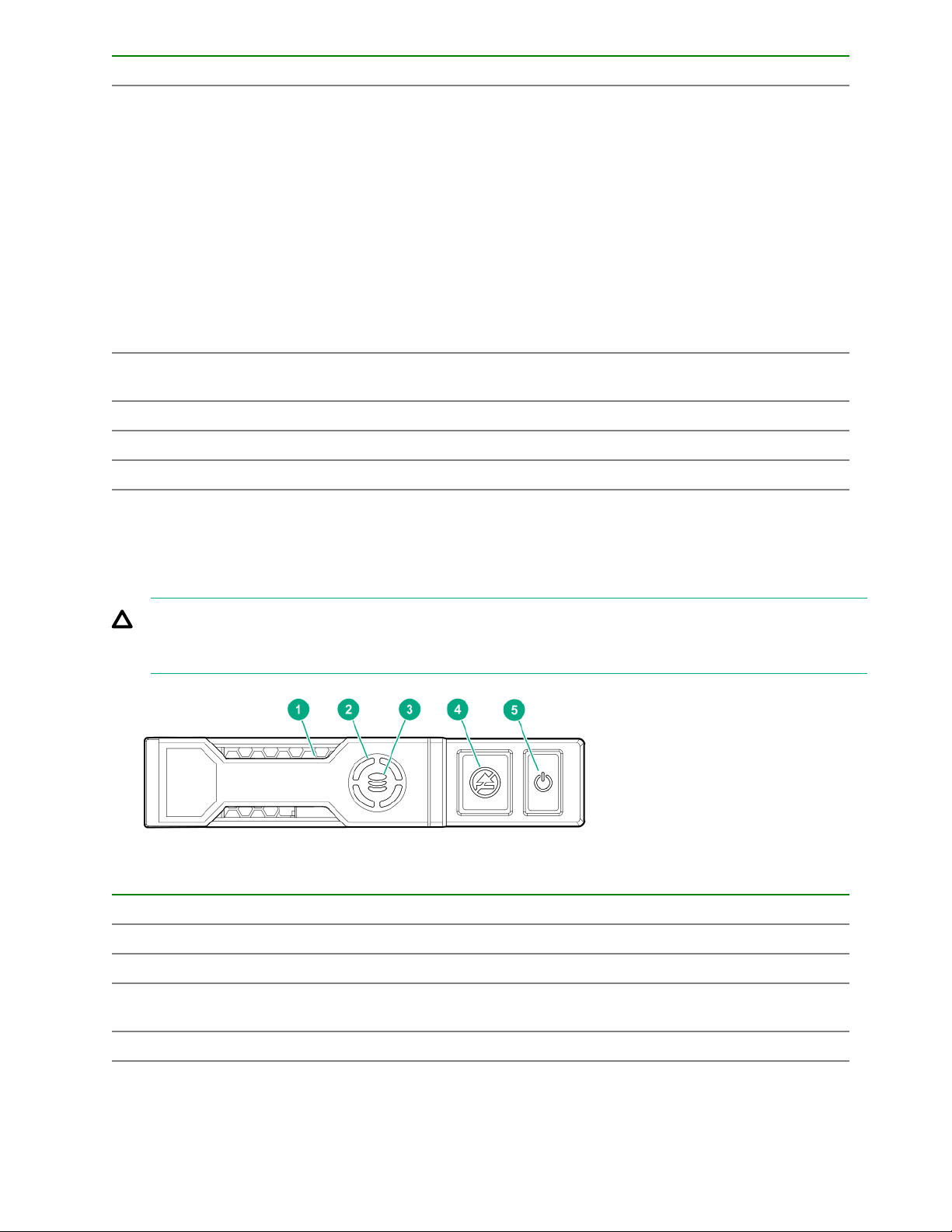
Front panel LEDs and buttons.............................................................................................................7
Drive numbering.................................................................................................................................. 8
Hot-plug drive LED definitions.............................................................................................................9
NVMe SSD LED definitions...............................................................................................................10
SFF flash adapter components and LED definitions......................................................................... 11
Front panel/drive cage numbering.....................................................................................................13
System board components................................................................................................................13
System maintenance switch................................................................................................... 14
Mezzanine connector definitions............................................................................................ 15
DIMM slot locations................................................................................................................ 16
Component and LED identification for HPE Synergy hardware........................................................ 16
Operations..................................................................................................17
Powering up the compute module ....................................................................................................17
Powering down the compute module ............................................................................................... 17
Removing the compute module ........................................................................................................17
Removing and replacing an access panel.........................................................................................18
Installing the access panel................................................................................................................ 19
Removing the DIMM baffles.............................................................................................................. 19
Installing the DIMM baffles................................................................................................................ 20
Removing the drive blank..................................................................................................................20
Removing the front panel/drive cage assembly.................................................................................21
Installing the front panel/drive cage assembly...................................................................................22
Setup...........................................................................................................23
Installation overview.......................................................................................................................... 23
Installing the compute module options.............................................................................................. 23
Installing the compute module ..........................................................................................................23
Completing the configuration.............................................................................................................25
Installing hardware options...................................................................... 26
Introduction........................................................................................................................................26
Installing SAS, SATA, or solid state drives........................................................................................ 26
Installing the SFF flash adapter.........................................................................................................27
Installing the controller.......................................................................................................................28
Installing the HPE Smart Storage Battery option...............................................................................29
Installing the mezzanine card options............................................................................................... 30
Memory options.................................................................................................................................32
SmartMemory......................................................................................................................... 33
Memory subsystem architecture.............................................................................................33
Single-, dual-, and quad-rank DIMMs .................................................................................... 33
DIMM identification ................................................................................................................ 33
Memory configurations........................................................................................................... 34
Contents 3

General DIMM slot population guidelines .............................................................................. 35
Preparing to install a DIMM.................................................................................................... 37
Installing a DIMM....................................................................................................................38
Installing the processor......................................................................................................................38
HPE Trusted Platform Module option................................................................................................ 42
Installing the Trusted Platform Module board......................................................................... 43
Retaining the recovery key/password.....................................................................................45
Enabling the Trusted Platform Module....................................................................................45
Cabling........................................................................................................47
Cabling resources..............................................................................................................................47
HPE Smart Storage Battery cabling.................................................................................................. 47
Dual NVMe-enabled backplane cabling............................................................................................ 47
HPE Smart Array P542D Controller cabling...................................................................................... 48
Removing and replacing the system battery.......................................... 49
Electrostatic discharge............................................................................. 51
Preventing electrostatic discharge.....................................................................................................51
Grounding methods to prevent electrostatic discharge..................................................................... 51
Specifications............................................................................................ 52
Environmental specifications ............................................................................................................52
Physical specifications.......................................................................................................................52
Documentation and troubleshooting resources for HPE Synergy....... 53
HPE Synergy documentation............................................................................................................ 53
HPE Synergy Configuration and Compatibility Guide.............................................................53
HPE Synergy Frame Link Module User Guide....................................................................... 53
HPE OneView User Guide for HPE Synergy..........................................................................53
HPE OneView Global Dashboard...........................................................................................53
HPE Synergy Image Streamer User Guide............................................................................ 53
HPE Synergy Image Streamer GitHub................................................................................... 54
HPE Synergy Software Overview Guide................................................................................ 54
HPE Synergy Firmware Update Overview..............................................................................54
Best Practices for HPE Synergy Firmware and Driver Updates............................................. 54
HPE OneView Support Matrix for HPE Synergy.....................................................................54
HPE Synergy Image Streamer Support Matrix....................................................................... 54
HPE Synergy Glossary...........................................................................................................54
HPE Synergy troubleshooting resources...........................................................................................54
Troubleshooting within HPE OneView....................................................................................55
HPE Synergy Troubleshooting Guide.....................................................................................55
Error Message Guide for HPE ProLiant Gen10 servers and HPE Synergy........................... 55
HPE OneView Help and HPE OneView API Reference......................................................... 55
HPE Synergy QuickSpecs......................................................................................................55
HPE Synergy document overview (documentation map)...................... 56
Support and other resources................................................................... 58
4Contents

Accessing Hewlett Packard Enterprise Support................................................................................ 58
Accessing updates............................................................................................................................ 58
Customer self repair.......................................................................................................................... 59
Remote support.................................................................................................................................59
Warranty information......................................................................................................................... 59
Regulatory information...................................................................................................................... 60
Documentation feedback...................................................................................................................60
Contents 5

Component identification
Front panel components
Item Description
1 Drive bay 1
2 Drive bay 21
3 Drive bay 3 1
4 Drive bay 41
5 External USB 3.0 connector (behind the serial label
pull tab)
6 Serial label pull tab
7 Compute module handle release latch
8 Compute module handle
Serial label pull tab information
The serial label pull tab is on the front panel of the compute module. To locate the serial label pull tab, see
Front panel components. The serial label pull tab provides the following information:
• Product serial number
• HPE iLO information
• QR code to mobile documentation
6 Component identification

Front panel LEDs and buttons
Item Description Status
1 UID LED Solid blue = Activated
Flashing blue (1 Hz/cycle per sec)
= Remote management or
firmware upgrade in progress
Off = Deactivated
2 Health status LED Solid green = Normal
Flashing green (1 Hz/cycle per
sec) = iLO is rebooting
Flashing amber = System
degraded
Flashing red (1 Hz/cycle per sec) =
System critical
3 Mezzanine NIC status LED Solid green= Link on any
Mezzanine NIC
Flashing green= Activity on any
Mezzanine NIC
Off = No link or activity on any
Mezzanine NIC
4 Power On/Standby button and
system power LED Solid green = System on
Flashing green (1 Hz/cycle per
sec) = Performing power on
sequence
Solid amber = System in standby
Off = No power present1
Front panel LEDs and buttons 7

1 If all other LEDs are off, then no power is present to the compute module. (For example, facility power is not present,
power cord is not attached, no power supplies are installed, power supply failure has occurred, or the compute module is
not properly seated.) If the health LED is flashing green while the system power LED is off, the Power On/Standby button
service is initializing or that an iLO reboot is in progress.
Drive numbering
Depending on the configuration, the drive bay numbering on this compute module will vary. Supported
configurations on this compute module are shown in the following table.
Compute module model Configuration Drive support
SAS model Standard backplane with
embedded controller or supported
controller option
Four SFF hot-plug SAS drive bays
with support for up to 4 SFF HDDs
or SSDs
SATA model Chipset SATA with embedded
controller or supported controller
option
Four SFF hot-plug SATA drive
bays with support for the following:
• Up to 4 SFF SATA HDDs or
SSDs
• Up to 8 uFF SATA HDDs (with
the SFF flash adapter for each
2 uFF drives)
Item SAS configuration SATA configuration* Expansion storage
configuration
1 1 Drive box 1, drive bay 1 and
101
Drive box 1, drive bay 1
2 2 Drive box 1, drive bay 2 and
102
Drive box 1, drive bay 2
Table Continued
8 Drive numbering

Item SAS configuration SATA configuration* Expansion storage
configuration
3 1 Drive box 2, drive bay 1 and
101
Drive box 2, drive bay 1
4 2 Drive box 2, drive bay 2 and
102
Drive box 2, drive bay 2
The driveless model is not shown, as it does not have drive bays and does support for any drives.
*SATA drives are supported only with the HPE Synergy 480 Gen9 Compute Module backplane.
Hot-plug drive LED definitions
Item LED Status Definition
1 Locate Solid blue The drive is being identified by a host application.
Flashing blue The drive carrier firmware is being updated or requires an update.
2 Activity
ring
Rotating green Drive activity
Off No drive activity
3 Do not
remove
Solid white Do not remove the drive. Removing the drive causes one or more of
the logical drives to fail.
Off Removing the drive does not cause a logical drive to fail.
4 Drive
status
Solid green The drive is a member of one or more logical drives.
Table Continued
Hot-plug drive LED definitions 9

Item LED Status Definition
Flashing green The drive is doing one of the following:
• Rebuilding
• Performing a RAID migration
• Performing a strip size migration
• Performing a capacity expansion
• Performing a logical drive extension
• Erasing
• Spare part activation
Flashing amber/
green
The drive is a member of one or more logical drives and predicts the
drive will fail.
Flashing amber The drive is not configured and predicts the drive will fail.
Solid amber The drive has failed.
Off The drive is not configured by a RAID controller or a spare drive.
NVMe SSD LED definitions
The NVMe SSD is a PCIe bus device. A device attached to a PCIe bus cannot be removed without allowing
the device and bus to complete and cease the signal/traffic flow.
CAUTION: Do not remove an NVMe SSD from the drive bay while the Do not remove LED is flashing.
The Do not remove LED flashes to indicate that the device is still in use. Removing the NVMe SSD
before the device has completed and ceased signal/traffic flow can cause loss of data.
Item LED Status Definition
1 Locate Solid blue The drive is being identified by a host application.
Flashing blue The drive carrier firmware is being updated or requires an update.
2 Activity
ring
Rotating green Drive activity
Off No drive activity
Table Continued
10 NVMe SSD LED definitions

Item LED Status Definition
3 Drive
status
Solid green The drive is a member of one or more logical drives.
Flashing green The drive is doing one of the following:
• Rebuilding
• Performing a RAID migration
• Performing a stripe size migration
• Performing a capacity expansion
• Performing a logical drive extension
• Erasing
Flashing amber/
green
The drive is a member of one or more logical drives and predicts the
drive will fail.
Flashing amber The drive is not configured and predicts the drive will fail.
Solid amber The drive has failed.
Off The drive is not configured by a RAID controller.
4 Do not
remove
Solid white Do not remove the drive. The drive must be ejected from the PCIe bus
prior to removal.
Flashing white The drive ejection request is pending.
Off The drive has been ejected.
5 Power Solid green Do not remove the drive. The drive must be ejected from the PCIe bus
prior to removal.
Flashing green The drive ejection request is pending.
Off The drive has been ejected.
SFF flash adapter components and LED definitions
SFF flash adapter components and LED definitions 11

Item Component Description
1 Locate
• Off—Normal
• Solid blue—The drive is being identified by a host application.
• Flashing blue—The drive firmware is being updated or requires
an update.
2 uFF drive ejection latch Removes the uFF drive when released.
3 Do not remove LED
• Off—OK to remove the drive. Removing the drive does not
cause a logical drive to fail.
• Solid white—Do not remove the drive. Removing the drive
causes one or more of the logical drives to fail.
4 Drive status LED
• Off—The drive is not configured by a RAID controller or a spare
drive.
• Solid green—The drive is a member of one or more logical
drives.
• Flashing green (4 Hz)—The drive is operating normally and has
activity.
• Flashing green (1 Hz)—The drive is rebuilding, erasing, or
performing a RAID migration, stripe size migration, capacity
expansion, logical drive extension, or spare activation.
• Flashing amber/green (1 Hz)—The drive is a member of one or
more logical drives that predicts the drive will fail.
• Solid amber—The drive has failed.
• Flashing amber (1 Hz)—The drive is not configured and predicts
the drive will fail.
5 Adapter ejection release latch
and handle
Removes the SFF flash adapter when released.
12 Component identification

Front panel/drive cage numbering
Item Drive cage number
1 1, 2
2 3, 4
System board components
Item Description
1 Internal USB 3.0 connector
2 System board handle
3 System battery
Table Continued
Front panel/drive cage numbering 13

Item Description
4 Drive backplane connector 1
5 Processor 1 DIMM slots (12)
6 Processor 3 DIMM slots (12)
7 Mezzanine connectors (M1–M6)
8 Management/power connector 1
9 Management/power connector 2
10 HPE Smart Storage Battery connector
11 Processor 4 DIMM slots (12)
12 Processor 2 DIMM slots (12)
13 System maintenance switch
14 Drive backplane connector 2
15 TPM connector
16 microSD card slot
17 External USB connector
System maintenance switch
Position Defa
ult
Function
S11Off Off = HPE iLO security is enabled.
On = HPE iLO security is disabled.
S2 Off Off = System configuration can be changed.
On = System configuration is locked.
S3 Off Reserved
S4 Off Reserved
S51Off Off = Power-on password is enabled.
On = Power-on password is disabled.
S61, 2Off Off = No function
On = Restore default manufacturing settings
S7 Off Off = Set default boot mode to UEFI.
On = Set default boot mode to legacy.
S8 — Reserved
S9 — Reserved
S10 — Reserved
Table Continued
14 System maintenance switch

Position Defa
ult
Function
S11 — Reserved
S12 — Reserved
1 You can access the redundant ROM by setting S1, S5, and S6 to On.
2 When the system maintenance switch position 6 is set to the On position, the system is prepared to restore all
configuration settings to their manufacturing defaults.
When the system maintenance switch position 6 is set to the On position and Secure Boot is enabled, some
configurations cannot be restored. For more information, see Secure Boot configuration.
IMPORTANT: Before using the S7 switch to change to Legacy BIOS Boot Mode, be sure the HPE
Dynamic Smart Array B140i Controller is disabled. Do not use the B140i controller when the compute
module is in Legacy BIOS Boot Mode.
Mezzanine connector definitions
Item Connector
identification
Supported
card types
Fabri
c
Supported ICM bays
1 Mezzanine
connector 1 (M1)
Type C and
Type D
1 ICM 1 and 4
2 Mezzanine
connector 2 (M2)1
Type C and
Type D
2 ICM 2 and 5
3 Mezzanine
connector 3 (M3)
Type C only 3 ICM 3 and 6
4 Mezzanine
connector 4 (M4)
Type C and
Type D
1 ICM 1 and 4
5 Mezzanine
connector 5 (M5)2
Type C and
Type D
2 ICM 2 and 5
6 Mezzanine
connector 6 (M6)
Type C 3 ICM 3 and 6
Mezzanine connector definitions 15

1 When installing a mezzanine option on mezzanine connector 2, processor 3 must be installed.
2 When installing a mezzanine option on mezzanine connector 5, processor 4 must be installed.
DIMM slot locations
DIMM slots are numbered sequentially (1 through 12) for each processor. The supported AMP modes use the
alpha assignments for population order, and the slot numbers designate the DIMM slot ID for spare
replacement.
The colored slots indicate the slot order within each channel:
• White — First slot of a channel
• Black — Second slot of a channel
• Blue — Third slot of a channel
The arrow points to the front of the compute module.
Component and LED identification for HPE Synergy
hardware
For more information about component and LED identification for HPE Synergy components, see the product-
specific maintenance and service guide or the HPE Synergy 12000 Frame Setup and Installation Guide in the
Hewlett Packard Enterprise Information Library .
16 DIMM slot locations

Operations
Powering up the compute module
To power up the compute module, press the Power On/Standby button after the power button LED has turned
amber.
Powering down the compute module
Before powering down the compute module for any upgrade or maintenance procedures, perform a backup of
the system and all data. Then, shut down, as appropriate, applications and operating systems. A successful
shutdown is indicated by the system power LED displaying amber.
IMPORTANT: Always attempt a graceful shutdown before forcing a nongraceful shutdown. Application
data can be lost when performing a nongraceful shutdown of applications and the OS.
Before proceeding, verify the following:
• The compute module is in standby mode by observing that the system power LED is amber.
• The UID LED is not flashing blue.
NOTE:
◦ When the compute module is in standby mode, auxiliary power is still being provided to the system.
◦ If the UID LED is flashing blue, a remote session is in progress.
To power down the compute module, use one of the following methods:
• To perform a graceful shutdown of applications and the OS when powering down the compute module to
standby mode, do one of the following:
◦ Press and release the Power On/Standby button.
◦ Select the Momentary press power off selection in HPE OneView.
◦ Select the Momentary press virtual power button selection in HPE iLO.
• If a graceful shutdown fails to power down the compute module to standby mode when an application or
OS stops responding, force a nongraceful shutdown of applications and the OS. Do one of the following:
◦ Press and hold the Power On/Standby button for more than four seconds.
◦ Select the Press and hold power off selection in HPE OneView.
◦ Select the Press and hold virtual power button selection in HPE iLO.
Removing the compute module
Operations 17

Procedure
1. Identify the proper compute module.
2. Power down the compute module.
3. Remove the compute module.
4. Place the compute module on a flat, level work surface.
WARNING: To reduce the risk of personal injury from hot surfaces, allow the drives and the internal
system components to cool before touching them.
CAUTION: To prevent damage to electrical components, properly ground the compute module
before beginning any installation procedure. Improper grounding can cause ESD.
Removing and replacing an access panel
Procedure
1. Power down the compute module.
2. Remove the compute module.
3. Press the access panel release button.
4. Slide the access panel towards the rear of the compute module, and then lift to remove the panel.
18 Removing and replacing an access panel

To replace the component, reverse the removal procedure.
Installing the access panel
Procedure
1. Place the access panel on top of the compute module.
2. Slide the access panel forward until it clicks into place.
Removing the DIMM baffles
Procedure
1. Power down the compute module.
2. Remove the compute module.
3. Place the compute module on a flat, level work surface.
4. Remove the access panel.
5. When removing the center baffle, disconnect the HPE Smart Storage Battery cable if installed. For more
information, see "Smart Storage Battery cabling."
6. Remove one or more DIMM baffles.
Installing the access panel 19

Installing the DIMM baffles
Procedure
1. Install the DIMM baffles.
2. Connect the HPE Smart Storage battery cable, if installing. For more information, see "Smart Storage
Battery cabling."
3. Install the access panel.
4. Install the compute module.
Removing the drive blank
Remove the component as indicated.
20 Installing the DIMM baffles
Table of contents
Other HPE Control Unit manuals

HPE
HPE AQUA AAC01 Series User manual

HPE
HPE Synergy 620 Gen9 User manual

HPE
HPE SFP28 User manual

HPE
HPE G2 R5000 Assembly instructions

HPE
HPE X130 10G SFP+ LC LRM User manual

HPE
HPE JH182A User manual

HPE
HPE StoreEver MSL3040 User manual

HPE
HPE Moonshot 45Gc User manual

HPE
HPE Synergy D3940 Assembly instructions

HPE
HPE LSWM124XG2Q User manual