Stageline LMS-808 User manual

MIKROFON-LINE-MISCHER/
LINE-SPLITTER
MICROPHONE LINE MIXER/LINE SPLITTER
MIXEUR LIGNE MICRO/RÉPARTITEUR LIGNE
MISCELATORE MICROFONO-LINE/LINE SPLITTER
LMS-808 Best.-Nr. 20.2160
LEFT RIGHT
010010
LEVEL
PRO 6-CHANNEL
MIC/LINE MIXER
LINE SPLITTER
LMS-808
MIXER
ON
LEDS:
GREEN– SIGNAL
RED– PEAK
STEREO OUT
LEVEL
LR
010
STEREO IN
10 |RL|0
LEVEL PAN
1
CH
LINE
MIC
MIX
SPLIT
10 |RL|0
LEVEL PAN
2
CH
LINE
MIC
MIX
SPLIT
10 |RL|0
LEVEL PAN
3
CH
LINE
MIC
MIX
SPLIT
10 |RL|0
LEVEL PAN
4
CH
LINE
MIC
MIX
SPLIT
10 |RL|0
LEVEL PAN
5
CH
LINE
MIC
MIX
SPLIT
10 |RL|0
LEVEL PAN
6
CH
LINE
MIC
MIX
SPLIT
POWER
SIG./PK SIG./PK SIG. /PK SIG./ PK SIG./PK SIG. /PK SIG./ PK SIG./PK
LEVEL
LR
BEDIENUNGSANLEITUNG • INSTRUCTION MANUAL • MODE D’EMPLOI • ISTRUZIONI PER L’USO
MANUAL DE INSTRUCCIONES • INSTRUKCJA OBSŁUGI • VEILIGHEIDSVOORSCHRIFTEN
SIKKERHEDSOPLYSNINGER • SÄKERHETSFÖRESKRIFTER • TURVALLISUUDESTA

2wwwwww..iimmggssttaaggeelliinnee..ccoomm
Voordat u inschakelt ...
Wij wensen u veel plezier met uw nieuw toestel van “img
Stage Line”. Lees de veiligheidsvoorschriften, alvorens
het toestel in gebruik te nemen. Door de veiligheidsvoor-
schriften op te volgen zal een slechte werking vermeden
worden, en zal een eventueel letsel aan uzelf en schade
aan uw toestel tengevolge van onzorgvuldig gebruik
worden voorkomen.
U vindt de veiligheidsvoorschriften op pagina 16.
Bevor Sie einschalten ...
Wir wünschen Ihnen viel Spaß mit Ihrem neuen Gerät von
„img Stage Line“. Dabei soll Ihnen diese Bedienungsan-
leitung helfen, alle Funktionsmöglichkeiten kennen zu ler-
nen. Die Beachtung der Anleitung vermeidet außerdem
Fehlbedienungen und schützt Sie und Ihr Gerät vor even-
tuellen Schäden durch unsachgemäßen Gebrauch.
Den deutschen Text finden Sie auf den Seiten 4–7.
Before you switch on ...
We wish you much pleasure with your new “img Stage
Line” unit. With these operating instructions you will be
able to get to know all functions of the unit. By following
these instructions false operations will be avoided, and
possible damage to yourself and your unit due to im-
proper use will be prevented.
You will find the English text on the pages 4–7.
D
A
CH
GB
Przed uruchomieniem ...
Życzymy zadowolenia z nowego produktu “img Stage
Line”. Dzięki tej instrukcji obsługi będą Państwo w
stanie poznać wszystkie funkcje tego urządzenia.
Stosując się do instrukcji unikną Państwo błędów i
ewentualnego uszkodzenia urządzenia na skutek nie-
prawidłowego użytkowania.
Tekst polski znajduje się na stronach 12 – 15.
PL
B
NL
Antes de cualquier instalación ...
Tenemos de agradecerle el haber adquirido un aparato
“img Stage Line” y le deseamos un agradable uso. Este
manual quiere ayudarle a conocer las multiples facetas
de este aparato. La observación de las instrucciones
evita operaciones erróneas y protege Vd. y vuestro apa-
rato contra todo daño posible por cualquier uso inade-
cuado.
La versión española se encuentra en las páginas 12–15.
Inden De tænder for apparatet ...
Vi ønsker Dem god fornøjelse med Deres nye “img
Stage Line” apparat. Læs oplysningerne for en sikker
brug af apparatet før ibrugtagning. Følg sikkerhedsop-
lysningerne for at undgå forkert betjening og for at be-
skytte Dem og Deres apparat mod skade på grund af for-
kert brug.
Sikkerhedsoplysningerne finder De på side 16.
E
DK
Förskrift
Vi önskar dig mycket nöje med din nya enhet från “img
Stage Line”. Läs gärna säkerhetsinstruktionerna innan
du använder enheten. Genom att följa säkerhetsinstruk-
tionerna kan många problem undvikas, vilket annars kan
skada enheten.
Du finner säkerhetsinstruktionerna på sidan 16.
SFIN
Avant toute mise en service ...
Nous vous remercions d’avoir choisi un appareil “img
Stage Line” et vous souhaitons beaucoup de plaisir à
l’utiliser. Cette notice a pour objectif de vous aider à
mieux connaître les multiples facettes de l’appareil. En
outre, en respectant les conseils donnés, vous éviterez
toute mauvaise manipulation de sorte que vous-même et
votre appareil soient protégés de tout dommage.
La version française se trouve pages 8–11.
Prima di accendere ...
Vi auguriamo buon divertimento con il Vostro nuovo
apparecchio “img Stage Line”. Le istruzioni per l’uso Vi
possono aiutare a conoscere tutte le possibili funzioni. E
rispettando quanto spiegato nelle istruzioni, evitate di
commettere degli errori, e così proteggete Voi stessi, ma
anche l’apparecchio, da eventuali rischi per uso impro-
prio.
Il testo italiano lo potete trovare alle pagine 8–11.
F
B
CH
I
Ennen virran kytkemistä ...
Toivomme, että uusi “img Stage Line”-laitteesi tuo sinulle
paljon iloa ja hyötyä. Ole hyvä ja lue käyttöohjeet ennen
laitteen käyttöönottoa. Luettuasi käyttöohjeet voit käyt-
tää laitetta turvallisesti ja vältyt laitteen väärinkäytöltä.
Käyttöohjeet löydät sivulta 17.

3
34567 8910
12
➁
11 12 13 14 15
CH 6
OUT IN
STEREO OUT
RL CH 5
OUT CH 2 IN CH 1
OUT IN STEREO IN
RL
MAINS
230V~/
50Hz
CH5
21
3
12
312
312
312
321
321
3
12
321
321
3
1
2
3SIG
PEAK
IN
LEVEL LEVEL
OUT
1
2
3
1
2
3
LEVEL LEVEL
+12 V PHANTOM
1
2
3
IN
MIX
PAN
LEVEL
CHANNEL 1
STEREO CHANNEL
MIX
OUT
L
R
R
MIC
LINE
SPLIT
MIC
LINE
ON OFF
OFF ON
SIG
PEAK
SIG
PEAK
SIG
PEAK
1
2
3L
1
2
3
SIG
PEAK
CHANNEL 2
-
6
➂
➀

Bitte klappen Sie die Seite 3 heraus. Sie sehen
dann immer die beschriebenen Bedienelemente
und Anschlüsse.
1Übersicht der Bedienelemente und
Anschlüsse
1.1 Frontseite (Abb. 1)
1LEDs für den Signalpegel
grün = Eingangsignal vorhanden
rot = Eingangsignal übersteuert
2Betriebsanzeige
3Regler LEVEL der Vorverstärkung für den linken
und rechten Kanal
4Umschalttaste, jeweils für die Mono-Kanäle 1–6,
um den Regelbereich für die Level-Regler (5) an
die jeweils angeschlossene Signalquelle anzu-
passen.
Bei angeschlossener Line-Quelle die Taste aus-
rasten (Stellung „LINE“):
Der Regelbereich beträgt
-
∞bis +20dB
Bei angeschlossenem Mikrofon die Taste einras-
ten (Stellung „MIC“):
Der Regelbereich beträgt
-
∞bis +60dB
5Vorderer Drehknopf LEVEL, jeweils für die
Kanäle CH1 bis CH6
Betriebsart SPLIT: Zum Einstellen des Kanalpe-
gels der Ausgänge CH1 bis CH6
Betriebsart MIXER: Zum Einstellen des Anteils
des jeweiligen Kanals am Gesamtsignal amAus-
gang STEREO OUT (12); der hier eingestellte
Signalpegel liegt gleichzeitig am jeweiligen Aus-
gang (13) des Kanals an.
6Hinterer Drehknopf PAN, jeweils für die Kanäle
CH1 bis CH6
Betriebsart SPLIT: Mit dem Regler wird das Ver-
hältnis zwischen dem linken und rechten Kanal
des Stereo-Eingangssignals im jeweiligen Aus-
gang (13) eingestellt.
Betriebsart MIXER: Regler zum Platzieren des
Mono-Eingangssignals in der Stereo-Basis des
Ausgangssignals
7Umschalttaste MIX/SPLIT, jeweils für die Mono-
Kanäle CH1 bis CH6, um die Betriebsart zu
wählen:
Taste ausgerastet: Betriebsart MIX
Taste eingerastet: Betriebsart SPLIT
8Umschalttaste MIXER ON:
Taste eingerastet: Der Mixer-Betrieb ist einge-
schaltet. Arbeiten die jeweiligen Mono-Kanäle
CH1 bis CH6 im Mixerbetrieb, so werden deren
Kanalpegel auf den Masterkanal „STEREO
OUT“ gegeben.
Taste ausgerastet: Der Mixerbetrieb ist ausge-
schaltet. Sind die jeweiligen Mono-Kanäle CH1
bis CH6 auf „MIX“ geschaltet, so arbeiten diese
als separate Verstärker.
9Regler LEVELSTEREO OUT zum Einstellen des
Pegels an den Ausgängen STEREO OUT (12)
10 Ein-/Ausschalter POWER
1.2 Rückseite (Abb. 2)
11 Netzkabel zum Anschluss an eine Steckdose
(230V~/50Hz)
12 Stereo-Ausgang (2xXLR, symmetrisch)
13 Mono-Ausgang der Kanäle CH1 bis CH6
(XLR, symmetrisch)
14 Mono-Eingang der Kanäle CH1 bis CH6
(XLR, symmetrisch)
15 Stereo-Eingang (2xXLR, symmetrisch)
2Hinweise für den sicheren Gebrauch
Dieses Gerät entspricht der Richtlinie für elektro-
magnetische Verträglichkeit 89/336/EWG und der
Niederspannungsrichtlinie 73/23/EWG.
Beachten Sie auch unbedingt die folgenden Punkte:
●Das Gerät ist nur zur Verwendung im Innenbe-
reich geeignet. Schützen Sie es vor Tropf- und
Spritzwasser, hoher Luftfeuchtigkeit und Hitze
(zulässiger Einsatztemperaturbereich 0–40°C).
●Stellen Sie keine mit Flüssigkeit gefüllten Gefäße,
z.B. Trinkgläser, auf das Gerät.
●Nehmen Sie das Gerät nicht in Betrieb bzw. ziehen
Sie sofort den Netzstecker aus der Steckdose:
1. wenn sichtbare Schäden am Gerät oder an der
Netzanschlussleitung vorhanden sind,
2. wenn nach einem Sturz oder Ähnlichem der
Verdacht auf einen Defekt besteht,
3. wenn Funktionsstörungen auftreten.
Lassen Sie das Gerät in jedem Fall in einer Fach-
werkstatt reparieren.
●Ziehen Sie den Netzstecker nie am Kabel aus der
Steckdose, fassen Sie immer am Stecker an.
●Eine beschädigte Netzanschlussleitung darf nur
durch den Hersteller oder eine autorisierte Fach-
werkstatt ersetzt werden.
●Verwenden Sie für die Reinigung nur ein trockenes,
weiches Tuch, niemals Wasser oder Chemikalien.
●Wird das Gerät zweckentfremdet, nicht richtig an-
geschlossen, falsch bedient oder nicht fachgerecht
repariert, kann keine Haftung für daraus resultie-
rende Sach- oder Personenschäden und keine
Garantie für das Gerät übernommen werden.
Soll das Gerät endgültig aus dem Be-
trieb genommen werden, übergeben Sie
es zur umweltgerechten Entsorgung
einem örtlichen Recyclingbetrieb.
Achtung! Das Gerät wird mit lebensgefährlicher
Netzspannung (230V~) versorgt. Nehmen Sie
deshalb niemals selbst Eingriffe am Gerät vor, die
nicht in dieser Anleitung beschrieben sind. Durch
unsachgemäßes Vorgehen besteht die Gefahr
eines elektrischen Schlages.
Please unfold page 3. Then you can always see the
operating elements and connections described.
1Operating Elements and Connections
1.1 Front panel (fig. 1)
1LEDs for the signal level
green = input signal is available
red = input signal is overloaded
2POWER LED
3Controls LEVEL of the preamplification for the
left channel and the right channel
4Selector button, each for the mono channels 1 to
6, to adapt the control range for the level controls
(5) to the signal source connected in each case.
With a line source connected, disengage the but-
ton (position “LINE”):
The control range is
-
∞up to +20dB
With a microphone connected, engage the but-
ton (position “MIC”):
The control range is
-
∞up to +60dB
5Front rotary knob LEVEL, each for the channels
CH1 to CH6
Operating mode SPLIT: To adjust the channel
level of the outputs CH1 to CH6
Operating mode MIXER: To adjust the part of the
respective channel of the total signal at the out-
put STEREO OUT (12); the signal level adjusted
at this output is at the same time present at the
respective output (13) of the channel.
6Rear rotary knob PAN, each for the channels
CH1 to CH6
Operating mode SPLIT: With the control the ratio
is adjusted between the left channel and the right
channel of the stereo input signal in the respec-
tive output (13).
Operating mode MIXER: Control for placing the
mono input signal in the stereo base of the out-
put signal
7Selector button MIX/SPLIT, each for the mono
channels CH1 to CH6 to select the operating
mode:
Button disengaged: operating mode MIX
Button engaged: operating mode SPLIT
8Selector button MIXER ON:
Button engaged: The mixer mode is switched on.
If the respective mono channels CH1 to CH6
operate in mixer mode, their channel levels are
fed to the master channel “STEREO OUT”.
Button disengaged: The mixer mode is switched
off. If the respective mono channels CH 1 to
CH6 are switched to “MIX”, they operate as
separate amplifiers.
9Control LEVEL STEREO OUT for adjusting the
level at the outputs STEREO OUT (12)
10 POWER switch
1.2 Rear panel (fig. 2)
11 Mains cable for connection to a mains socket
(230V~/50Hz)
12 Stereo output (2 x XLR, balanced)
13 Mono output of the channels CH1 to CH6
(XLR, balanced)
14 Mono input of the channels CH1 to CH6
(XLR, balanced)
15 Stereo input (2 x XLR, balanced)
2Safety Notes
This unit corresponds to the directive 89/336/EEC
for electromagnetic compatibility and to the low volt-
age directive 73/23/EEC.
It is essential to observe the following items:
●The unit is suitable for indoor use only. Protect it
against dripping water and splash water, high air
humidity, and heat (admissible ambient tempera-
ture range 0–40°C).
●Do not place any vessels filled with liquid, e.g.
drinking glasses, on the unit.
●Do not set the unit into operation, and immediately
disconnect the mains plug from the mains socket
if
1. there is visible damage to the unit or to the
mains cable,
2. a defect might have occurred after a drop or
similar accident,
3. malfunctions occur.
The unit must in any case be repaired by skilled
personnel.
●Never pull the mains cable to disconnect the
mains plug from the mains socket, always seize
the plug.
●Adamaged mains cable must only be replaced by
the manufacturer or by authorized, skilled person-
nel.
●For cleaning only use a dry, soft cloth, by no
means chemicals or water.
●No guarantee claims for the unit and no liability for
any resulting personal damage or material
damage will be accepted if the unit is used for
other purposes than originally intended, if it is not
correctly connected, operated, or not repaired in
an expert way.
●Important for U.K. Customers!
The wires in this mains lead are coloured in
accordance with the following code:
blue = neutral
brown = live
As the colours of the wires in the mains lead of this
appliance may not correspond with the coloured
markings identifying the terminals in your plug,
proceed as follows:
Attention! The unit is supplied with hazardous
mains voltage (230V~). Leave servicing to skilled
personnel only. Never make any modification on
the unit not described in this instruction manual.
Inexpert handling may cause an electric shock
hazard.
4
GB
D
A
CH

3Einsatzmöglichkeiten
Der Mikrofon-Line-Mischer/Line-Splitter ist auf-
grund seines Konzepts für vielfältige Audio-Anwen-
dungen einsetzbar. Im Splitter-Betrieb lässt sich ein
Stereo-Eingangssignal auf je sechs Mono-Aus-
gänge verteilen, wobei über Pan-Regler der Sig-
nalanteil des Stereo-Signals für jeden Kanal indivi-
duell einstellbar ist. Im Mixer-Betrieb können ein
Stereo-Signal und maximal sechs Mono-Signale mit
Mikrofon- oder Line-Pegel auf einen Stereo-Aus-
gang gemischt werden. Die sechs Mono-Kanäle
sowie der Stereo-Kanal können auch als separate
Verstärker zur Pegel- oder Impedanzanpassung
genutzt werden.
4Aufstellmöglichkeiten
Das Gerät ist für die Montage in ein Rack
(482mm/19") vorgesehen, kann aber auch als frei-
stehendes Tischgerät verwendet werden. Für den
Einbau in ein Rack wird 1HE (Höheneinheit) =
44,45mm benötigt.
5Geräte anschließen
Vor dem Neuanschluss oder dem Verändern
bestehender Anschlüsse den Mikrofon-Line-
Mischer/Line-Splitter und die anzuschließenden
Geräte ausschalten.
1) Stereo-Gerät mit Line-Pegel (z.B. CD-Spieler,
Mischpult usw.) an die XLR-Buchsen STEREO
IN (15) anschließen.
2) An die Eingänge der Mono-Kanäle CH1 bis CH6
(14) können sowohl Mikrofone als auch Mono-
Geräte mit Line-Pegel angeschlossen werden.
3) Die Endverstärker für die Lautsprecher oder
nachfolgende Geräte mit Line-Pegel können je
nach Konfiguration an die XLR-Buchsen
CH1–CH6 OUT (13) und STEREO OUT (12)
angeschlossen werden.
5.1 Mikrofon-Phantomspeisung dazuschalten
Um auch phantomgespeiste Mikrofone betreiben zu
können, lässt sich für jeden der sechs Mono-Kanäle
getrennt eine 12-V-Phantomspeisung dazuschalten.
1) Den Netzstecker aus der Steckdose ziehen.
2) Den Gehäusedeckel abschrauben.
3) Für die gewünschten Kanäle die entsprechenden
Steckbrücken JP101 (für Kanal CH1) bis JP601
(für Kanal CH6) von „OFF“ nach „ON“ um-
stecken.
4) Den Gehäusedeckel wieder festschrauben.
5) Es wird empfohlen, die Eingangsbuchsen der
mit Phantomspeisung beschalteten Kanäle ent-
sprechenden zu kennzeichnen!
6Bedienung
1) Vor dem Einschalten sollten alle Ausgangsregler
(5 und 9) auf Minimum gestellt werden, um Ein-
schaltgeräusche zu vermeiden.
2) Das Gerät mit dem Schalter POWER (10) ein-
schalten. Zur Anzeige der Betriebsbereitschaft
leuchtet die rote LED (2) über dem Schalter. An-
schließend die angeschlossenen Geräte ein-
schalten.
Achtung! Zum Zuschalten der Phantomspeisung
muss das Gerät geöffnet werden. Darum darf dies
nur durch eine qualifizierte Fachkraft erfolgen.
Vorsicht! Ist die Phantomspeisung dazugeschal-
tet, dürfen keine asymmetrisch beschalteten
Mikrofone oder Geräte mit Linepegel an den ent-
sprechenden Eingang angeschlossen werden.
Andernfalls können diese Mikrofone und Geräte
beschädigt werden.
1. The wire which is coloured blue must be con-
nected to the terminal in the plug which is
marked with the letter Nor coloured black.
2. The wire which is coloured brown must be con-
nected to the terminal which is marked with the
letter Lor coloured red.
3Applications
Due to its concept, the microphone line mixer/line
splitter can be used for versatile audio applications.
In the splitter mode it is possible to distribute a stereo
input signal to six mono outputs each, in which case
the signal part of the stereo signal can be adjusted
individually for each channel via pan controls. In the
mixer mode a stereo signal and a maximum of six
mono signals with microphone or line level can be
mixed to a stereo output. The six mono channels as
well as the stereo channel can also be used as sepa-
rate amplifiers for level or impedance matching.
4Setting Up
The unit is provided for mounting into a rack
(482mm/19") but it can also be used as a table top
unit. For the installation into a rack one rack space
(height unit) = 44.45mm is required.
5Connecting the Units
Prior to the new connection or change of existing
connections switch off the microphone line mixer/
line splitter and the units to be connected.
1) Connect a stereo unit with line level (e.g. CD play-
er, mixer, etc.) to the XLR jacks STEREO IN (15).
2) It is possible to connect both microphones and
mono units with line level to the inputs of the
mono channels CH1 to CH6 (14).
3) The power amplifiers for the speakers or subse-
quent units with line level can be connected to
the XLR jacks CH1 to CH6 OUT (13) and STER-
EO OUT (12) depending on their configuration.
5.1 Switching on the microphone phantom
power
To be able to operate also phantom-powered micro-
phones, it is possible to switch on a 12 V phantom
power separately for each of the six mono channels.
1) Disconnect the mains plug from the mains
socket.
2) Unscrew the housing cover.
3) For the desired channels, rearrange the corre-
sponding jumpers JP 101 (for channel CH1) to
JP 601 (for channel CH6) from “OFF” to “ON”.
4) Tightly screw the housing cover again.
5) It is recommended to mark the input jacks of the
channels provided with phantom power accord-
ingly!
6Operation
1) Prior to switching on, all output controls (5 and 9)
should be set to minimum to prevent switching
noise.
2) Switch on the unit with the POWER switch (10).
To indicate that the unit is ready for operation, the
red LED (2) above the switch lights up. Then
switch on the connected units.
Attention! To switch on the phantom power, the
unit must be opened. Therefore, this must only be
made by qualified expert personnel.
Caution! If the phantom power is switched on, no
unbalanced microphones or units with line level
must be connected to the corresponding input.
Otherwise, these microphones and units may be
damaged.
If the unit is to be put out of operation de-
finitively, take it to a local recycling plant
for a disposal which is not harmful to the
environment.
5
GB
D
A
CH

6.1 Betriebsart Mixer (Abb. 4)
In der Betriebsart Mixer können ein Stereo-Kanal
und bis zu sechs Mono-Kanäle auf einen Stereo-
Ausgangskanal gemischt werden.
1) Die Umschalttaste MIX/SPLIT (7) für den jeweili-
gen Kanal einrasten sowie die Umschalttaste
MIXERON (8) einrasten.
2) Den Regler LEVEL STEREO OUT (9) so weit
aufdrehen, dass das Mischungsverhältnis der
angeschlossenen Tonquellen optimal eingestellt
werden kann.
3) Mit den Umschalttasten LINE/MIC (4) die Mono-
Kanäle CH1–CH6 auf die angeschlossenen
Quellen einstellen. Bei angeschlossenem Mikro-
fon die Umschalttaste einrasten und bei Geräten
mit Line-Pegel ausrasten.
4) Mit den Reglern LEVEL STEREO IN (3) und den
Kanalreglern LEVEL CH1–CH6 (5) das
gewünschte Lautstärkeverhältnis einstellen: Die
Tonquellen, die am lautesten zu hören sein sol-
len, so aussteuern, dass die entsprechende LED
(1) bei der lautesten Musikpassage kurz rot
leuchtet.
5) Mit den Reglern PAN (6) der Mono-Kanäle
CH1–CH6 das Mono-Kanalsignal wie ge-
wünscht in der Stereo-Basis platzieren.
6) Mit dem Regler LEVEL STEREO OUT (9) den
endgültigen Pegel des Stereo-Mastersignals ein-
stellen.
6.2 Betriebsart Splitter (Abb. 5)
Im Betriebsmodus Splitter lässt sich ein Stereo-Sig-
nal auf sechs Mono-Kanäle und einen Stereo-Kanal
verteilen. Bei den Mono-Kanälen lassen sich die
Signalanteile des Stereo-Signals mit den PAN-Reg-
lern individuell einstellen. Bei dem Stereo-Aus-
gangskanal ist keine freie Zuordnung möglich, das
linke Eingangssignal ist dem linken Ausgangssignal
zugeordnet und das rechte Eingangssignal ist dem
rechten Ausgangssignal zugeordnet.
1) Die Umschalttaste MIX/SPLIT (7) für den jeweili-
gen Kanal ausrasten.
2) Mit den Reglern INPUT LEVEL (3) den Ein-
gangspegel des Stereo-Signals so einstellen,
dass die LEDs (1) bei der lautesten Musikpas-
sage kurz rot leuchten.
3) Für die sechs Mono-Kanäle mit den PAN-Reglern
(6) den gewünschten Signalanteil des Stereo-
Signals einstellen.
4) Mit den Reglern LEVEL CH1–CH6 (5) die Pegel
der Mono-Kanäle individuell einstellen.
5) Mit den Reglern LEVEL STEREO OUT (9) den
Pegel des Stereo-Ausgangssignals einstellen.
6.3 Betriebsart 8-Kanal-Verstärker (Abb. 6)
In dieser Betriebsart arbeiten die Kanäle als unab-
hängige Verstärker, die ein niederohmiges, symme-
trisches Ausgangssignal liefern. Die sechs Mono-
Kanäle und der Stereo-Kanal können einzeln im
Pegel angepasst werden. Die Pegelanpassung ist
z.B. notwendig, wenn eine Signalquelle einen zu
geringenAusgangspegel hat, um ein nachfolgendes
Gerät auszusteuern. In dieser Betriebsart kann das
Gerät auch als 6fach-Mikrofonvorverstärker genutzt
werden.
1) Die Umschalttaste MIX/SPLIT (7) für den jeweili-
gen Kanal einrasten sowie die Umschalttaste
MIXERON (8) ausrasten.
2) Mit den Umschalttasten LINE/MIC (4) die Mono-
Kanäle CH1–CH6 auf die angeschlossenen
Quellen einstellen. Bei angeschlossenem Mikro-
fon die Umschalttaste einrasten und bei Geräten
mit Line-Pegel ausrasten.
3) Bei den Mono-Kanälen mit den Reglern LEVEL
CH1–CH6 (5) den gewünschten Pegel einstel-
len.
4) Bei dem Stereo-Kanal den Regler LEVEL STE-
REO OUT (9) auf Maximum stellen.
5) Mit den Reglern LEVEL STEREO IN (3) für den
linken und rechten Kanal den gewünschten
Pegel individuell einstellen.
6.4 Kombinierte Betriebsarten
Werden in der Betriebsart Splitter nicht alle sechs
Mono-Kanäle als Ausgänge benötigt, können die
übrigen Kanäle als einzelne unabhängige Verstär-
ker betrieben werden. Siehe Kapitel 6.3.
7Technische Daten
Eingänge
(Eingangsempfindlichkeit bei 1V Ausgangspegel,
Eingangsimpedanz)
STEREO IN: . . . . . . . . . . 250mV, 30kΩ
XLR, symmetrisch
CH1–CH6: . . . . . . . . . . . Line 100mV, 40kΩ
umschaltbar auf
Mic 1mV, 6,6kΩ
XLR, symmetrisch
Phantomspeisung: . . . . . 12V (intern schaltbar)
Ausgänge
(Nennpegel, Ausgangsimpedanz)
STEREO OUT: . . . . . . . . 1V, 200Ω
XLR, symmetrisch
CH1–CH6: . . . . . . . . . . . 1V, 200Ω
XLR, symmetrisch
Frequenzbereich: . . . . . . . . 10Hz–30000Hz
(+0/
-
0,5dB)
Klirrfaktor: . . . . . . . . . . . . . . 0,02%
Störabstand: . . . . . . . . . . . . 81dB, bewertet
Übersprechen: . . . . . . . . . .
-
63dB (1kHz)
Stromversorgung: . . . . . . . . 230V~/50Hz/10VA
Einsatztemperatur: . . . . . . . 0–40°C
Abmessungen (B x H X T): . 482 x 48 x 205mm,
1Höheneinheit
Gewicht: . . . . . . . . . . . . . . . 2,9kg
Änderungen vorbehalten.
6.1 Mixer mode (fig. 4)
In the mixer mode a stereo channel and up to six
mono channels can be mixed to a stereo output
channel.
1) Engage the selector button MIX/SPLIT (7) for the
respective channel and engage the selector but-
ton MIXER ON (8).
2) Turn up the control LEVEL STEREO OUT (9) so
that the mixing ratio of the connected audio
sources can be adjusted in an optimum way.
3) With the selector buttons LINE/MIC (4) adjust the
mono channels CH1 to CH6 to the connected
sources. In case of a microphone connected
engage the selector button, and in case of units
with line level disengage it.
4) With the controls LEVEL STEREO IN (3) and the
channel controls LEVEL CH1 to CH6 (5) adjust
the desired volume ratio: Control the levels of the
audio sources to be heard at highest volume so
that the corresponding LED (1) shortly lights up
with the music passage of the highest volume.
5) With the controls PAN (6) of the mono channels
CH1 to CH6 place the mono channel signal in
the stereo base as desired.
6) With the control LEVEL STEREO OUT (9) adjust
the definitive level of the stereo master signal.
6.2 Splitter mode (fig. 5)
In the splitter mode a stereo signal can be distri-
buted to six mono channels and a stereo channel.
For the mono channels, the signal parts of the ste-
reo signal can individually be adjusted with the PAN
controls. For the stereo output channel, no free
assignment is possible, the left input signal is as-
signed to the left output signal, and the right input
signal is assigned to the right output signal.
1) Disengage the selector button MIX/SPLIT (7) for
the respective channel.
2) With the controls INPUT LEVEL (3) adjust the
input level of the stereo signal so that the LEDs
(1) shortly light up with the music passage of the
highest volume.
3) For the six mono channels adjust the desired sig-
nal part of the stereo signal with the PAN controls
(6).
4) With the controls LEVEL CH1 to CH6 (5) adjust
the levels of the mono channels individually.
5) With the controls LEVEL STEREO OUT (9)
adjust the level of the stereo output signal.
6.3 8-channel amplifier mode (fig. 6)
In this mode the channels operate as independent
amplifiers which supply a balanced output signal of
low impedance. The levels of the six mono channels
and the stereo channel can individually be matched.
The level matching is e.g. necessary if the output
level of a signal source is too low to control a subse-
quent unit. In this mode the unit can also be used as
6-fold microphone preamplifier.
1) Engage the selector button MIX/SPLIT (7) for the
respective channel and disengage the selector
button MIXER ON (8).
2) With the selector buttons LINE/MIC (4) adjust the
mono channels CH1 to CH6 to the connected
sources. In case of a microphone connected
engage the selector button, and in case of units
with line level disengage it.
3) For the mono channels adjust the desired level
with the controls LEVEL CH1 to CH6 (5).
4) For the stereo channel set the control LEVEL
STEREO OUT (9) to maximum.
5) With the controls LEVEL STEREO IN (3) adjust
the desired level individually for the left channel
and the right channel.
6.4 Combined operating modes
If not all six mono channels are required as outputs
in the splitter mode, the remaining channels can be
operated as individual and independent amplifiers.
See chapter 6.3.
7Specifications
Inputs
(Input sensitivity at 1V output level,
input impedance)
STEREO IN: . . . . . . . . . . 250mV, 30kΩ
XLR, balanced
CH1 to CH6: . . . . . . . . . Line 100mV, 40kΩ
switchable to
Mic 1mV, 6.6kΩ
XLR, balanced
Phantom power: . . . . . . . 12V (can be switched
internally)
Outputs
(rated level, output impedance)
STEREO OUT: . . . . . . . . 1V, 200Ω
XLR, balanced
CH1 to CH6: . . . . . . . . . 1V, 200Ω
XLR, balanced
Frequency range: . . . . . . . . 10Hz–30000Hz
(+0/
-
0.5dB)
THD: . . . . . . . . . . . . . . . . . . 0.02%
S/N ratio: . . . . . . . . . . . . . . 81dB/weighted
Crosstalk: . . . . . . . . . . . . . .
-
63dB (1kHz)
Power supply: . . . . . . . . . . . 230V~/50Hz/10VA
Ambient temperature: . . . . . 0–40°C
Dimensions (W x H x D): . . 482 x 48 x 205mm,
1 rack space
Weight: . . . . . . . . . . . . . . . . 2.9kg
Subject to technical modification.
6
GB
D
A
CH

7
1
2
3SIG
PEAK
IN
LEVEL LEVEL
OUT
1
2
3
1
2
3
LEVEL LEVEL
+12 V PHANTOM
1
2
3
IN
MIX
PAN
LEVEL
CHANNEL 1
STEREO CHANNEL
MIX
OUT
L
R
R
MIC
LINE
MIC
LINE
ON
OFF ON
SIG
PEAK
SIG
PEAK
SIG
PEAK
1
2
3L
1
2
3
SIG
PEAK
CHANNEL 2
-
6
➃
1
2
3SIG
PEAK
IN
LEVEL LEVEL
OUT
1
2
3
1
2
3
LEVEL LEVEL
PAN
LEVEL
CHANNEL 1
STEREO CHANNEL
OUT
L
R
R
SPLIT
SIG
PEAK
SIG
PEAK
SIG
PEAK
1
2
3L
1
2
3
SIG
PEAK
CHANNEL 2
-
6
➄
1
2
3SIG
PEAK
IN
LEVEL LEVEL
OUT
1
2
3
1
2
3
LEVEL LEVEL
+12 V PHANTOM
1
2
3
IN
MIX LEVEL
CHANNEL 1
-
6
STEREO CHANNEL
OUT
L
R
R
MIC
LINE
MIC
LINE
MIX
OFF
OFF ON
SIG
PEAK
SIG
PEAK
SIG
PEAK
1
2
3L
1
2
3
SIG
PEAK
➅
Betriebsart Mixer
Mixer Mode
Betriebsart Splitter
Splitter Mode
8-Kanal-Verstärker
8-Channel Amplifier
Diese Bedienungsanleitung ist urheberrechtlich für MONACOR®INTERNATIONAL GmbH & Co. KG
geschützt. Eine Reproduktion für eigene kommerzielle Zwecke – auch auszugsweise – ist untersagt.
All rights reserved by MONACOR®INTERNATIONAL GmbH & Co. KG. No part of this instruction manual
may be reproduced in any form or by any means for any commercial use.

Ouvrez le présent livret page 3 de manière à
visualiser les éléments et branchements.
1 Eléments et branchements
1.1 Face avant (schéma 1)
1LEDs pour le niveau de signal
verte : signal d’entrée disponible
rouge : signal d’entrée en surcharge
2Témoin de fonctionnement
3Potentiomètres de réglage LEVEL pour la
préamplification pour le canal gauche et le canal
droit
4Touche de commutation, respectivement pour
les canaux mono 1–6, pour adapter la plage de
réglage pour les réglages de niveau (5) à la
source de signal reliée dans chaque cas :
source reliée Ligne : désenclenchez la touche
(position “LINE”) : la plage de réglage va de
-
∞à
+20dB
micro relié : enclenchez la touche (position
“MIC”) : la plage de réglage va de
-
∞à +60dB
5Potentiomètre de réglage avant LEVEL respec-
tivement pour les canaux CH1 à CH6
mode de fonctionnement SPLIT : pour régler le
niveau du canal des sorties CH1 à CH6
mode de fonctionnement MIXER : pour régler la
part du canal correspondant sur le signal total à
la sortie STEREO OUT (12) ; le niveau de signal
réglé ici est simultanément présent à la sortie
correspondante (13) du canal
6Potentiomètre de réglage arrière PAN, respec-
tivement pour les canaux CH1 à CH6
mode de fonctionnement SPLIT : pour régler le
rapport entre le canal gauche et le canal droit du
signal d’entrée stéréo à la sortie correspondante
(13).
mode de fonctionnement MIXER : réglage pour
placer le signal d’entrée mono dans la base
stéréo du signal de sortie
7Touche de commutation MIX/SPLIT, respective-
ment pour les canaux mono CH1 à CH6, pour
sélectionner le mode de fonctionnement :
touche désenclenchée : mode de fonctionne-
ment MIX
touche enclenchée : mode de fonctionnement
SPLIT
8Touche de commutation MIXER ON :
touche enclenchée : le fonctionnement Mixeur
est activé. Si les canaux mono respectifs CH1 à
CH6 fonctionnent en mode Mixeur, leur niveau
de canal est appliqué sur le canal master “STE-
REO OUT”.
touche désenclenchée : le fonctionnement
Mixeur est désactivé. Si les canaux mono res-
pectifs CH1 à CH6 sont commutés sur “MIX”, ils
fonctionnent comme amplificateurs distincts.
9Potentiomètre de réglage LEVEL STEREO OUT
pour régler le niveau aux sorties STEREO OUT
(12)
10 Interrupteur POWER Marche/Arrêt
1.2 Face arrière (schéma 2)
11 Cordon secteur à relier à une prise secteur
230V~/50Hz
12 Sortie stéréo (2 x XLR, symétrique)
13 Sortie mono des canaux CH1 à CH6 (XLR, sym-
étrique)
14 Entrée mono des canaux CH1 à CH6 (XLR,
symétrique)
15 Entrée stéréo (2 x XLR, symétrique)
2Conseils de sécurité et d’utilisation
L’appareil répond à la directive européenne
89/336/CEE sur la compatibilité électromagnétique
et à la directive portant sur les appareils à basse
tension 73/23/CEE.
Respectez scrupuleusement les points suivants :
●L’appareil n’est conçu que pour une utilisation en
intérieur. Protégez-le des éclaboussures, de tout
type de projections d’eau, d’une humidité élevée
et de la chaleur (température ambiante admissible
0–40 °C).
●En aucun cas, vous ne devez poser d’objet conte-
nant du liquide ou un verre sur l’appareil.
●Ne faites pas fonctionner l’appareil et débranchez
le cordon secteur immédiatement dans les cas
suivants :
1. l’appareil ou le cordon secteur présentent des
dommages visibles.
2. après une chute ou accident similaire, vous
avez un doute sur l’état de l’appareil.
3. des dysfonctionnements apparaissent.
Dans tous les cas, les dommages doivent être
réparés par un technicien spécialisé.
●Ne débranchez jamais l’appareil en tirant sur le
cordon secteur ; retirez toujours le cordon secteur
en tirant la fiche.
●Tout cordon secteur endommagé ne doit être rem-
placé que par le fabricant ou un technicien habi-
lité.
●Pour le nettoyage, utilisez un chiffon sec et doux,
en aucun cas de produits chimiques ou d’eau.
●Nous déclinons toute responsabilité en cas de
dommages corporels ou matériels résultants si
l’appareil est utilisé dans un but autre que celui
pour lequel il a été conçu, s’il n’est pas correcte-
ment branché, utilisé ou réparé par une personne
habilitée ; en outre, la garantie deviendrait cadu-
que.
Attention ! L’appareil est alimenté par une tension
dangereuse 230V~. Ne faites jamais de modifica-
tion si cela n’est pas décrit dans la présente notice.
Faites toujours appel à un technicien spécialisé
pour effectuer les réparations. Une mauvaise mani-
pulation pourrait générer une décharge électrique.
Vi preghiamo di aprire completamente la pagina 3.
Così vedrete sempre gli elementi di comando e i
collegamenti descritti.
1Elementi di comando e collegamenti
1.1 Pannello frontale (fig. 1)
1LED per il livello dei segnali
verde = segnale d’ingresso presente
rosso = segnale d’ingresso sovrapilotato
2Spia di funzionamento
3Regolatori LEVEL della preamplificazione per i
canali di destra e di sinistra
4Commutatore per i canali 1–6, per adattare il
campo di regolazione dei regolatori Level (5) alla
sorgente collegata.
Se è collegata una sorgente Line, sbloccare il
tasto (posizione “LINE”):
Il campo di regolazione è fra
-
∞e +20dB
Se è collegato un microfono, premere fino allo
scatto il tasto (posizione “MIC”):
Il campo di regolazione è fra
-
∞e +60dB
5Manopola anteriore LEVEL, per i canali CH1 a
CH6
Modalità SPLIT: per impostare il livello dei canali
delle uscite CH1 a CH6
Modalità MIXER: per impostare la parte che il
relativo canale occupa nel segnale globale pre-
sente all’uscita STEREO OUT (12); il livello
impostato qui è quello presente nello stesso
tempo alla relativa uscita (13) del canale.
6Manopola posteriore PAN, per i canali CH1 a
CH6
Modalità SPLIT: con il regolatore si imposta nella
relativa uscita (13) il rapporto fra il canale destro
e quello sinistro del segnale stereo d’ingresso.
Modalità MIXER: regolatore per posizionare il se-
gnale mono nella base stereo del segnale d’uscita
7Selettore MIX/SPLIT, per i canali mono CH1 a
CH6, per scegliere la modalità di funzio-
namento:
tasto sbloccato: modalità MIX
tasto premuto fino allo scatto: modalità SPLIT
8Selettore MIXER ON:
Tasto premuto fino allo scatto: è attivato il funzio-
namento mixer. Se i relativi canali mono CH1 a
CH6 funzionano come mixer, i loro livelli ven-
gono portati sul canale master “STEREO OUT”.
Tasto sbloccato: il funzionamento a mixer è di-
sattivato. Se i relativi canali mono CH1 a CH6
sono messi su “MIX”, funzionano come amplifi-
catori separati.
9Regolatore LEVEL STEREO OUT per impostare
il livello alle uscite STEREO OUT (12)
10 Interruttore on/off POWER
1.2 Pannello posteriore (fig. 2)
11 Cavo rete per il collegamento con la rete
(230V~/50Hz)
12 Uscita stereo (2 x XLR, simmetrica)
13 Uscita mono dei canali CH1 a CH6
(XLR, simmetrica)
14 Ingresso mono dei canali CH1 a CH6
(XLR, simmetrico)
15 Ingresso stereo (2 x XLR, simmetrico)
2Avvertenze di sicurezza
Quest’apparecchio è conforme alle direttive CE
89/336/CEE sulla compatibilità elettromagnetica e
73/23/CEE per apparecchi a bassa tensione.
Durante l’uso si devono osservare assolutamente
anche i seguenti punti:
●Far funzionare l’apparecchio solo all’interno di
locali. Proteggerlo dall’acqua gocciolante e dagli
spruzzi d’acqua, da alta umidità dell’aria e dal
calore (temperatura d’impiego ammessa fra 0 e
40°C).
●Non depositare sull’apparecchio dei contenitori
riempiti di liquidi, p.es. bicchieri.
●Non mettere in funzione l’apparecchio e staccare
subito la spina rete se:
1. l’apparecchio o il cavo rete presentano dei
danni visibili;
2. dopo una caduta o dopo eventi simili sussiste il
sospetto di un difetto;
3. l’apparecchio non funziona correttamente.
Per la riparazione rivolgersi sempre ad un’officina
competente.
●Staccare il cavo rete afferrando la spina, senza ti-
rare il cavo.
●Il cavo rete, se danneggiato, deve essere sosti-
tuito solo dal costruttore o da un laboratorio auto-
rizzato.
●Per la pulizia usare solo un panno morbido,
asciutto; non impiegare in nessun caso prodotti
chimici o acqua.
●Nel caso d’uso improprio, di collegamenti sba-
gliati, d’impiego scorretto o di riparazione non a
regola d’arte dell’apparecchio, non si assume
nessuna responsabilità per eventuali danni con-
sequenziali a persone o a cose e non si assume
nessuna garanzia per l’apparecchio.
Se si desidera eliminare l’apparecchio
definitivamente, consegnarlo per lo
smaltimento ad un’istituzione locale per
il riciclaggio.
Attenzione! Quest’apparecchio funziona con peri-
colosa tensione di rete di 230V~. Non eseguire
mai interventi al suo interno al di fuori di quelli
descritti nelle presenti istruzioni. La manipolazione
scorretta può provocare delle scariche pericolose.
8
I
F
B
CH

3Possibilités d’utilisation
Le mixeur Ligne micro/répartiteur Ligne est utilisa-
ble pour de multiples applications audio grâce à son
concept. En mode Répartiteur, un signal d’entrée
stéréo peut être réparti sur respectivement six sor-
ties mono où la part de signal du signal stéréo est
réglable individuellement pour chaque canal via des
réglages de panoramique. En mode Mixeur, un si-
gnal stéréo et au plus six signaux mono avec niveau
micro ou niveau ligne peuvent être mixés sur une
sortie stéréo. Les six canaux mono et le canal stéréo
peuvent être utilisés également comme amplifica-
teurs distincts pour une adaptation de niveau ou
d’impédance.
4Possibilités de positionnement
L’appareil est prévu pour un montage dans un rack
(482mm/19"), il peut également être posé sur une
table. Pour le montage dans un rack, une unité (1U
= 44,45mm) est nécessaire.
5Branchements
Avant tout nouveau branchement ou toute modifica-
tion des branchements existants, éteignez le mixeur
Ligne micro/Répartiteur ligne et les appareils à relier.
1) Reliez un appareil stéréo avec niveau ligne (par
exemple lecteur CD, table de mixage…) aux pri-
ses XLR STEREO IN (15).
2) Il est possible de relier aux entrées des canaux
mono CH1 à CH6 (14) aussi bien des micros que
des appareils mono avec niveau ligne.
3) Les amplificateurs pour les haut-parleurs ou les
appareils suivants avec niveau ligne peuvent être
reliés selon leur configuration, aux prises XLR
CH1–CH6 OUT (13) et STEREO OUT (12).
5.1 Activation de l’alimentation fantôme
Pour pouvoir faire fonctionner également des micro-
phones à alimentation fantôme, une alimentation
fantôme 12V peut être activée séparément pour
chacun des six canaux mono.
1) Retirez la prise secteur du secteur.
2) Dévissez le couvercle du boîtier.
3) Pour les canaux souhaités, repositionnez les
cavaliers correspondants JP101 (pour canal
CH1) à JP601 (pour canal CH6) de “OFF” vers
“ON”.
4) Revissez le couvercle du boîtier.
5) Il est recommandé de repérer les prises d’entrée
des canaux fournis avec l’alimentation fantôme
en fonction !
6Utilisation
1) Avant d’allumer, les potentiomètres de réglage (5
et 9) devraient être mis sur le minimum pour évi-
ter tout bruit fort à l’allumage.
2) Allumez l’appareil avec l’interrupteur POWER
(10). La LED rouge (2) au-dessus de l’interrup-
teur brille comme témoin de fonctionnement.
Ensuite allumez les appareils reliés.
Attention ! Pour allumer l’alimentation fantôme,
l’appareil doit être ouvert. Seul un personnel quali-
fié est autorisé à le faire.
Attention ! Si l’alimentation fantôme est allumée,
aucun microphone asymétrique ou appareil à
niveau ligne ne doit être relié à l’entrée correspon-
dante. Ces microphones ou appareils peuvent être
endommagés.
Lorsque l’appareil est définitivement retiré
du service, vous devez le déposer dans
une usine de recyclage de proximité pour
contribuer à son élimination non polluante.
3Possibilità d’impiego
Grazie alla sua concezione, il miscelatore micro-
fono-line/line splitter trova impiego in molteplici
applicazioni audio. Nel funzionamento splitter, un
segnale stereo d’ingresso può essere suddiviso fra
sei uscite mono, mentre la parte del segnale stereo
può essere regolata in modo individuale per ogni
canale per mezzo del regolatore panoramico. Nel
funzionamento mixer, un segnale stereo e un mas-
simo di sei segnali mono con livello microfono o Line
possono essere miscelati su un’uscita stereo. I sei
canali mono e il canale stereo possono essere sfrut-
tati anche come amplificatori separati per l’adatta-
mento del livello o dell’impedenza.
4Possibilità di collocamento
L’apparecchio è previsto per il montaggio in un rack
(482mm/19"), ma può essere collocato anche libe-
ramente su un tavolo. Per il montaggio in un rack è
richiesta un’unità di altezza RS (= 44,45mm).
5Collegamento degli apparecchi
Prima di eseguire un nuovo collegamento o di modi-
ficare collegamenti esistenti occorre spegnere il
miscelatore/splitter nonché gli apparecchi da colle-
gare.
1) Collegare un apparecchio stereo con livello Line
(p.es. un lettore CD, mixer ecc.) con le prese
XLR STEREO IN (15).
2) Agli ingressi dei canali mono CH1 a CH6 (14) si
possono collegare sia microfoni che apparecchi
mono con livello Line.
3) Gli amplificatori finali per gli altoparlanti o per
apparecchi a valle possono essere collegati, a
seconda della configurazione, con le prese XLR
CH1–CH6 OUT (13) e STEREO OUT (12).
5.1 Aggiungere l’alimentazione phantom per
il microfono
Per poter usare anche microfoni con alimentazione
phantom, per ognuno dei sei canali mono è possi-
bile aggiungere separatamente un’alimentazione
phantom a 12V.
1) Staccare la spina dalla presa di rete.
2) Svitare il coperchio del contenitore.
3) Per i canali desiderati, spostare i relativi ponticelli
JP 101 (per canale CH1) a JP 601 (per canale
CH6) da “OFF” a “ON”.
4) Avvitare di nuovo il coperchio.
5) Si consiglia di marcare le prese d’ingresso dei
canali con alimentazione phantom!
6Funzionamento
1) Prima dell’accensione, tutti i regolatori delle
uscite (5 e 9) dovrebbero essere portati sul
minimo per escludere rumori di commutazione.
2) Accendere l’apparecchio con l’interruttore POW-
ER (10). Si accende il LED rosso (2) sopra l’in-
terruttore come spia di funzionamento. Quindi
accendere gli apparecchi collegati.
Attenzione! Per aggiungere l’alimentazione phan-
tom occorre aprire l’apparecchio. Perciò questa
operazione deve essere fatta solo da un persona
esperta e qualificata.
Attenzione! Se è inserita l’alimentazione phan-
tom, al relativo ingresso non si devono collegare
microfoni asimmetrici o apparecchi con livello Line
per non danneggiare detti microfoni e apparecchi.
9
I
F
B
CH

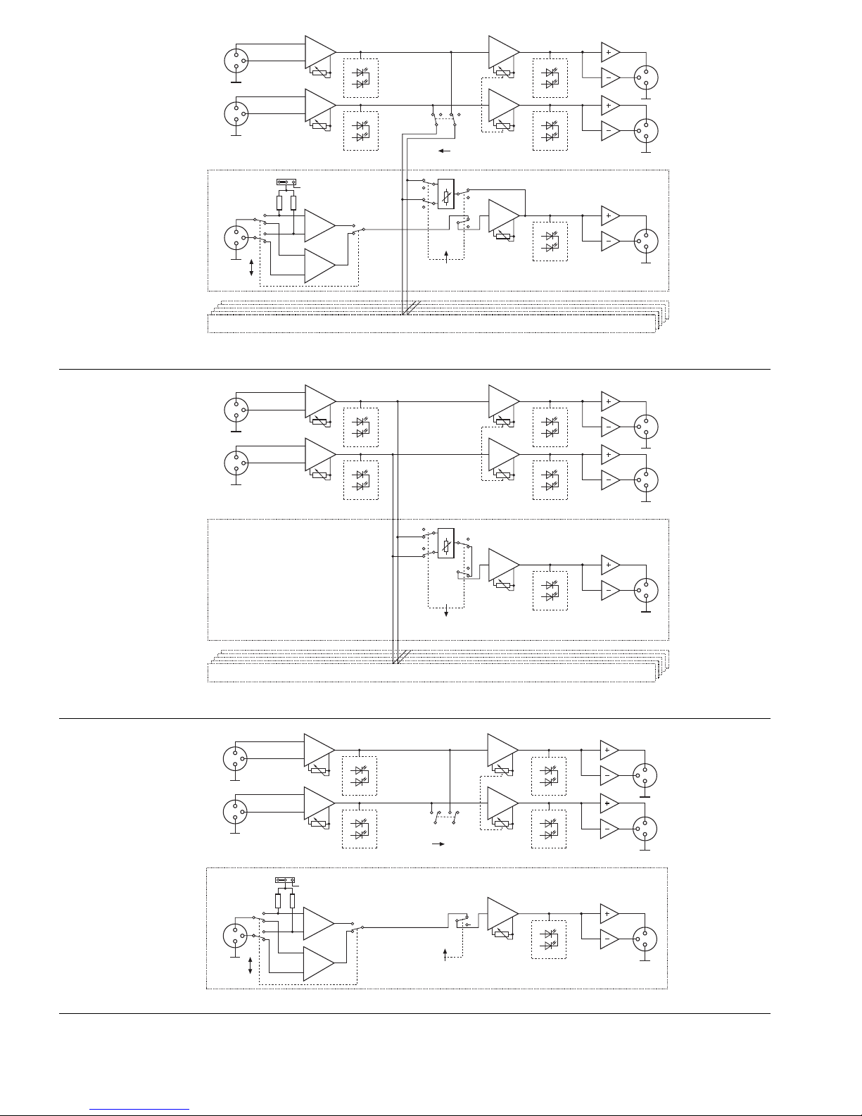
6.1 Mode de fonctionnement Mixeur (schéma 4)
Avec ce mode de fonctionnement, un canal stéréo
et six canaux mono au plus peuvent être mixés sur
un canal de sortie stéréo.
1) Enclenchez la touche de commutation MIX/
SPLIT (7) pour le canal correspondant et enclen-
chez la touche de commutation MIXER ON (8).
2) Tournez le réglage LEVEL STEREO OUT (9) jus-
qu’à ce que le rapport de mixage des sources
reliées soit réglé de manière optimale.
3) Avec les touches de commutation LINE/MIC (4),
réglez les canaux mono CH1–CH6 sur les sour-
ces reliées. Si un microphone est connecté,
enclenchez la touche de commutation et désen-
clenchez-la pour des appareils avec niveau ligne.
4) Avec les potentiomètres de réglage LEVEL STE-
REO IN (3) et les réglages de canaux CH1–CH6
(5), réglez le rapport de volume souhaité : réglez
les sources audio qui doivent être le plus fort de
sorte que la LED correspondante (1) brille briève-
ment en rouge pour un passage de musique
avec le volume le plus élevé.
5) Placez le signal de canal mono comme souhaité
dans la base stéréo avec les réglages PAN (6)
des canaux mono CH1–CH6.
6) Avec le réglage LEVEL STEREO OUT(9), réglez
le niveau définitif du signal master stéréo.
6.2 Mode de fonctionnement Répartiteur
(schéma 5)
Avec le mode de fonctionnement Répartiteur, un
signal stéréo peut être réparti sur six canaux mono
et un canal stéréo. Dans le cas de canaux mono, les
parts de signal du signal stéréo peuvent être réglées
séparément avec les réglages PAN. Pour un canal
de sortie stéréo, aucune attribution libre n’est possi-
ble, le signal d’entrée gauche est attribué au signal
de sortie gauche et le signal d’entrée droit est attri-
bué au signal de sortie droit.
1) Désenclenchez la touche de commutation MIX/
SPLIT (7) pour le canal correspondant.
2) Avec les réglages INPUT LEVEL (3), réglez le
niveau d’entrée du signal stéréo de telle sorte
que les LEDs (1) brillent brièvement en rouge
pour les passages de musique les plus forts.
3) Pour les six canaux mono, réglez la part voulue
du signal stéréo avec les réglages PAN (6).
4) Avec les réglages LEVEL CH1–CH6 (5), réglez
individuellement les niveaux des canaux mono.
5) Avec les réglages LEVEL STEREO OUT (9),
réglez le niveau du signal de sortie stéréo.
6.3 Mode de fonctionnement amplificateur
8canaux (schéma 6)
Avec ce mode de fonctionnement, les canaux fonc-
tionnent comme amplificateurs indépendants déli-
vrant un signal de sortie symétrique basse impé-
dance. Les niveaux des six canaux mono et du canal
stéréo peuvent être adaptés séparément. L’adapta-
tion de niveau est par exemple nécessaire si le
niveau de sortie d’une source de signal est trop faible
pour contrôler un appareil placé après. Avec ce
mode de fonctionnement, l’appareil peut également
être utilisé comme préamplificateur micro 6 voies.
1) Enclenchez la touche de commutation MIX/SPLIT
(7) pour le canal correspondant et desenclenchez
la touche de commutation MIXER ON (8).
2) Avec les touches de commutation LINE/MIC (4),
réglez les canaux mono CH1–CH6 sur les sour-
ces reliées. Si un microphone est relié, enclen-
chez la touche de commutation et pour des
appareils à niveau ligne, désenclenchez-la.
3) Pour des canaux mono, réglez le volume sou-
haité avec les réglages LEVEL CH1–CH6 (5).
4) Pour un canal stéréo, réglez le réglage LEVEL
STEREO OUT (9) sur le maximum.
5) Avec les réglages LEVEL STEREO IN (3), réglez
individuellement le niveau souhaité pour le canal
droit et le canal gauche.
6.4 Modes de fonctionnement combinés
Si en mode répartiteur, les six canaux mono ne sont
pas utilisés comme sorties, les canaux restants peu-
vent fonctionner comme amplificateurs distincts in-
dépendants. Voir chapitre 6.3.
7Caractéristiques techniques
Entrées
(Sensibilité d’entrée pour niveau de sortie 1V,
impédance d’entrée)
STEREO IN : . . . . . . . . . 250mV, 30kΩ,
XLR, symétrique
CH1–CH6 : . . . . . . . . . . Ligne 100mV, 40kΩ
commutable sur
Mic 1mV, 6,6kΩ
XLR, symétrique
Alimentation fantôme : . . 12V (commutable en
interne)
Sorties
(Niveau nominal, impédance de sortie)
STEREO OUT : . . . . . . . 1V, 200Ω
XLR, symétrique
CH1–CH6 : . . . . . . . . . . 1V, 200Ω
XLR, symétrique
Bande passante : . . . . . . . . 10Hz–30 000Hz,
(+0/
-
0,5dB)
Taux de distorsion : . . . . . . 0,02%
Rapport signal/bruit : . . . . . 81dB, pondéré
Diaphonie : . . . . . . . . . . . . .
-
63dB (1kHz)
Alimentation : . . . . . . . . . . . 230V~/50Hz/10VA
Température fonc. : . . . . . . 0–40°C
Dimensions (LxHxP) : . . . 482 x 48 x 205 mm,
1unité
Poids : . . . . . . . . . . . . . . . . 2,9kg
Tout droit de modification réservé.
6.1 Modalità mixer (fig. 4)
Nella modalità mixer, un canale stereo e fino a sei
canali mono possono essere miscelati su un canale
stereo d’uscita.
1) Premere fino allo scatto il selettore MIX/SPLIT
(7) per il relativo canale nonché il selettore
MIXER ON (8).
2) Aprire il regolatore LEVEL STEREO OUT (9) al
punto tale che si possa impostare in modo otti-
male il rapporto di miscelazione fra le sorgenti
collegate.
3) Con i commutatori LINE/MIC (4) adattare i canali
mono CH1–CH6 alle sorgenti collegate. Se è
collegato un microfono, premere il tasto fino allo
scatto; nel caso di apparecchi con livello Line
sbloccare il tasto.
4) Con i regolatori LEVEL STEREO IN (3) e con sei
quelli dei canali LEVEL CH1–CH6 (5) impo-
stare il suono desiderato: regolare le sorgenti che
devono essere le più forti in modo tale che il rela-
tivo LED (1) si accende brevemente di color
rosso nei passaggi musicali più forti.
5) Con i regolatori PAN (6) dei canali mono CH1–
CH6 posizionare il segnale mono nella base ste-
reo secondo il proprio gusto.
6) Con il regolatore LEVEL STEREO OUT (9) impo-
stare il livello definitivo del segnale stereo master.
6.2 Modalità splitter (fig. 5)
Nella modalità splitter, un segnale stereo può essere
distribuito fra sei canali mono e un canale stereo. Per
i canali mono, le parti del segnale stereo possono
essere impostate individualmente con l’aiuto del
regolatore panoramico. Nel canale stereo d’uscita
non è possibile un’assegnazione libera: il segnale di
sinistra è assegnato al canale sinistro d’uscita e il
segnale destro d’ingresso al segnale destro d’uscita.
1) Sbloccare il selettore MIX/SPLIT (7) per il rela-
tivo canale.
2) Con i regolatori INPUT LEVEL (3) impostare il
livello d’ingresso del segnale stereo in modo tale
che i LED (1) si accendono brevemente di rosso
nei brani musicali più forti.
3) Per i sei canali mono impostare la parte deside-
rata del segnale stereo servendosi dei regolatori
PAN (6).
4) Con i regolatori LEVEL CH1–CH 6 (5) impostare
il livello per ogni canale mono.
5) Con i regolatori LEVEL STEREO OUT (9) impos-
tare il livello del segnale stereo d’uscita.
6.3 Modalità amplificatore a 8 canali (fig. 6)
In questo modalità, i canali funzionano come ampli-
ficatori indipendenti che forniscono un segnale d’u-
scita simmetrico, a bassa impedenza. I livelli dei
canali mono e del canale stereo possono essere
adattati singolarmente. L’adattamento del livello è
necessario, p.es., se una sorgente presenta un
livello d’uscita troppo basso per poter pilotare un
apparecchio a valle. In questa modalità, l’appa-
recchio può essere impiegato anche come pream-
plificatore 6x per microfono.
1) Premere fino allo scatto il selettore MIX/SPLIT
(7) per il relativo canale e sbloccare il selettore
MIXER ON (8).
2) Con i commutatori LINE/MIC (4) adattare i canali
mono CH1–CH6 alle sorgenti collegate. Se è
collegato un microfono, premere il tasto fino allo
scatto; nel caso di apparecchi con livello Line
sbloccare il tasto.
3) Nei canali mono impostare il livello desiderato
con il regolatori LEVEL CH1–CH6 (5).
4) Nel canale stereo portare il regolatore LEVEL
STEREO OUT (9) sul massimo.
5) Con i regolatori LEVEL STEREO IN (3) impos-
tare il livello desiderato per il canale sinistro e per
il canale destro.
6.4 Modalità combinate
Se nella modalità splitter non si usano tutti e sei i
canali come uscite, gli altri canali possono funzio-
nare come amplificatori singoli, indipendenti. Vedi
cap. 6.3.
7Dati tecnici
Ingressi
(sensibilità all’ingresso con 1V di livello
d’uscita, impedenza all’ingresso )
STEREO IN: . . . . . . . . . . 250mV, 30kΩ
XLR, simmetrico
CH1–CH6: . . . . . . . . . . Line 100mV, 40kΩ
commutabile a
Mic1mV, 6,6kΩ
XLR, simmetrico
Alimentazione phantom: . 12V (commutabile
internamente)
Uscite
(livello nominale,
impedenza all’uscita)
STEREO OUT: . . . . . . . . 1V, 200Ω
XLR, simmetrica
CH1–CH6: . . . . . . . . . . 1V, 200Ω
XLR, simmetrica
Gamma di frequenze: . . . . . 10Hz–30000Hz
(+0/
-
0,5dB)
Fattore di distorsione: . . . . . 0,02%
Rapporto S/R: . . . . . . . . . . 81dB, valutato
Diafonia: . . . . . . . . . . . . . . .
-
63dB (1kHz)
Alimentazione: . . . . . . . . . . 230V~/50Hz/10VA
Temperatura d’esercizio: . . 0–40°C
Dimensioni (l x h x p): . . . . . 482 x 48 x 205mm,
1 unità di altezza
Peso: . . . . . . . . . . . . . . . . . 2,9kg
Con riserva di modifiche tecniche.
10
I
F
B
CH

11
1
2
3SIG
PEAK
IN
LEVEL LEVEL
OUT
1
2
3
1
2
3
LEVEL LEVEL
+12 V PHANTOM
1
2
3
IN
MIX
PAN
LEVEL
CHANNEL 1
STEREO CHANNEL
MIX
OUT
L
R
R
MIC
LINE
MIC
LINE
ON
OFF ON
SIG
PEAK
SIG
PEAK
SIG
PEAK
1
2
3L
1
2
3
SIG
PEAK
CHANNEL 2
-
6
➃
1
2
3SIG
PEAK
IN
LEVEL LEVEL
OUT
1
2
3
1
2
3
LEVEL LEVEL
PAN
LEVEL
CHANNEL 1
STEREO CHANNEL
OUT
L
R
R
SPLIT
SIG
PEAK
SIG
PEAK
SIG
PEAK
1
2
3L
1
2
3
SIG
PEAK
CHANNEL 2
-
6
➄
1
2
3SIG
PEAK
IN
LEVEL LEVEL
OUT
1
2
3
1
2
3
LEVEL LEVEL
+12 V PHANTOM
1
2
3
IN
MIX LEVEL
CHANNEL 1
-
6
STEREO CHANNEL
OUT
L
R
R
MIC
LINE
MIC
LINE
MIX
OFF
OFF ON
SIG
PEAK
SIG
PEAK
SIG
PEAK
1
2
3L
1
2
3
SIG
PEAK
➅
mode de fonctionnement
Mixeur
Modalità mixer
mode de fonctionnement
Répartiteur
Modalità splitter
amplificateur 8 canaux
amplificatore a 8 canali
Notice d’utilisation protégée par le copyright de MONACOR ®INTERNATIONAL GmbH & Co. KG. Toute
reproduction même partielle à des fins commerciales est interdite.
La MONACOR®INTERNATIONAL GmbH & Co. KG si riserva ogni diritto di elaborazione in qualsiasi forma
delle presenti istruzioni per l’uso. La riproduzione–anche parziale–per propri scopi commerciali è vietata.

Abrir el presente libro página 3 de manera a
visualizar los elementos y las conexiones.
1Elementos y conexiones
1.1 Parte delantera (esquema 1)
1LEDs para el nivel de señal.
Verde = señal de entrada disponible.
Rojo = señal de entrada en sobrecarga.
2Testigo de funcionamiento.
3Potenciómetros LEVEL para de la preamplifica-
ción del canal izquierdo y del canal derecho.
4Tecla de conmutación, respectivamente para los
canales mono 1–6, para adaptar el rango de
reglaje para los potenciómetros de nivel (5) a la
fuente de señal conectada en cada caso:
Fuente conectada línea: desencaja la tecla (po-
sición “LINE”): los reglajes van de
-
∞a +20dB.
Micro conectado: encaje la tecla (posición
“MIC”): los reglajes van de
-
∞a +60dB.
5Potenciómetro de reglaje delantero LEVEL res-
pectivamente para los canales CH1 a CH6.
Modo de funcionamiento SPLIT: para regular el
nivel del canal de las salidas CH1 a CH6.
Modo de funcionamiento MIXER: para regular la
parte del canal correspondiente a la señal total
en la salida STEREO OUT (12); el nivel de señal
regulado está presente simultáneamente en la
salida correspondiente (13) del canal.
6Potenciómetro PAN trasero, respectivamente
para los canales CH1 a CH6.
Modo de funcionamiento SPLIT: para regular la
relación entre el canal izquierdo y derecho de la
señal de entrada estéreo a la salida correspon-
diente (13).
Modo de funcionamiento MIXER: reglaje para
colocar la señal de entrada mono en la base
estéreo de la señal de salida.
7Tecla de conmutación MIX/SPLIT, respectiva-
mente para los canales mono CH1 a CH6, para
seleccionar el modo de funcionamiento:
Tecla desencajada: modo de funcionamiento
MIX.
Tecla encajada: modo de funcionamiento SPLIT.
8Tecla de conmutación MIXER ON:
Tecla encajada: el funcionamiento Mezclador
está activado. Si los dos canales mono respec-
tivos CH1 a CH6 funcionan en modo mesa de
mezcla, su nivel de canal se aplica en el canal
master “STEREO OUT”.
Tecla desencajada: el funcionamiento Mezclador
está desactivado. Si los canales mono respec-
tivos CH1 a CH6 están conmutados en “MIX”,
funcionan como amplificadores distintos.
9Potenciómetro LEVEL STEREO OUT para regu-
lar el nivel de las salidas STEREO OUT (12).
10 Interruptor POWER Marcha/Paro.
1.2 Parte trasera (esquema 2)
11 Cable de conexión para enchufar al 230V~/
50Hz.
12 Salida estéreo (2 x XLR, simétrico).
13 Salida mono de los canales CH1 a CH6 (XLR,
simétrico).
14 Entrada mono de los canales CH1 a CH6 (XLR,
simétrico).
15 Entrada estéreo (2 x XLR, simétrico).
2Consejos de utilización y seguridad
El aparato cumple con la normativa europea
89/336/CEE relacionada con la compatibilidad
electromagnética y con la normativa relacionada
con los aparatos de baja tensión 73/23/CEE.
Respecte escrupulosamente los puntos siguientes:
●El aparato está fabricado sólo para una utilización
en interior. Protéjalo de salpicaduras, de todo tipo
de proyecciones de agua, de una humedad ele-
vada y del calor (temperatura admisible
0–40°C).
●No deposite en ningún caso objetos que contie-
nen líquidos sobre el aparato.
●No haga funcionar nunca el aparato y desconéc-
telo inmediatamente en los casos siguientes:
1. El aparato o el cable de conexión presentan
daños visibles.
2. Después de una caída o accidente similar, si
tiene dudas sobre el estado del aparato.
3. Aparecen disfunciones.
En todos los casos, los daños deben repararse
por un técnico especializado.
●No desconecte nunca el aparato tirando del cable
directamente, sujete siempre el cable por la extre-
midad.
●Todo cable dañado debe cambiarse únicamente
por el fabricante o un técnico habilitado.
●Para la limpieza utilice siempre un trapo seco y
suave, no utilice nunca productos químicos o
agua.
●Declinamos toda responsabilidad en caso de
daños caporales o materiales resultandos de una
utilización no adecuada a las permitidas por el
aparato o el fabricante, si no está correctamente
conectado, utilizado o reparado por una persona
calificada y especializada; por estos mismos moti-
vos carecería de todo tipo de garantía.
Cuando el aparato está definidamente
sacado del servicio, deposítelo en una
fábrica de reciclaje de proximidad para
contribuir a una eliminación no contami-
nante.
¡Atención! El aparato esta alimentado por una
tensión peligrosa de 230V~. No haga nunca modi-
ficaciones al aparato que no están descritas en
este manual; en caso de mala manipulación podría
sufrir una descarga eléctrica.
Prosimy o otworzenie instrukcji na stronie 3,
gdzie znajdą Państwo opisywane elementy
sterujące i gniazda połączeniowe.
1Elementy użytkowe i gniazda
podłączeniowe
1.1 Panel przedni (rys. 1)
1Wskaźniki poziomu sygnału.
zielony = odpowiedni poziom sygnału
czerwony = przesterowanie
2Wskaźnik zasilania.
3Regulatory wzmocnienia wejściowego dla
kanałów lewego i prawego.
4Selektor czułości wejściowej (mikrofonowa,
liniowa) dla kanałów wejściowych 1 do 6, oraz
zakresu regulacji głośności za pomocą regula-
tora (5).
Aby wybrać źródło liniowe należy wycisnąć
przycisk (pozycja “LINE”):
Zakres regulacji wynosi
-
∞do +20dB
Aby wybrać źródło mikrofonowe należy wcisnąć
przycisk (pozycja “MIC”):
Zakres regulacji wynosi
-
∞do +60 dB
5Przednia gałka: regulator dla każdego z
kanałów CH1 do CH6.
Tryb splittera SPLIT: ustawianie poziomów
sygnałów wyjściowych dla kanałów CH1 do
CH6.
Tryb miksera MIXER: ustawianie poziomu
sygnału kanałowego w całościowym zmikso-
wanym sygnale na wyjściach STEREO OUT
(12); taki sam ustawiony poziom sygnału
całościowego jest również obecny na wyjściach
każdego z kanałów (13).
6Tylnia gałka PAN: regulator dla każdego z
kanałów CH1 do CH6.
Tryb splittera SPLIT: ustawianie stosunku
pomiędzy prawym a lewym kanałem sygnału
wejściowego stereofonicznego dla każdego z
wyjść (13).
Tryb miksera MIXER: regulacja usytuowania
sygnału mono w bazie stereo dla sygnału
wyjściowego.
7Selektor trybu pracy dla każdego z kanałów
CH1 do CH6:
Przycisk wyciśnięty: tryb miksera MIX
Przycisk wciśnięty: tryb splittera SPLIT
8Selektor MIXER ON:
Przycisk wciśnięty: włączony tryb miksowania.
Jeśli dane kanały CH1 do CH6 pracują w trybie
miksera ich sygnały są podawane na wyjście
kanału “STEREO OUT”.
Przycisk wyciśnięty: wyłączony tryb miksowa-
nia. Jeśli dane kanały CH1 do CH6 pracują w
trybie miksera (MIX), pracują one jako od-
dzielne wzmacniacze.
9Regulator STEREO OUT poziomu sygnału
wyjściowego na gniazdach STREO OUT (12).
10 Włącznik zasilania.
1.2 Panel tylni (rys. 2)
11 Kabel sieciowy do podłączenia gniazdka
(230 V~/50 Hz).
12 Wyjścia stereo (2 x XLR, symetryczne).
13 Wyjście mono dla kanałów CH1 do CH6 (XLR,
symetryczne).
14 Wejście mono dla kanałów CH1 do CH6 (XLR,
symetryczne).
15 Wyjście stereo (2 x XLR, symetryczne).
2Środki ostrożności
Urządzenie jest zgodne z wymaganiami normy o
zgodności elektromagnetycznej 89/336/EEC oraz
normy dotyczącej urządzeń niskonapięciowych
73/23/EEC.
Należy bezwzględnie przestrzegać poniższych
zasad:
●Urządzenie przeznaczone jest do użytku tylko
wewnątrz pomieszczeń. Należy chronić je przed
zalaniem i wilgocią oraz wysoką temperaturą
(dopuszczalna temperatura otoczenia pracy to
0–40°C).
●Nie wolno stawiać na urządzeniu żadnych naczyń
wypełnionych cieczami, np.: szklanek z napo-
jami.
●Nie wolno używać oraz należy natychmiast
odłączyć urządzenie od zasilania:
1. Jeżeli widoczne są jakiekolwiek uszkodzenia
urządzenia lub kabla zasilającego,
2. Jeżeli urządzenie upadło lub uległo podo-
bnemu wypadkowi, który mógł spowodować
jego uszkodzenie,
3. Jeśli urządzenie działa nieprawidłowo.
W każdym z powyższych przypadków urządzenie
musi zostać poddane naprawie przez odpowie-
dnio wyszkolony personel.
●Nie wolno odłączać urządzenia z gniazda siecio-
wego ciągnąc za kabel zasilający, należy zawsze
chwytać za wtyczkę.
●Uszkodzony kabel sieciowy może być wymie-
niony jedynie przez producenta lub przeszkolony
personel.
Uwaga! Urządzenie jest zasilane niebezpiecznym
dla życia napięciem zmiennym 230 V. Jego
naprawą powinien zajmować się tylko przeszko-
lony personel. Nie wolno dokonywać żadnych
modyfikacji nie opisanych w tej instrukcji. Samo-
dzielne manipulowanie może spowodować po-
rażenie prądem elektrycznym.
12
PL
E

3Posibilidades de utilización
El mezclador línea micro/repartidor línea se utiliza
para múltiples aplicaciones audio mediante su con-
cepto. En modo Repartidor, una señal de entrada
estéreo puede repartirse en respectivamente 6 sali-
das mono donde la parte de señal de la señal
estéreo es regulable individualmente para cada
canal vía reglajes de panorámico. En modo mesa
de mezcla, una señal estéreo y como mucho 6
señales mono con nivel micro o nivel línea pueden
mezclarse en una salida estéreo. Los 6 canales
mono y el canal estéreo pueden utilizarse también
como amplificadores distintos para una adaptación
de nivel o de impedancia.
4Posibilidades de instalación
El aparato está previsto para un montaje en rack
(482mm/19"), también puede instalarse libremente
sobre mesa. Para un montaje en rack, una unidad
(1U = 44,45mm) es necesaria.
5Conexiones
Antes de efectuar nuevas conexiones o cambiar
modificaciones existentes, apague el mezclador de
micro línea/Repartidor línea y los aparatos que
deben conectarse.
1) Conecte un aparato estéreo con nivel línea (por
ejemplo lector CD, mesa de mezcla…) a la
tomas XLR STEREO IN (15).
2) Es posible conectar a las entradas de los canales
mono CH1 a CH6 (14) micros pero también apa-
ratos mono con nivel línea.
3) Los amplificadores para altavoces o los aparatos
siguientes con nivel línea pueden conectarse
según su configuración, a las tomas XLR
CH1–CH6 OUT (13) y STEREO OUT (12).
5.1 Activación de la alimentacion phantom
Para poder hacer funcionar también micros a ali-
mentacion phantom, puede activar una alimenta-
cion phantom de 12V separadamente para cada
uno de los 6 canales mono.
1) Desenchufe la toma de la red.
2) Desatornille la tapa de la caja.
3) Para los canales elegidos, coloque las grapas
correspondientes JP101 (para canal CH1) a
JP601 (para canal CH6) de “OFF” hacia “ON”.
4) Atornille la caja.
5) Le aconsejamos de señalar las tomas de entrada
de los canales con la alimentación phantom en
función.
6Utilización
1) Antes de conectar, los potenciómetros de reglaje
(5 y 9) póngalos en la posición mínima para evi-
tar todo ruido fuerte durante la conexión.
2) Conecte el aparato con el interruptor POWER
(10). El LED rojo (2) encima del interruptor brilla
como testigo de funcionamiento. Después
conecte los aparatos.
¡Atención! Para conectar la alimentacion phan-
tom, el aparato debe de estar abierto. Sólo un per-
sonal calificado está autorizado a efectuar esta
manipulación.
¡Atención! Si la alimentacion phantom está encen-
dida, no conecte ningún micro asimétrico o apara-
tos con nivel línea a la entrada correspondiente.
Estos micros o estos aparatos pueden dañarse.
●Do czyszczenia obudowy należy używać tylko
suchej, miękkiej ściereczki. Nie wolno używać
wody lub innych środków chemicznych.
●Dostawca oraz producent nie ponoszą odpo-
wiedzialności za ewentualnie wynikłe szkody
materialne lub uszczerbki na zdrowiu, jeśli urzą-
dzenie było używane niezgodnie z przeznacze-
niem, zostało niepoprawnie zainstalowane lub
obsługiwane oraz było poddawane naprawom
przez nieautoryzowany personel.
3Zastosowanie
Zgodnie z koncepcją, urządzenie to ma wiele
zastosowań. W trybie splittera może służyć do roz-
dzielenia sygnału stereofonicznego na sześć kana-
łów mono, gdzie w każdym kanale część sygnału
stereo może być regulowana indywidualnie za
pomocą regulatora panoramy. W trybie miksera
sygnał stereo oraz maksymalnie sześć sygnałów
mono (o poziomie mikrofonowym lub liniowym)
może być zmiksowanych w jeden kanał stereofo-
niczny. Urządzenie może także być użyte jako 8
niezależnych przedwzmacniaczy (6 kanałów mono
oraz 1 stereo) służących do odpowiedniego dopa-
sowania poziomu wyjściowego lub impedancji.
4Montaż
Urządzenie jest przeznaczone do montażu racko-
wego (482 mm/19") ale można je także ustawić
według potrzeb na półce. W półce rackowej wyma-
gana jest przestrzeń 1 U = 44,5 mm.
5Podłączanie urządzenia
Przed podłączaniem nowych urządzeń lub zmianą
istniejących należy wyłączyć LMS-808 oraz
współpracujące z nim urządzenia.
1) Podłączyć liniowe urządzenie stereofoniczne
(np. odtwarzacz CD, mikser, itd.) do gniazd
STEREO IN (15) typu XLR.
2) Do gniazd mono kanałów CH1 do CH6 (14)
można podłączyć zarówno mikrofony jak i
monofoniczne urządzenia liniowe (z wyjściem o
poziomie liniowym).
3) Do wyjść CH1 do CH6 (13) oraz STEREO OUT
(12) typu XLR można w zależności od potrzeb
podłączyć wzmacniacze mocy lub aktywne
zestawy głośnikowe.
5.1 Włączanie zasilania phantomowego
LMS-808 daje możliwość włączenia zasilania
phantomowego 12 V potrzebnego dla pracy nie-
których mikrofonów niezależnie dla każdego z
sześciu kanałów.
1) Odłączyć wtyczkę zasilającą z gniazdka siecio-
wego.
2) Odkręcić pokrywę obudowy urządzenia.
3) Dla danego kanału przestawić odpowiednią
zworkę JP101 (dla kanału CH1) do JP601 (dla
kanału CH6) z pozycji “OFF” na “ON”.
4) Założyć pokrywę i przykręcić ją z powrotem.
5) Zaleca się oznaczyć kanał dla którego włączono
zasilanie phantomowe!
6Obsługa
1) Aby uniknąć stuku przy włączeniu zaleca się
wszystkie regulatory wyjściowe (5 oraz 9)
skręcić na minimum.
2) Włączyć urządzenie włącznikiem POWER (10).
Zapali się wskaźnik nad przełącznikiem (2).
Następnie należy włączyć podłączone urządze-
nia.
Uwaga! Aby włączyć zasilanie phantomowe należy
otworzyć obudowę urządzenia. Dlatego też należy
to zostawić wykwalifikowanemu personelowi.
Uwaga! Jeśli na danym kanale jest włączone
zasilanie phantomowe nie wolno do niego
podłączać niezbalansowanych mikrofonów lub
urządzeń liniowych. W przeciwnym przypadku
zostaną one uszkodzone.
Jeśli urządzenie nie będzie już nigdy
więcej używane, wskazane jest przeka-
zanie go do miejsca utylizacji odpadów,
aby zostało zniszczone bez szkody dla
środowiska.
13
PL
E

6.1 Tryb miksera (rys. 4)
W trybie miksera kanał stereofoniczny oraz wszy-
stkie sześć kanałów monofonicznych mogą zostać
zmiksowane do jednego kanału wyjściowego ste-
reofonicznego.
1) Włączyć dla wybranego kanału przycisk MIX/
SPLIT (7) oraz przycisk MIXER ON (8).
2) Ustawić poziom miksowanego sygnału za
pomocą regulatora LEVEL STEREO OUT (9) tak,
aby można było dokonywać dalszych ustawień
dla podłączonych sygnałów.
3) Za pomocą przełącznika LINE/MIC (4) wybrać
typ źródła audio podłączonego do kanałów
CH 1 do CH 6: dla mikrofonu wcisnąć przycisk,
dla źródła liniowego wycisnąć.
4) Za pomocą regulatorów LEVEL STEREO IN (3)
oraz LEVEL dla kanałów CH1 do CH6 (5) usta-
wić odpowiedni stosunek głośności: regulatory
dla kanałów które mają być najgłośniejsze
powinny być tak ustawione aby przy szczyto-
wych poziomach zapalały się wskaźniki LED (1).
5) Za pomocą regulatorów panoramy PAN (6) dla
kanałów CH1 do CH6 ustawić położenie sy-
gnałów mono w bazie stereo.
6) Za pomocą regulatora LEVEL STEREO OUT (9)
ustawić ostateczny poziom zmiksowanego
sygnału.
6.2 Tryb splittera (rys. 5)
W trybie splittera sygnał stereofoniczny może być
rozdzielony na sześć kanałów mono oraz kanał ste-
reofoniczny. Dla kanałów mono wybór części
sygnału stereofonicznego można dokonać za po-
mocą regulatora PAN. W przypadku wyjścia stereo
nie ma wyboru: kanał lewy sygnału wejściowego
jest przyporządkowany kanałowi lewemu sygnału
wyjściowego natomiast kanał prawy kanałowi pra-
wemu.
1) Wycisnąć przycisk MIX/SPLIT (7) dla wybranych
kanałów.
2) Za pomocą regulatorów głośności INPUT LEVEL
(3) ustawić poziom wejściowy sygnału stereo
tak, aby szczytowych poziomach sygnału
zapalały się wskaźniki LED (1).
3) Dla kanałów mono ustawić za pomocą regula-
tora PAN (6) żądaną część sygnału stereo.
4) Za pomocą regulatorów LEVEL dla kanałów
CH 1 do CH 6 (5) ustawić w zależności od po-
trzeb poziom sygnału.
5) Regulatorem LEVEL STREO OUTPUT (9) usta-
wić poziom stereofonicznego sygnału wyjścio-
wego.
6.3 Tryb 8-kanałowy (rys. 6)
W tym trybie wszystkie kanały pracują niezależnie
jako wzmacniacze i dostarczają na wyjście zbalan-
sowany sygnał wyjściowy. Poziomy dla wszystkich
kanałów mogą być regulowane niezależnie. Taki
tryb można wykorzystać jeśli sygnał wyjściowy
źródła jest za niski dla kolejnego urządzenia w
torze sygnałowym. W tym trybie urządzenie może
pracować jako 6 kanałowy przedwzmacniacz
mikrofonowy.
1) Wcisnąć dla wybranego kanału przycisk MIX/
SPLIT (7) oraz wycisnąć przycisk MIXER ON (8).
2) Za pomocą przycisków LINE/MIC (4) wybrać
dla kanałów CH1 do CH2 typ podłączonego
źródła sygnału: dla mikrofonu wcisnąć przycisk,
dla źródła liniowego wycisnąć.
3) Za pomocą regulatorów LEVEL dla kanałów
CH 1 do CH 6 (5) ustawić w zależności od po-
trzeb poziom sygnału.
4) Dla kanału stereofonicznego regulator głoś-
ności LEVEL STEREO OUTPUT (9) ustawić na
maksimum.
5) Ustawić za pomocą regulatorów LEVEL STEREO
IN (3) niezależnie dla prawego i lewego kanału
poziom głośności.
6.4 Tryb kombinowany
Jeśli nie wszystkie sześć kanałów mono są wyma-
gane jako wyjścia w trybie splittera, pozostałe
można wykorzystać jako niezależne przedwzma-
cniacze: zob. rozdział 6.3.
7Dane techniczne
Wejścia
(Czułość wejściowa przy poziomie wyjściowym 1 V,
impedancja wejściowa)
STEREO IN: . . . . . . . . . . . 250 mV, 30 kΩ,
XLR, zbalansowane
CH1 do CH6: . . . . . . . . . . Line 100 mV, 40 kΩ
przełączane na
Mic 1 mV, 6,6 kΩ,
XLR, zbalansowane
Zasilanie phantomowe: . . 12 V (włączane
wewnętrznie)
Wyjścia
(poziom znamionowy, impedancja wyjściowa)
STEREO OUT: . . . . . . . . . 1 V, 200 Ω,
XLR, zbalansowane
CH1 do CH6: . . . . . . . . . . 1 V, 200 Ω,
XLR, zbalansowane
Pasmo przenoszenia: . . . . . 10 Hz – 30 000 Hz
(+0/
-
0,5dB)
THD: . . . . . . . . . . . . . . . . . . . 0,02 %
Stosunek S/N: . . . . . . . . . . . 81 dB/ważony
Przesłuch międzykanałowy:
-
63 dB (1 kHz)
Zasilanie: . . . . . . . . . . . . . . . 230 V~/50 Hz/10 VA
Temperatura pracy: . . . . . . . 0 –40 °C
Wymiary (S x W x G): . . . . . . 482 x 48 x 205 mm,
1U
Waga: . . . . . . . . . . . . . . . . . . 2,9 kg
Z zastrzeżeniem do możliwych zmian.
14
PL
E6.1 Modo de funcionamiento Mezclador
(esquema 4)
Con este modo de funcionamiento, un canal estéreo
y 6 canales mono como mucho pueden mezclarse a
un canal de salida estéreo.
1) Encaje la tecla de conmutación MIX/SPLIT (7)
para el canal correspondiente y la tecla de con-
mutación MIXER ON (8).
2) Gire el potenciómetro LEVEL STEREO OUT (9)
hasta que la relación de mezcla de las fuentes
conectadas se regulen de manera óptima.
3) Con las teclas de conmutación LINE/MIC (4),
regule los canales mono CH1–CH6 a las fuen-
tes conectadas. Si un micro está conectado,
encaje la tecla de conmutación y desencájela
para los aparatos con nivel línea.
4) Con los potenciómetros LEVEL STEREO IN (3) y
los reglajes de canales CH1–CH6 (5), regule la
relación del volumen deseado: regule las fuentes
audio que deben estar más fuertes de manera a
que el LED correspondiente (1) brille brevemente
en rojo para una continuidad de música con un
volumen lo más elevado.
5) Coloque la señal del canal mono como deseado
en la base estéreo con los potenciómetros PAN
(6) de los canales mono CH1–CH6.
6) Con el potenciómetro LEVEL STEREO OUT (9),
regule el nivel definitivo de la señal master estéreo.
6.2 Modo de funcionamiento Repartidor
(esquema 5)
Con el modo de funcionamiento Repartidor, puede
repartir una señal estéreo en 6 canales mono y 1
canal estéreo. En el caso de canales mono, las par-
tes de señal estéreo pueden regularse separada-
mente con los potenciómetros PAN. Para un canal
de salida estéreo, ninguna atribución libre es posi-
ble, la señal de entrada izquierda se atribuye a la
señal de salida izquierda y la señal de entrada
derecha se atribuye a la señal de salida derecha.
1) Desencaje la tecla de conmutación MIX/SPLIT
(7) para el canal correspondiente.
2) Con los potenciómetros INPUT LEVEL (3),
regule el nivel de entrada de señal estéreo de
manera que los LEDs (1) brillen brevemente en
rojo para las canciones con volumen más fuerte.
3) Para los 6 canales mono, regule la parte del volu-
men de la señal estéreo con los potenciómetros
PAN (6).
4) Con los potenciómetros LEVEL CH1–CH6 (5),
regule individualmente los niveles de los canales
mono.
5) Con los potenciómetros LEVEL STEREO OUT
(9), regule el nivel de la señal de salida estéreo.
6.3 Modo de funcionamiento amplificador
8canales (esquema 6)
Con este modo de funcionamiento, los canales fun-
cionan como amplificadores independientes libe-
rando una señal de salida simétrica de baja impe-
dancia. Los niveles de los 6 canales mono y del
canal estéreo pueden adaptarse separadamente.
La adaptación del nivel es por ejemplo necesaria si
el nivel de salida de una fuente de señal es
demasiada baja para controlar un aparato colocado
después. Con este modo de funcionamiento, el apa-
rato también puede utilizarse como preamplificador
micro 6 vías.
1) Encaje la tecla de conmutación MIX/SPLIT (7)
para el canal correspondiente y desencaje la
tecla de conmutación MIXER ON (8).
2) Con las teclas de conmutación LINE/MIC (4),
regule los canales mono CH1 –CH6 en las fuen-
tes conectadas. Si un micro está conectado,
encaje la tecla de conmutación y para los apara-
tos a nivel línea, desencájela.
3) Para los canales mono, regule el volumen
deseado con los potenciómetros LEVEL
CH1–CH6 (5).
4) Para un canal estéreo, regule el potenciómetro
LEVEL STEREO OUT (9) en el máximo.
5) Con los potenciómetros LEVEL STEREO IN (3),
regule individualmente el nivel deseado para el
canal derecho y el canal izquierdo.
6.4 Modos de funcionamiento combinados
Si en modo repartidor, los 6 canales mono no se uti-
lizan como salidas, los canales restantes pueden
funcionar como amplificadores distintos e indepen-
dientes. Vea capítulo 6.3.
7Características técnicas
Entradas
(Sensibilidad de entrada para el nivel de salida 1V,
impedancia de entrada).
STEREO IN: . . . . . . . . . . 250mV, 30kΩ,
XLR, simétrica
CH1–CH6: . . . . . . . . . . Línea 100mV, 40kΩ
conmutable en
Mic 1mV, 6,6kΩ
XLR, simétrica
Alimentacion phantom: . . . . 12V (conmutable en
interno).
Salidas (Nivel nominal, impedancia de salida)
STEREO OUT: . . . . . . . . 1V, 200Ω
XLR, simétrica
CH1–CH6: . . . . . . . . . . 1V, 200Ω
XLR, simétrica.
Banda pasante: . . . . . . . . . 10Hz–30000Hz,
(+0/
-
0,5dB)
Tasa de distorsión: . . . . . . . 0,02%
Relación señal/ruido: . . . . . 81dB, ponderada
Separación de canales: . . . 63dB (1kHz)
Alimentación: . . . . . . . . . . . 230V~/50Hz/10VA
Temperatura func. . . . . . . . 0–40°C
Dimensiones (LxAxP): ... 482 x 48 x 205mm,
1unidad de altura
Peso: . . . . . . . . . . . . . . . . . 2,9kg.
Nos reservamos el derecho de modificación.

15
1
2
3SIG
PEAK
IN
LEVEL LEVEL
OUT
1
2
3
1
2
3
LEVEL LEVEL
+12 V PHANTOM
1
2
3
IN
MIX
PAN
LEVEL
CHANNEL 1
STEREO CHANNEL
MIX
OUT
L
R
R
MIC
LINE
MIC
LINE
ON
OFF ON
SIG
PEAK
SIG
PEAK
SIG
PEAK
1
2
3L
1
2
3
SIG
PEAK
CHANNEL 2
-
6
➃
1
2
3SIG
PEAK
IN
LEVEL LEVEL
OUT
1
2
3
1
2
3
LEVEL LEVEL
PAN
LEVEL
CHANNEL 1
STEREO CHANNEL
OUT
L
R
R
SPLIT
SIG
PEAK
SIG
PEAK
SIG
PEAK
1
2
3L
1
2
3
SIG
PEAK
CHANNEL 2
-
6
➄
1
2
3SIG
PEAK
IN
LEVEL LEVEL
OUT
1
2
3
1
2
3
LEVEL LEVEL
+12 V PHANTOM
1
2
3
IN
MIX LEVEL
CHANNEL 1
-
6
STEREO CHANNEL
OUT
L
R
R
MIC
LINE
MIC
LINE
MIX
OFF
OFF ON
SIG
PEAK
SIG
PEAK
SIG
PEAK
1
2
3L
1
2
3
SIG
PEAK
➅
Modo de funcionamiento
Mesa de mezcla
Tryb miksera
Modo de funcionamiento
Repartidor
Tryb splittera
Amplificador 8 canales
Tryb 8-kanałowy
Instrukcje obsługi są chronione prawem copyright for MONACOR®INTERNATIONAL GmbH & Co. KG.
Przetwarzanie całości lub części instrukcji dla osobistych korzyści finansowych jest zabronione.
Manual de instrucciones protegido por el copyright de MONACOR®INTERNATIONAL GmbH & Co. KG.
Toda reproducción incluida parcial con fines comerciales está prohibida.

LMS-808
Lees aandachtig de onderstaande veiligheidsvoor-
schriften, alvorens het toestel in gebruik te nemen.
Mocht u bijkomende informatie over de bediening
van het toestel nodig hebben, lees dan de Engelse
tekst van deze handleiding.
Veiligheidsvoorschriften
Dit toestel is in overeenstemming met de EU-richtlijn
89/336/EEG voor elektromagnetische compatibili-
teit en 73/23/EEG voor toestellen op laagspanning.
Let eveneens op het volgende:
●Het apparaat is enkel geschikt voor gebruik bin-
nenshuis. Vermijd druip- en spatwater, uitzonder-
lijk warme plaatsen en plaatsen met een hoge
vochtigheid (toegestaan omgevingstemperatuur-
bereik: 0–40°C).
●Plaats geen bekers met vloeistof zoals drinkgla-
zen etc. op het apparaat.
●Schakel het apparaat niet in resp. trek onmiddel-
lijk de stekker uit het stopcontact:
1. wanneer het apparaat of het netsnoer zichtbaar
beschadigd is,
2. wanneer er een defect zou kunnen optreden
nadat het apparaat bijvoorbeeld is gevallen,
3. wanneer het apparaat slecht functioneert.
Het apparaat moet in elk geval hersteld worden
door een gekwalificeerd vakman.
●Trek de stekker nooit met het snoer uit het stop-
contact, maar met de stekker zelf.
●Een beschadigd netsnoer mag enkel door de
fabrikant of door een gekwalificeerd persoon her-
steld worden.
●Verwijder het stof met een droge, zachte doek.
Gebruik zeker geen water of chemicaliën.
●In geval van ongeoorloofd of verkeerd gebruik,
verkeerde aansluiting, foutieve bediening of van
herstelling door een niet-gekwalificeerd persoon
vervalt de garantie en de verantwoordelijkheid
voor hieruit resulterende materiële of lichamelijke
schade.
Wanneer het apparaat definitief uit
bedrijf wordt genomen, bezorg het dan
voor milieuvriendelijke verwerking aan
een plaatselijk recyclagebedrijf.
Let op! De netspanning (230V~) van het apparaat
is levensgevaarlijk. Open het toestel nooit op een
wijze die niet in deze handleiding is beschreven,
want door onzorgvuldige ingrepen loopt u het risico
van elektrische schokken.
LMS-808
Innan enheten tas i bruk, läs först igenom säkerhets-
föreskrifterna. Om ytterligare information önskas,
läs igenom den engelska texten som medföljer.
Säkerhetsföreskrifter
Enheten uppfyller EG-direktiv 89/336/EWG av-
seende elektromagnetiska störfält samt EG-direktiv
73/23/EWG avseende lågspänningsapplikationer.
Ge ovillkorligen även akt på följande:
●Enheten är endast avsedda för inomhusbruk.
Skydda enheten mot vätskor, hög luftfuktighet
och hög värme (tillåten omgivningstemperatur
0–40°C).
●Placera inte föremål innehållande vätskor, t.ex.
dricksglass, på enheten.
●Använd inte enheten och ta omedelbart kontakten
ur elurtaget om något av följande fel uppstår:
1. Enheten eller elsladden har synliga skador.
2. Enheten är skadad av fall e. d.
3. Enheten har andra felfunktioner.
Enheten skall alltid lagas på verkstad av utbildad
personal.
●Drag aldrig ut kontakten genom att dra i elsladden
utan ta tag i kontaktkroppen.
●En skadad elsladd skall endast bytas på verkstad
eller på tillverkaren.
●Rengör endast med en mjuk och torr trasa,
använd aldrig kemikalier eller vatten vid
rengöring.
●Om enheten används för andra ändamål än
avsett, om den kopplas in felaktigt, om den an-
vänds på fel sätt eller inte repareras av auktorise-
rad personal upphör alla garantier att gälla och
inget ansvar tas heller för uppkommen skada på
person eller materiel.
Om enheten skall kasseras bör de läm-
nas in till återvinning.
Varning! Enheten använder hög spänning internt
(230V~). Överlåt all service till utbildad personal
och gör inga egna ingrepp i enheten. All modifier-
ing skall göras i enlighet till beskrivningen i instruk-
tionsmanualen. Oaktsamhet kan leda till elskador.
16
S
LMS-808
Læs nedenstående sikkerhedsoplysninger opmærk-
somt igennem før ibrugtagning af enheden. Bortset
fra sikkerhedsoplysningerne henvises til den engel-
ske tekst.
Vigtige sikkerhedsoplysninger
Enheden overholder EU-direktivet 89/336/EØF ved-
rørende elektromagnetisk kompatibilitet og lavspæn-
dingsdirektivet 73/23/EØF.
Vær altid opmærksom på følgende:
●Enheden er kun beregnet til indendørs brug. Bes-
kyt den mod vanddråber og -stænk, høj luftfugtig-
hed og varme (tilladt omgivelsestemperatur
0–40°C).
●Undgå at placere væskefyldte genstande, som
f.eks. glas, ovenpå enheden.
●Tag ikke enheden i brug og tag straks stikket ud af
stikkontakten i følgende tilfælde:
1. hvis der er synlig skade på enheden eller net-
kablet,
2. hvis der kan være opstået skade, efter at enhe-
den er tabt eller lignende,
3. hvis der forekommer fejlfunktion.
Enheden skal altid repareres af autoriseret perso-
nel.
●Tag aldrig netstikket ud af stikkontakten ved at
trække i kablet, tag fat i selve stikket.
●Et beskadiget netkabel må kun repareres af pro-
ducenten eller af autoriseret personel.
●Til rengøring må kun benyttes en tør, blød klud;
der må under ingen omstændigheder benyttes
kemikalier eller vand.
●Hvis enheden benyttes til andre formål, end den
oprindeligt er beregnet til, hvis den ikke er tilsluttet
korrekt, hvis den betjenes forkert, eller hvis den
ikke repareres af autoriseret personel, omfattes
eventuelle skader ikke af garantien.
Hvis enheden skal tages ud af drift for
bestandigt, skal den bringes til en lokal
genbrugsstation for bortskaffelse.
Forsigtig! Enheden benytter livsfarlig netspæn-
ding (230 V~). Ved usagligt udførte reparationer
kan der opstå betydelig fare for brugeren. Enheden
skal altid repareres af autoriseret personel.
DK
B
NL

17
LMS-808
Ole hyvä ja huomioi aina seuraavat turvallisuutta
koskevat ohjeet ennen laitteen käyttöönottoa. Katso
käyttöön liittyviä ohjeita Englanninkielisistä ohjeista,
jos tarvitset lisää tietoa laitteen käytöstä.
Turvallisuudesta
Tämä laite vastaa direktiiviä 89/336/EEC sähkö-
magneettisesta yhteensopivuudesta sekä matala-
jännitedirektiiviä 73/23/EEC.
Huomioi seuraavat seikat:
●Tämä laite soveltuu käytettäväksi ainoastaan
sisätiloissa. Suojele laitetta kosteudelta, vedeltä
ja kuumuudelta (sallittu ympäröivä lämpötila
0–40Celsius astetta).
●Älä aseta laitteen päälle astioita, joissa on
nestettä, esimerkiksi juomalaseja.
●Irrota virtajohto pistorasiasta, äläkä käynnistä lai-
tetta, jos:
1. virtajohdossa on havaittu vaurio,
2. laitteiden putoaminen tai vastaava vahinko on
saattanut aiheuttaa vaurion,
3. laitteissa esiintyy toimintahäiriöitä.
Kaikissa tapauksissa laite tulee toimittaa valtuu-
tettuun huoltoliikkeeseen.
●Älä koskaan irrota virtajohtoa pistorasiasta joh-
dosta vetämällä.
●Vahingoittunut virtajohto tulee vaihdattaa valtuute-
tussa huoltoliikkeessä.
●Käytä puhdistamiseen pelkästään kuivaa, peh-
meää kangasta. Älä käytä puhdistusaineita taikka
vettä puhdistamiseen.
●Jos laitetta käytetään muuhun kuin mihin se on
instead ne ovat alun perin tarkoitettu, jos niitä
käytetään väärin taikka niitä ei ole huollettu tai
korjattu valtuutetussa huoltoliikkeessä, ei takuu
ole voimassa, eikä valmistaja, maahantuoja tai
myyjä ota vastuuta aiheutuneesta vahingosta.
Kun laite poistetaan lopullisesti käytöstä,
huolehdi, että laite hävitetään asianmu-
kaisesti jätteenkäsittelylaitoksessa.
Huomio! Tämä laite toimii vaarallisella 230V~ jän-
nitteellä. Huollon saa tehdä vain siihen koulutuk-
sen saanut henkilö. Laitteeseen ei saa tehdä ohje-
kirjan vastaisia muutoksia. Asiaa tuntematon
käsittely saattaa aiheuttaa sähköiskun.
FIN

Copyright©by MONACOR INTERNATIONAL GmbH & Co. KG, Bremen, Germany. All rights reserved. A-0335.99.01.01.2005
®
Table of contents
Other Stageline Music Mixer manuals

Stageline
Stageline MMX-3USB User manual

Stageline
Stageline MPX-30DMP User manual

Stageline
Stageline MPX-500 User manual

Stageline
Stageline MMX-22 User manual

Stageline
Stageline mpx-2008 User manual

Stageline
Stageline MPX-480 User manual

Stageline
Stageline PMX-64FX User manual

Stageline
Stageline MPX-430/BL User manual

Stageline
Stageline MPX-610 User manual