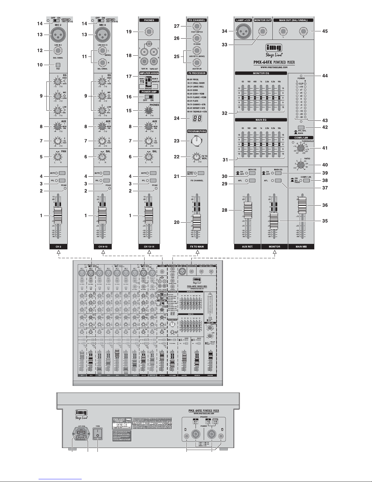
Stageline PMX-64FX User manual

PMX-64FX Bestellnummer 20.2880
BEDIENUNGSANLEITUNG • INSTRUCTION MANUAL • MODE D’EMPLOI
ISTRUZIONI PER L’USO • GEBRUIKSAANWIJZING • MANUAL DE INSTRUCCIONES • INSTRUKCJA OBSŁUGI
SIKKERHEDSOPLYSNINGER • SÄKERHETSFÖRESKRIFTER • TURVALLISUUDESTA
POWERED MIXER
TABLE DE MIXAGE AMPLIFIÉE
MIXER AMPLIFICATO

2
wwwwww..iimmggssttaaggeelliinnee..ccoomm
Bevor Sie einschalten …
Wir wünschen Ihnen viel Spaß mit Ihrem neuen Gerät
von „img Stage Line“. Bitte lesen Sie diese Bedienungs-
anleitung vor dem Betrieb gründlich durch. Nur so lernen
Sie alle Funktionsmöglichkeiten kennen, vermeiden
Fehlbedienungen und schützen sich und Ihr Gerät vor
eventuellen Schäden durch unsachgemäßen Gebrauch.
Heben Sie die Anleitung für ein späteres Nachlesen auf.
Der deutsche Text beginnt auf der Seite 4.
Before switching on …
We wish you much pleasure with your new “img Stage
Line” unit. Please read these operating instructions care-
fully prior to operating the unit. Thus, you will get to know
all functions of the unit, operating errors will be pre-
vented, and yourself and the unit will be protected
against any damage caused by improper use. Please
keep the operating instructions for later use.
The English text starts on page 10.
Avant toute installation …
Nous vous souhaitons beaucoup de plaisir à utiliser cet
appareil “img Stage Line”. Lisez ce mode dʼemploi entiè-
rement avant toute utilisation. Uniquement ainsi, vous
pourrez apprendre lʼensemble des possibilités de fonc-
tionnement de lʼappareil, éviter toute manipulation erronée
et vous protéger, ainsi que lʼappareil, de dommages éven-
tuels engendrés par une utilisation inadaptée. Conser-
vez la notice pour pouvoir vous y reporter ultérieurement.
La version française se trouve page 16.
Prima di accendere …
Vi auguriamo buon divertimento con il vostro nuovo
apparecchio di “img Stage Line”. Leggete attentamente
le istruzioni prima di mettere in funzione lʼapparecchio.
Solo così potete conoscere tutte le funzionalità, evitare
comandi sbagliati e proteggere voi stessi e lʼapparecchio
da eventuali danni in seguito ad un uso improprio. Con-
servate le istruzioni per poterle consultare anche in
futuro.
Il testo italiano inizia a pagina 22.
D
A
CH
GB
Antes de la utilización …
Le deseamos una buena utilización para su nuevo apa-
rato “img Stage Line”. Por favor, lea estas instrucciones
de uso atentamente antes de hacer funcionar el aparato.
De esta manera conocerá todas las funciones de la uni-
dad, se prevendrán errores de operación, usted y el apa-
rato estarán protegidos en contra de todo daño causado
por un uso inadecuado. Por favor, guarde las instruccio-
nes para una futura utilización.
La versión española comienza en la página 34.
Voor u inschakelt …
Wij wensen u veel plezier met uw nieuwe apparaat van
“img Stage Line”. Lees deze gebruikershandleiding gron-
dig door, alvorens het apparaat in gebruik te nemen.
Alleen zo leert u alle functies kennen, vermijdt u foutieve
bediening en behoedt u zichzelf en het apparaat voor
eventuele schade door ondeskundig gebruik. Bewaar de
handleiding voor latere raadpleging.
De Nederlandstalige tekst vindt u op pagina 28.
Przed uruchomieniem …
Życzymy zadowolenia z nowego produktu “img Stage
Line”. Dzięki tej instrukcji obsługi będą państwo w stanie
poznać wszystkie funkcje tego urządzenia. Stosując się
do instrukcji unikną państwo błędów i ewentualnego
uszkodzenia urządzenia na skutek nieprawidłowego
użytkowania. Prosimy zachować instrukcję.
Tekst polski zaczyna się na stronie 40.
Før du tænder …
Tillykke med dit nye “img Stage Line” produkt. Læs sik-
kerhedsanvisningerne nøje før ibrugtagning, for at
beskytte Dem og enheden mod skader, der skyldes for-
kert brug. Gem venligst denne betjeningsvejledning til
senere brug.
Sikkerhedsanvisningerne findes på side 46.
Innan du slår på enheten …
Vi önskar dig mycket glädje med din nya “img Stage
Line” produkt. Läs igenom säkerhetsföreskrifterna innan
enheten tas i bruk för att undvika skador till följd av
felaktig hantering. Behåll instruktionerna för framtida
bruk.
Säkerhetsföreskrifterna återfinns på sidan 46.
Ennen kytkemistä …
Toivomme Sinulle paljon miellyttäviä hetkiä uuden “img
Stage Line” laitteen kanssa. Ennen laitteen käyttöä pyy-
dämme Sinua huolellisesti tutustumaan turvallisuusoh-
jeisiin. Näin vältyt vahingoilta, joita virheellinen laitteen
käyttö saattaa aiheuttaa. Ole hyvä ja säilytä käyttöohjeet
myöhempää tarvetta varten.
Turvallisuusohjeet löytyvät sivulta 47.
I
ENL
PL DK
SFIN
B
F
B
CH

3
46 47 48 49 50

4
D
A
CH
Auf der ausklappbaren Seite 3 finden Sie
alle beschriebenen Bedienelemente und An-
schlüsse.
Inhalt
1 Übersicht der Bedienelemente
und Anschlüsse . . . . . . . . . . . . . . . . . . 4
1.1 Eingangskanäle . . . . . . . . . . . . . . . . . . . 4
1.2 Effektkanal . . . . . . . . . . . . . . . . . . . . . . . 4
1.3 Ausgangsfeld . . . . . . . . . . . . . . . . . . . . . 5
1.4 Rückseite . . . . . . . . . . . . . . . . . . . . . . . . 5
2 Hinweise für den sicheren Gebrauch .5
3 Einsatzmöglichkeiten . . . . . . . . . . . . . . 5
4 Geräte anschließen . . . . . . . . . . . . . . . . . 5
4.1 Tonquellen . . . . . . . . . . . . . . . . . . . . . . . 5
4.1.1 Mikrofone . . . . . . . . . . . . . . . . . . . . . . . 5
4.1.2 Line-Tonquellen . . . . . . . . . . . . . . . . . . 5
4.2 Effektgerät . . . . . . . . . . . . . . . . . . . . . . . 6
4.3 Aufnahmegerät . . . . . . . . . . . . . . . . . . . 6
4.4 Kopfhörer . . . . . . . . . . . . . . . . . . . . . . . . 6
4.5 Monitoranlage für die Musiker . . . . . . . . 6
4.6 Zusätzlicher Verstärker . . . . . . . . . . . . . . 6
4.7 Lautsprecher . . . . . . . . . . . . . . . . . . . . . . 6
4.8 Pultleuchte . . . . . . . . . . . . . . . . . . . . . . . 6
4.9 Fußtaster für den Effektprozessor . . . . . 6
4.10 Stromversorgung . . . . . . . . . . . . . . . . . . 6
5 Bedienung . . . . . . . . . . . . . . . . . . . . . . . 6
5.1 Ein- und Ausschalten . . . . . . . . . . . . . . . 6
5.2 Eingangssignale mischen . . . . . . . . . . . . 6
5.3 Signalkompressor verwenden . . . . . . . . 7
5.4 Monitor-Ausspielweg einstellen . . . . . . . 7
5.5 Effekte zumischen . . . . . . . . . . . . . . . . . 8
5.5.1 Verwendung des
internen Effektprozessors . . . . . . . . . . 8
5.5.2 Externes Effektgerät . . . . . . . . . . . . . . 8
5.6 Abhören über einen Kopfhörer . . . . . . . . 8
6 Technische Daten . . . . . . . . . . . . . . . . . 9
6.1 Steckerbelegung . . . . . . . . . . . . . . . . . . . 9
Blockschaltbild . . . . . . . . . . . . . . . . . . . 49
1 Übersicht der Bedienelemente
und Anschlüsse
1.1 Eingangskanäle
Abb. 1 Mono-Eingangskanal CH 2
Alle Mono-Eingangskanäle (CH 1 … CH 6)
sind identisch.
Abb. 2 Stereo-Eingangskanal CH 9-10
Alle Stereo-Eingangskanäle (CH 7-8,
CH 9-10, CH 11-12) sind identisch.
Abb. 3 Kanal CH 13-14 für ein Aufnahmegerät,
einen Kopfhörer und für die Endstufe
1Kanalfader für die Kanallautstärke und zum
Ein- und Ausblenden des Kanalsignals
2LED PEAK zeigt durch kurzes Aufleuchten
an, dass der maximale unverzerrte Signalpe-
gel erreicht ist. Leuchtet sie länger, wird der
Kanal übersteuert. Dann die Taste PAD (10)
hineindrücken oder den Eingangspegel ver-
ringern.
3Taste PFL mit Kontroll-LED zum Vorhören
des gewählten Kanals über einen an der
Buchse PHONES (19) angeschlossenen
Kopfhörer und zum Anzeigen des Kanalsig-
nals durch die Pegelanzeige (43). Dazu muss
auch die Taste (42) unter der Anzeige hinein-
gedrückt sein.
4Taste MUTE mit Kontroll-LED zum Stumm-
schalten des Kanals
5Panoramaregler PAN zum Platzieren des
Mono-Signals im Stereo-Klangbild
6Balanceregler BAL für die Stereokanäle
7Regler AUX 2 FX zum Mischen des Kanalsig-
nals auf den Ausspielweg AUX 2 (post-fader)
Dieser Ausspielweg dient als Effektweg für
den internen Effektprozessor und für ein
externes Effektgerät.
8Regler AUX 1 MON zum Mischen des Kanal-
signals auf den Ausspielweg AUX 1 (pre-
fader)
Dieser Ausspielweg dient als Monitorweg zur
Beschallung der Musiker.
9Klangregler
LOW für die Bässe: ±15 dB bei 80 Hz
MID für die Mitten: ±12 dB bei 2,5 kHz
HIGH für die Höhen: ±15 dB bei 12 kHz
10 Taste PAD zum Verringern des Eingangs-
pegels um 20 dB
11 Stereo-Eingang LINE IN (6,3-mm-Klinken-
buchsen, sym.) für den Anschluss einer Sig-
nalquelle mit Line-Ausgangspegel (z. B.
Musikinstrument, CD/MP3-Spieler)
Hinweis: Beim Anschluss eines Mono-Geräts nur
die Buchse L (MONO) verwenden. Das Signal wird
dann intern auf den rechten und linken Kanal geleitet.
12 Mono-Eingang LINE IN (6,3-mm-Klinkenbuch-
se, sym.) für den Anschluss einer Signal-
quelle mit Line-Ausgangspegel
13 Eingang MIC für den Anschluss eines Mikro-
fons (XLR-Buchse, sym.)
Für die Mikrofoneingänge lässt sich die Phan-
tomspeisung zuschalten, Position 14.
14 Ein-/Ausschalter PHANTOM mit Kontroll-
LED für die 48-V-Phantomspeisung von je-
weils drei Mikrofoneingängen
Beachten Sie bitte die Vorsichtshinweise zur
Phantomspeisung in Kapitel 4.1.1.
15 Lautstärkeregler PHONES für einen an der
Buchse PHONES (19) angeschlossenen
Kopfhörer
16 Ein-/Ausschalter POWER AMP für die End-
stufe
17 Zuordnungsschalter AMPLIFIER ASSIGN für
die Endstufe
obere Position = Die Endstufe arbeitet im
Stereo-Betrieb und verstärkt das linke und
rechte Summensignal.
mittlere Position = Die Endstufe arbeitet im
2-Kanal-Betrieb und verstärkt im Kanal A
das Mono-Summensignal und im Kanal B
das Signal des Ausspielwegs AUX 1 zur
Beschallung der Musiker.
untere Position = Die Endstufe arbeitet im
Brückenbetrieb (doppelte Ausgangsleis-
tung an einem 8-Ω-Lautsprecher) und ver-
stärkt das Mono-Summensignal.
18 Ein- und Ausgangsbuchsen (Cinch) für ein
Aufnahmegerät; als Eingang ist auch eine
3,5-mm-Klinkenbuchse vorhanden
An den Buchsen TAPE OUT liegt das Sum-
mensignal nach dem Fader MAIN MIX (36)
an.
Das Signal der Buchsen TAPE IN lässt sich
mit dem Fader CH 13-14 (1) auf das Sum-
mensignal mischen.
19 Ausgang PHONES (6,3-mm-Klinkenbuchse)
für den Anschluss eines Stereo-Kopfhörers
(Impedanz min. 8 Ω)
1.2 Effektkanal
20 Fader FX TO MAIN zum Mischen des inter-
nen Effektsignals auf das Summensignal
21 Taste MUTE zum Stummschalten des inter-
nen Effektprozessors
Bei stummgeschaltetem Effektprozessor
leuchtet zur Kontrolle die LED neben der
Taste kontinuierlich. Bei eingeschaltetem
Effektprozessor zeigt die LED Übersteuerun-
gen des Prozessors an.
22 Regler FX TO MON zum Mischen des inter-
nen Effektsignals auf das Signal des Aus-
spielwegs AUX 1 zur Beschallung der Musi-
ker
23 Knopf PROGRAM zur Effektauswahl: Den
Knopf drehen, bis im Display (24) die Effekt-
nummer blinkend angezeigt wird, dann zur
Bestätigung den Knopf kurz drücken.
24 Display zur Anzeige der gewählten Effekt-
nummer
25 Eingang AUX RET (6,3-mm-Klinkenbuchsen,
sym.), kann als Eingang für ein Effektgerät
oder für eine zusätzliche Line-Tonquelle ver-
wendet werden
Das Eingangssignal wird mit dem Fader AUX
RET (28) auf das Summensignal gemischt.
Hinweis: Beim Anschluss eines Mono-Geräts nur
die Buchse L (MONO) verwenden. Das Signal wird
dann intern auf den rechten und linken Kanal ge-
leitet.
26 Ausgang FX SEND (6,3-mm-Klinkenbuchse,
asym.) für den Effekt-Ausspielweg AUX 2
27 Anschluss FOOT SWITCH (6,3-mm-Klinken-
buchse, 2-polig) für einen Fußtaster zum Ein-/
Ausschalten des internen Effektprozessors

5
D
A
CH
1.3 Ausgangsfeld
28 Fader AUX RET zum Mischen des Signals
am Eingang AUX RET (25) auf das Sum-
mensignal
29 Taste AFL mit Kontroll-LED zum Abhören des
Signals vom Eingang AUX RET (25) nach
dem Fader AUX RET (28) über einen an der
Buchse PHONES (19) angeschlossenen
Kopfhörer. Zum Anzeigen des Signals durch
die Pegelanzeige (43) muss auch die Taste
(42) unter der Anzeige hineingedrückt sein.
30 Taste MON EQ mit Kontroll-LED zum Ein-
schalten des Equalizers für das Signal des
Ausspielwegs AUX 1 zur Beschallung der
Musiker
31 7-Band-Equalizer für das Summensignal
32 7-Band-Equalizer für das Signal des Aus-
spielwegs AUX 1 zur Beschallung der Musi-
ker
33 Line-Ausgang MONITOR OUT (6,3-mm-
Klinkenbuchse, asym.) für das Signal des
Ausspielwegs AUX 1 zur Beschallung der
Musiker
34 XLR-Buchse LAMP zum Hineinstecken einer
Schwanenhalslampe für die Pultbeleuchtung
(12 V /500 mA max.)
35 Fader MONITOR für den Pegel des Monitor-
signals am Ausgang MONITOR OUT (33)
und für die Lautstärke des Monitorsignals,
wenn es auf die Endstufe gegeben wird
[Schalter AMPLIFIER ASSIGN (17) in der
mittleren Position]
36 Fader MAIN MIX für den Pegel des Sum-
mensignals am Ausgang MAIN OUT (45) und
für die Lautstärke des Summensignals, das
auf die Endstufe gegeben wird
37 Taste AFL mit Kontroll-LED zum Abhören
des Monitorsignals nach dem Fader MONI-
TOR (35) über einen an der Buchse
PHONES (19) angeschlossenen Kopfhörer.
Zum Anzeigen des Signals durch die Pegel-
anzeige (43) muss auch die Taste (42) unter
der Anzeige hineingedrückt sein.
38 Taste COMP/LIM mit Kontroll-LED zum Ein-
schalten des Kompressors für das Summen-
signal
39 Taste MAIN EQ mit Kontroll-LED zum Ein-
schalten des Equalizers für das Summen-
signal
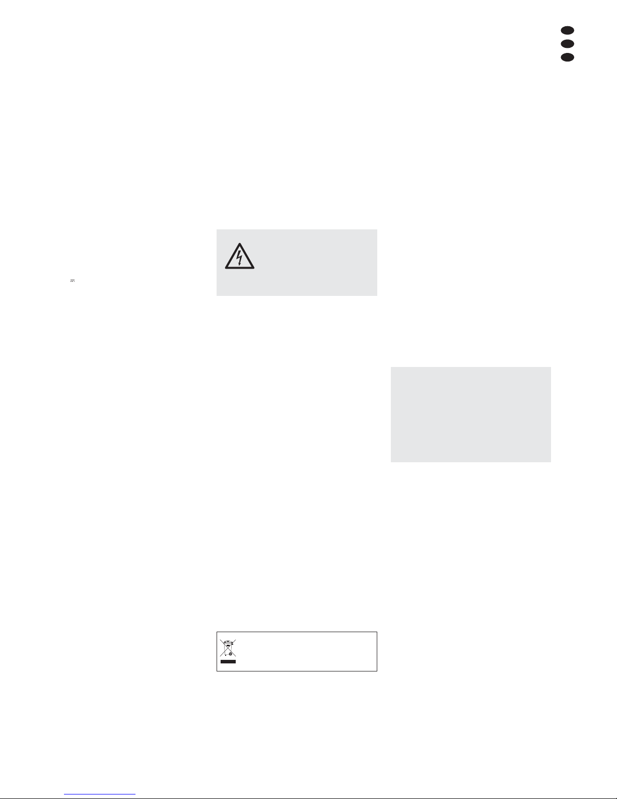
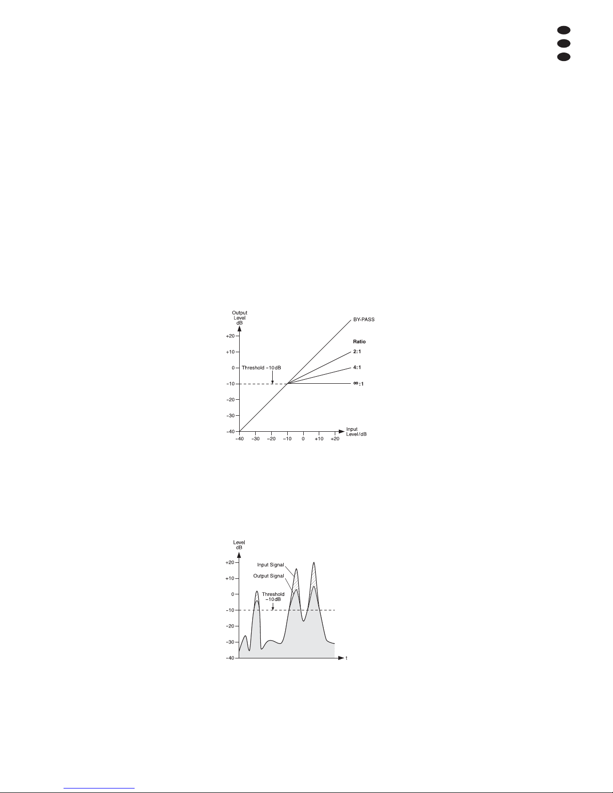
40 Regler RATIO zum Einstellen des Kompres-
sionsverhältnisses
41 Regler THRESHOLD zum Einstellen des Ein-
satzpunktes (Schwellwert), ab dem das Sum-
mensignal komprimiert werden soll
42 Taste PFL/AFL – MAIN mit Kontroll-LED zur
Auswahl des Signals, das die Pegelanzeige
(43) anzeigen und das auf den Kopfhörer-
ausgang PHONES (19) gegeben werden soll
Taste ausgerastet:
Das Summensignal nach dem Fader MAIN
MIX (36) wird angezeigt und auf den Kopf-
hörerausgang gegeben.
Taste hineingedrückt:
Das Signal eines Kanals, dessen Taste
PFL (3) oder AFL (29, 37) gedrückt ist, wird
angezeigt und auf den Kopfhörerausgang
gegeben.
43 Pegelanzeige; zeigt den Pegel des Signals
an, das zum Abhören über den Kopfhörer-
ausgang PHONES (19) gewählt ist, siehe
Position 42
44 Betriebsanzeige POWER
45 Line-Ausgang MAIN OUT für das Summen-
signal (6,3-mm-Klinkenbuchsen, sym.)
1.4 Rückseite
46 Netzbuchse zum Anschluss an eine Steck-
dose (230 V~/50 Hz) über das beiliegende
Netzkabel
47 Halterung für die Netzsicherung
Eine geschmolzene Sicherung nur durch
eine gleichen Typs ersetzen.
48 Ein-/Ausschalter POWER
49 Lautsprecherbuchsen (6,3-mm-Klinke)
alternativ zu den Anschlüssen (50)
50 Lautsprecherbuchsen (SPEAKON®-kompati-
bel) alternativ zu den 6,3-mm-Klinkenbuch-
sen (49)
2 Hinweise für den
sicheren Gebrauch
Das Gerät entspricht allen relevanten Richtlinien
der EU und ist deshalb mit gekennzeichnet.
Beachten Sie auch unbedingt folgende Punkte:
GVerwenden Sie das Gerät nur im Innenbereich
und schützen Sie es vor Tropf- und Spritzwas-
ser, hoher Luftfeuchtigkeit und Hitze (zulässi-
ger Einsatztemperaturbereich 0 – 40 °C).
GStellen Sie keine mit Flüssigkeit gefüllten Ge-
fäße z. B. Trinkgläser, auf das Gerät.
GDie in dem Gerät entstehende Wärme muss
durch Luftzirkulation abgegeben werden.
Decken Sie darum die Lüftungsöffnungen des
Gehäuses nicht ab.
GNehmen Sie das Gerät nicht in Betrieb und
ziehen Sie sofort den Netzstecker aus der
Steckdose,
1. wenn sichtbare Schäden am Gerät oder am
Netzkabel vorhanden sind,
2. wenn nach einem Sturz oder Ähnlichem der
Verdacht auf einen Defekt besteht,
3. wenn Funktionsstörungen auftreten.
Geben Sie das Gerät in jedem Fall zur Repa-
ratur in eine Fachwerkstatt.
G
Ziehen Sie den Netzstecker nie am Kabel aus
der Steckdose, fassen Sie immer am Stecker
an.
GVerwenden Sie für die Reinigung nur ein tro-
ckenes, weiches Tuch, niemals Wasser oder
Chemikalien.
GWird das Gerät zweckentfremdet, nicht richtig
angeschlossen, falsch bedient oder nicht fach-
gerecht repariert, kann keine Haftung für
daraus resultierende Sach- oder Personen-
schäden und keine Garantie für das Gerät
übernommen werden.
3 Einsatzmöglichkeiten
Dieses Audio-Mischpult mit integrierter Stereo-
Endstufe (Klasse D, 2 × 400 WRMS an 4-Ω-Laut-
sprechern) ist für vielfältige Beschallungs- und
Aufnahmezwecke geeignet. Es ist als Tischgerät
ausgelegt und verfügt über 6 Mono- und 3 Ste-
reo-Eingangskanäle zum Anschluss von Mikro-
fonen (auch phantomgespeisten) und Tonquel-
len mit Line-Ausgangspegel (z. B. Instrumente,
Abspielgeräte). Ein weiterer Stereo-Eingangska-
nal kann z. B. für die Wiedergabe eines Aufnah-
megerätes genutzt werden.
Die Eingangssignale lassen sich auf einen
Stereo-Summenkanal und auf zwei Ausspiel-
wege mischen. Zum Zumischen von Effekten ist
ein digitaler Effektprozessor vorhanden. Die
Tonmischung lässt sich über einen Kopfhörer
abhören. Außerdem können einzelne Kanalsig-
nale über den Kopfhörer vorgehört werden.
4 Geräte anschließen
Um Störgeräusche zu vermeiden, vor dem Her-
stellen/Trennen von Verbindungen das Misch-
pult ausschalten oder die Fader MONITOR (35)
und MAIN MIX (36) ganz zuziehen sowie den
Regler PHONES (15) ganz zudrehen.
4.1 Tonquellen
In den Eingangskanälen kann nicht zwischen dem
Mikrofoneingang (13) und dem Line-Eingang
(11, 12) umgeschaltet werden. Darum pro Kanal
nur einen von beiden Eingängen anschließen.
4.1.1 Mikrofone
Mikrofone an die symmetrisch beschalteten
XLR-Buchsen MIC (13) anschließen. Für phan-
tomgespeiste Mikrofone lässt sich für jeweils
drei Mikrofoneingänge mit den Schaltern PHAN-
TOM (14) eine 48-V-Phantomspeisung einschal-
ten. Bei aktivierter Phantomspeisung leuchtet
die LED neben dem Schalter.
4.1.2 Line-Tonquellen
Tonquellen mit Line-Signalpegel (z. B. Empfän-
ger von drahtlosen Mikrofonsystemen, Effektge-
räte, Instrumente, Abspielgeräte) an die 6,3-mm-
Klinkenbuchsen LINE IN (11, 12) der Eingangs-
kanäle anschließen. Die Buchsen sind symme-
trisch beschaltet. Es lassen sich aber auch Gerä-
te mit asymmetrisch beschaltetem Ausgang über
zweipolige Klinkenstecker anschließen.
—Mono-Geräte an die Buchsen (12) der Mono-
Kanäle CH 1 bis CH 6 anschließen.
—Stereo-Geräte an die Buchsen (11) der Ste-
reo-Kanäle CH 7-8, CH 9-10 und CH 11-12
anschließen. Soll an einen Stereo-Kanal ein
Mono-Gerät angeschlossen werden, nur die
obere Buchse L (MONO) verwenden. Das
Mono-Signal wird dann intern auf den rech-
ten und linken Kanal geleitet.
Reichen die Eingangskanäle nicht aus, können
zum Anschluss von zusätzlichen Line-Quellen
auch folgende Stereo-Eingänge genutzt werden:
1. der Eingang AUX RET (25)
Beim Anschluss eines Mono-Geräts nur die
Buchse L (MONO) verwenden, das Mono-
Signal wird dann intern auf den linken und
rechten Kanal geleitet.
2. der Eingang TAPE IN (18)
z. B. zum Anschluss eines CD-Spielers für
Hintergrundmusik in den Spielpausen
Vorsicht: Bei eingeschalteter Phantomspei-
sung darf kein Mikrofon mit asymmetrischem
Ausgang angeschlossen sein, da dieses be-
schädigt werden kann.
Um Schaltgeräusche in den Lautsprechern und
im Kopfhörer zu vermeiden, die Phantomspei-
sung nur ein- oder ausschalten, wenn das
Mischpult ausgeschaltet ist oder die zugehöri-
gen Tasten MUTE (4) hineingedrückt sind und
der Regler PHONES (15) zugedreht ist.
Soll das Gerät endgültig aus dem
Betrieb genommen werden, übergeben
Sie es zur umweltgerechten Entsor-
gung einem örtlichen Recyclingbetrieb.
WARNUNG Dieses Gerät wird mit lebensge-
fährlicher Netzspannung versorgt.
Nehmen Sie deshalb nie selbst
Eingriffe am Gerät vor und stecken
Sie nichts durch die Lüftungsöff-
nungen. Es besteht die Gefahr
eines elektrischen Schlages.

6
D
A
CH
4.2 Effektgerät
Über den Ausspielweg AUX 2, der gleichzeitig
als Effektweg für den internen Effektprozessor
dient, können Signalanteile aus den Eingangs-
kanälen ausgekoppelt, über ein Effektgerät (z. B.
Hallgerät) bearbeitet und über die Return-Ein-
gänge wieder in das Mischpult zurückgeführt
werden. Der Signalabgriff für diesen Ausspiel-
weg ist post-fader, d. h. das Kanalsignal wird
nach dem Fader (1) auf den Ausspielweg
gemischt. Auf diese Weise ist der Effektanteil
eines Kanals immer proportional zum eingestell-
ten Kanalpegel.
1) Den Eingang des Effektgerätes über einen
6,3-mm-Klinkenstecker an den Mono-Aus-
gang FX SEND (26) anschließen.
2) Das vom Effektgerät kommende Signal auf
den Eingang AUX RET (25) zurückführen.
Hinweis: Beim Anschluss eines Mono-Geräts nur
die Buchse L (MONO) verwenden. Das Signal wird
dann intern auf den rechten und linken Kanal ge-
leitet.
3) Alternativ kann das Signal vom Effektgerät
auch auf den Line-Eingang eines freien Ein-
gangskanals gegeben werden.
Soll das Effektsignal auch auf den Moni-
torweg AUX 1 gemischt werden, muss unbe-
dingt ein freier Eingangskanal benutzt wer-
den, weil dieses nur mit den Regler AUX 1
MON (8) erfolgen kann.
4.3 Aufnahmegerät
Ein Aufnahmegerät kann an die Buchsen TAPE
IN und TAPE OUT (18) angeschlossen werden
(L = linker Kanal, R = rechter Kanal):
1) Für Aufnahmen den Eingang des Gerätes an
die Cinch-Buchsen TAPE OUT anschließen.
Hier liegt das mit dem Fader MAIN MIX (36)
eingestellte Summensignal an.
2) Für die Wiedergabe den Ausgang des Gerä-
tes an die Cinch-Buchsen oder an die 3,5-mm-
Klinkenbuchse TAPE IN anschließen. Das
Signal der Buchsen TAPE IN lässt sich mit
dem Fader des Kanals CH 13-14 (1) auf das
Summensignal mischen.
4.4 Kopfhörer
Über einen Kopfhörer lassen sich folgende Sig-
nale abhören:
– die Signale der einzelnen Eingangskanäle
– das Summensignal
– das Signal des Ausspielwegs AUX 1
– das Eingangssignal der Buchsen AUX RET (25)
Den Kopfhörer (Mindestimpedanz 8 Ω) an die
Buchse PHONES (19) anschließen.
4.5 Monitoranlage für die Musiker
Beim Einsatz einer Monitoranlage für die Büh-
nenbeschallung lässt sich der Ausspielweg
AUX 1 als Monitorweg nutzen. Der Signalabgriff
für diesen Ausspielweg ist pre-fader, d. h. das
Kanalsignal wird vor dem Fader (1) auf den Aus-
spielweg gemischt. So erhalten die Musiker über
die Bühnenlautsprecher ein separat abgemisch-
tes Musiksignal.
Den Verstärker der Monitoranlage oder eine
aktive Monitorbox mit der Buchse MONITOR
OUT (33) verbinden. Alternativ kann auch ein
Kanal der internen Endstufe das Monitorsignal
verstärken, wenn die Saalbeschallung nur
monofon über den anderen Kanal erfolgen soll.
Dazu den Schalter AMPLIFIER ASSIGN (17) in
die mittlere Position schieben. Zum Anschluss
der Lautsprecher siehe Kapitel 4.7.
4.6 Zusätzlicher Verstärker
Für die Beschallung des Publikums kann die
interne Endstufe verwendet werden. Reicht
diese nicht aus oder soll das Summensignal z. B.
in einem weiteren Raum zu hören sein, einen
zusätzlichen Verstärker an den Ausgang MAIN
OUT (45) anschließen. Hier liegt das mit dem
Fader MAIN MIX (36) eingestellte Summensig-
nal an. Alternativ oder zusätzlich können hierfür
auch die Cinch-Buchsen TAPE OUT (18) ver-
wendet werden.
4.7 Lautsprecher
Für den Anschluss der Lautsprecher können die
Klinkenbuchsen (49) oder die SPEAKON®-kom-
patiblen Buchsen (50) verwendet werden. Wer-
den die SPEAKON®-kompatiblen Buchsen ge-
nutzt, den jeweiligen Lautsprecherstecker nach
dem Einstecken in die Buchse nach rechts dre-
hen, bis er einrastet. Zum späteren Herauszie-
hen den Sicherungsriegel am Stecker zurückzie-
hen und den Stecker nach links drehen.
Der korrekte Anschluss der Lautsprecher
richtet sich nach der gewünschten Betriebsart
für die Endstufe, die mit dem Schalter AMPFLI-
FIER ASSIGN (17) eingestellt wird:
Stereobetrieb (obere Schalterposition)
Die Endstufe verstärkt das Stereo-Summensig-
nal. Die Lautsprecher (Impedanz min. 4 Ω) an
die Buchse A (linker Kanal) und an die Buchse B
(rechter Kanal) anschließen.
2-Kanal-Betrieb (mittlere Schalterposition)
Die Endstufe verstärkt im Kanal A das Mono-
Summensignal und im Kanal B das Signal des
Ausspielwegs AUX 1 zur Beschallung der Musi-
ker. Den Lautsprecher (Impedanz min. 4 Ω) für
die Beschallung des Publikums an die Buchse A
anschließen und den Lautsprecher (Impedanz
min. 4 Ω) für die Beschallung der Musiker an die
Buchse B.
Brückenbetrieb (untere Schalterposition)
Die Endstufe verstärkt das Mono-Summensignal
mit der doppelten Leistung. Der Lautsprecher
(Impedanz min. 8 Ω) oder eine Lautsprecher-
gruppe mit einer Gesamtimpedanz von 8 Ω kann
nur an die SPEAKON®-kompatible Buchse A
wie folgt angeschlossen werden:
Kontakt 1+ für den Pluspol
Kontakt 2+ für den Minuspol
Abb. 8 SPEAKON®-kompatibler Stecker
Anschluss für den Brückenbetrieb
4.8 Pultleuchte
Um das Mischpult zu beleuchten, lässt sich in
die XLR-Buchse LAMP (34) eine Schwanenhals-
leuchte (12 V /500 mA max.) stecken, z. B. das
Modell GNL-304, GNL-305 oder GNL-314 von
„img Stage Line“. Die Leuchte wird zusammen
mit dem Mischpult ein- und ausgeschaltet.
4.9 Fußtaster für den Effektprozessor
Um den internen Effektprozessor z. B. von der
Bühne aus ein- und ausschalten zu können,
lässt sich ein Fußtaster (z. B. FS-60 von
MONACOR) an die zweipolige 6,3-mm-Klinken-
buchse FOOT SWITCH (27) anschließen.
4.10 Stromversorgung
Das Mischpult über die Netzbuchse (46) mit
dem beiliegenden Netzkabel an eine Steckdose
(230 V~/50 Hz) anschließen.
5 Bedienung
5.1 Ein- und Ausschalten
1) Um Einschaltgeräusche und eine zu hohe
Lautstärke zu vermeiden, vor der Inbetrieb-
nahme die Fader MONITOR (35) und MAIN
MIX (36) ganz zuziehen sowie den Regler
PHONES (15) ganz zudrehen.
2) Je nachdem welcher Mikrofontyp ange-
schlossen ist, die 48-V-Phantomspeisung mit
den Schaltern PHANTOM (14) entweder ein-
oder ausschalten (Kapitel 4.1.1).
3) Wird die interne Endstufe verwendet, die kor-
rekte Stellung des Schalters AMPFLIFIER
ASSIGN (17) überprüfen (Kapitel 4.7)
und die Endstufe mit dem Schalter POWER
AMP (16) einschalten. Wird die Endstufe
nicht verwendet, die Endstufe ausschalten.
4) Zum Ein- und Ausschalten des Mischpults
den Netzschalter POWER (48) betätigen. Bei
eingeschaltetem Gerät leuchten die Betriebs-
anzeige POWER (44) und das Display (24).
5.2 Eingangssignale mischen
Die folgenden Bedienschritte dienen nur als
Hilfestellung, es sind auch andere Vorgehens-
weisen möglich.
1) Zuerst folgende Grundeinstellung vornehmen.
a) Alle Tasten PAD (10) ausrasten.
b) Alle Klangregler HIGH, MID, LOW (9) und
alle Schieberegler der Equalizer (31, 32)
in die Mittelposition stellen.
c) Alle Regler AUX 1 MON (8) und AUX 2 FX
(7) für die Ausspielwege ganz zudrehen.
d) Alle Panoramaregler PAN (5) und alle
Balanceregler BAL (6) in die Mitte drehen.
e) Den Regler FX TO MON (22) ganz zudre-
hen.
f) Alle Tasten MUTE (4), PFL (3), AFL (29,
37) sowie die Tasten COMP/LIM (38) und
PFL/AFL – MAIN (42) ausrasten.
g) Alle Kanalfader (1) sowie die Fader FX TO
MAIN (20) und AUX RET (28) zuziehen.
2) Auf den Kanal, der am lautesten zu hören
sein soll, ein Signal geben (z. B. in ein Mikro-
fon singen, ein Instrument spielen) und den
zugehörigen Fader (1) vorerst ca. auf die
Position 0 dB aufziehen.
Der Kanal ist optimal ausgesteuert, wenn
bei Signalspitzen die LED PEAK (2) kurz auf-
leuchtet. Leuchtet sie länger, wird der Kanal
übersteuert. Dann das Eingangssignal mit
der Taste PAD (10) abschwächen oder den
Ausgangspegel der Signalquelle verringern.
3) Den Fader MAIN MIX (36) so weit aufziehen,
dass die folgenden Einstellungen gut über die
angeschlossenen Lautsprecher zu hören
sind oder über einen an der Buchse PHONES
(19) angeschlossenen Kopfhörer. Die Kopf-
hörerlautstärke zusätzlich mit dem Regler
PHONES (15) einstellen.
4) Den Klang des Kanalsignals mit den Reglern
HIGH, MID und LOW (9) einstellen.
1+ =2
-
1
-
2+ =
VORSICHT Stellen Sie die Lautstärke der
Lautsprecher und des Kopfhörers
nie sehr hoch ein. Hohe Lautstär-
ken können auf Dauer das Gehör
schädigen! Das Ohr gewöhnt sich
an hohe Lautstärken und empfin-
det sie nach einiger Zeit als nicht
mehr so hoch. Erhöhen Sie darum
eine hohe Lautstärke nach der
Gewöhnung nicht weiter.

7
5) Bei einem Mono-Kanal mit dem Panorama-
regler PAN (5) das Mono-Signal im Stereo-
Klangbild platzieren oder bei einem Stereo-
Kanal mit dem Regler BAL (6) die Balance
des Stereo-Signals einstellen.
6) Schrittweise alle weiteren Kanalsignale da-
zumischen und jeweils den Klang einstellen
sowie die Panorama- oder Balanceeinstel-
lung vornehmen. Die Fader nicht benutzter
Kanäle immer ganz zuziehen.
Tipps
1. Kann ein Kanalfader beim Dazumischen eines
Signals nur gering aufgezogen werden, weil der
Eingangspegel sehr groß ist, die zugehörige
Taste PAD drücken oder den Ausgangspegel der
Signalquelle verringern. Dadurch kann ein länge-
rer Faderweg für eine feinere Einstellung genutzt
werden.
2. Bei der Klangeinstellung kann es hilfreich sein,
andere Kanäle zeitweise mit der MUTE-Taste (4)
stummzuschalten. Zur Kontrolle leuchtet die LED
neben der Taste. Ein einzelner Kanal lässt sich
aber auch optimal über einen Kopfhörer abhören
und einstellen (Kapitel 5.6).
7) Zum Zumischen von Effekten siehe Kap. 5.5.
8) Das Eingangssignal der Buchsen TAPE IN
(18) lässt sich mit dem Fader (1) des Kanals
CH 13-14 auf die Signalsumme mischen.
Hinweis: Wird während einer Aufnahme über die
Buchsen TAPE OUT das Aufnahmesignal als Ein-
gangssignal auf die Buchsen TAPE IN gegeben, die
Taste MUTE des Kanals CH 13-14 hineindrücken,
damit keine Rückkopplung auftritt.
9) Die endgültige Lautstärke des Summensig-
nals mit dem Fader MAIN MIX einstellen. Das
Signal kann mit der Pegelanzeige (43) kon-
trolliert werden, wenn die Taste PFL/AFL –
MAIN unter der Anzeige nicht hineingedrückt
ist. Bei Übersteuerung leuchten die roten
LEDs CLIP auf; den Fader MAIN MIX dann
entsprechend zurückziehen.
10) Der Klang des Summensignals lässt sich mit
dem 7-Band-Equalizer MAIN EQ an die
Raumakustik anpassen. Dazu den Equalizer
mit der Taste MAIN EQ (39) einschalten und
den Klang mit den Schiebereglern (31) ein-
stellen.
Hinweis: Das Signal am Ausgang TAPE OUT (18)
wird ebenfalls durch den Equalizer beeinflusst. Bei
einer Aufnahme den Equalizer mit der Taste MAIN
EQ ggf. ausschalten.
11) Zum Stummschalten eines Kanals, z. B. wäh-
rend einer Spielpause, die zugehörige Taste
MUTE drücken.
5.3 Signalkompressor verwenden
Die Dynamik des Summensignals lässt sich
durch den integrierten Kompressor reduzieren.
Er schwächt den Pegel oberhalb einer einstell-
baren Schwelle ab. Dies ist z. B. erforderlich,
wenn die Dynamik des Audiosignals größer ist
als das Aufnahme- oder Verstärkersystem
erlaubt oder eine geringe Dynamik (z. B. für Hin-
tergrundmusik) erwünscht ist. Auch lassen sich
Signalspitzen abschwächen, um eine höhere
Aussteuerbarkeit und damit eine höhere Durch-
schnittslautstärke zu erreichen.
1) Den Kompressor mit der Taste COMP/LIM
(38) einschalten. Die LED neben der Taste
leuchtet.
2) Den Einsatzpunkt (Schwellwert) der Kom-
pression mit dem Regler THRESHOLD (41)
einstellen. Das Kompressionsverhältnis mit
dem Regler RATIO (40) einstellen:
Position „4“:
Das Verhältnis beträgt 4 : 1; eine Eingangspe-
geländerung von 8 dB oberhalb des Thresh-
old-Wertes bewirkt eine Ausgangspegelän-
derung von 2 dB.
Position „∞“:
Der Kompressor arbeitet als Signalbegrenzer
(Limiter); das Ausgangssignal wird etwa auf
den mit dem Regler THRESHOLD eingestell-
ten Wert begrenzt.
Tipp: Je höher der Schwellwert und je niedriger das
Kompressionsverhältnis eingestellt wird, desto
mehr bleibt die natürliche Dynamik erhalten.
3) Die LED neben dem Regler THRESHOLD
leuchtet auf, wenn das Eingangssignal des
Kompressors den eingestellten Schwellwert
überschreitet und das Ausgangssignal kom-
primiert wird. Die Pegelanzeige (43) kann
ebenfalls als Einstellhilfe dienen. Um den
Ausgangspegel ablesen zu können, die
Taste PFL/AFL – MAIN (42) unter der An-
zeige ausrasten.
Die Abbildung 9 zeigt als Beispiel den Aus-
gangspegel in Abhängigkeit vom Eingangs-
pegel bei einem Schwellwert von
-
10 dB und
verschiedenen Kompressionsverhältnissen.
Abb. 9 Steuerkennlinien des Kompressors
bei einem Schwellwert von
-
10 dB
Die Abbildung 10 zeigt ein Eingangssignal
und das resultierende Ausgangssignal bei
einem Schwellwert von
-
10 dB und einem
Kompressionsverhältnis von 2 : 1. Unterhalb
des Schwellwertes bleibt das Signal unver-
ändert und oberhalb wird es um den Faktor 2
komprimiert.
Abb. 10 Ein- und Ausgangssignal des Kompressors
bei einem Schwellwert von
-
10 dB und
einem Kompressionsverhältnis von 2 : 1
5.4 Monitor-Ausspielweg einstellen
1) Den Fader MONITOR (35) für die Lautstärke
der Monitormischung so weit aufziehen, dass
das Monitorsignal für die folgenden Einstel-
lungen gut über die Monitoranlage oder über
die angeschlossenen Lautsprecher zu hören
ist.
2) Mit den Reglern AUX 1 MON (8) die Kanal-
signale auf den Monitorweg mischen: Die
Regler je nach gewünschtem Lautstärkever-
hältnis der Kanäle aufdrehen. In den zuge-
hörigen Eingangskanälen muss die Taste
MUTE (4) ausgerastet sein.
3) Mit dem Regler FX TO MON (22) lässt sich
das Effektsignal des internen Effektprozes-
sors (Kap. 5.5.1) auf den Monitorweg
mischen.
4) Die endgültige Lautstärke des Monitorsignals
mit dem Fader MONITOR einstellen.
5) Der Klang des Monitorsignals lässt sich mit
dem 7-Band-Equalizer MONITOR EQ opti-
mieren. Dazu den Equalizer mit der Taste
MON EQ (30) einschalten und den Klang mit
den Schiebereglern einstellen (32).
6) Soll der Monitorweg über einen Kopfhörer ab-
gehört werden und die Pegelanzeige (43) das
Monitorsignal anzeigen, die Taste AFL (37)
über dem Fader MONITOR und die Taste
PFL/AFL – MAIN (42) unter der Anzeige hin-
eindrücken (Kap. 5.6).
D
A
CH

D
A
CH
8
5.5 Effekte zumischen
5.5.1 Verwendung des internen
Effektprozessors
Mit dem internen Effektprozessor lassen sich
100 verschiedene Effekte erzeugen, die auf das
Summensignal und auf den Monitor-Ausspiel-
weg AUX 1 gemischt werden können. Als Effekt-
weg für den Effektprozessor dient der Ausspiel-
weg AUX 2.
1) Damit die Effekteinstellungen zu hören sind,
den Fader FX TO MAIN (20) vorerst ungefähr
in die Mittelposition schieben.
2) Den Drehknopf PROGRAM (23) links- oder
rechtsherum drehen, bis die Nummer des
gewünschten Effekts (Abb. 11 Effekt-
übersicht) blinkend im Display (24) angezeigt
wird. Die Wahl durch Drücken des Knopfes
bestätigen: Die Nummer hört auf zu blinken,
der Effekt ist eingeschaltet.
3) Mit den Reglern AUX 2 FX (7) die Signale der
Eingangskanäle auf den Effektweg mischen.
Mit diesen Reglern lässt sich für jeden Kanal
getrennt die gewünschte Effektintensität ein-
stellen. Der Signalabgriff ist nach dem Fader
(1), d. h. der Effektanteil eines Kanals ist
immer proportional zum eingestellten Kanal-
pegel.
4) Die LED PEAK/MUTE über dem Fader FX TO
MAIN neben der Taste MUTE (21) dient bei
eingeschaltetem Effektprozessor als Über-
steuerungsanzeige. Mit ihr lässt sich die Aus-
steuerung grob kontrollieren. Leuchtet sie
auf, die Regler AUX 2 FX entsprechend zu-
rückdrehen.
5) Das Effektsignal mit dem Fader FX TO MAIN
auf die Summenkanäle mischen und wenn
gewünscht, mit dem Regler FX TO MON (22)
auch auf den Ausspielweg AUX 1.
6) Der Effektprozessor lässt sich mit einem an
der Buchse FOOT SWITCH (27) angeschlos-
senen Fußtaster und mit der Taste MUTE
(21) aus- und wieder einschalten (die Taste
rastet nicht ein). Ist er ausgeschaltet, leuchtet
zur Kontrolle die LED PEAK/MUTE neben
der Taste MUTE.
5.5.2 Externes Effektgerät
Das Effektgerät muss über den Ausgang FX
SEND (26) und den Eingang AUX RET (25) oder
den Line-Eingang eines freien Eingangskanals
angeschlossen sein, Kapitel 4.2.
1) Damit die Effekteinstellungen zu hören sind,
den Fader AUX RET (28) vorerst ungefähr in
die Mittelposition schieben. Oder, wenn ein
freier Eingangskanal als Effekteingang be-
nutzt wird, den zugehörigen Kanalfader (1)
ungefähr in die Mittelposition schieben.
2) Am Effektgerät den gewünschten Effekt ein-
schalten.
3) Mit den Reglern AUX 2 FX (7) die Signale der
Eingangskanäle auf den Effektweg mischen.
Mit diesen Reglern lässt sich für jeden Kanal
getrennt die gewünschte Effektintensität ein-
stellen. Der Signalabgriff ist nach dem Fader
(1), d. h. der Effektanteil eines Kanals ist
immer proportional zum eingestellten Kanal-
pegel.
Hinweise
1. Ist das Effektgerät am Line-Eingang eines Ein-
gangskanals angeschlossen, den Regler AUX 2
FX des betreffenden Kanals ganz zudrehen,
sonst tritt eine Rückkopplung auf.
2. Die Signale des Effektwegs werden auch auf den
Eingang des internen Effektprozessors gegeben
(Kap. 5.5.1). Deshalb je nach Bedarf die
Intensität des internen Effekts separat mit dem
Regler FX TO MAIN (20) einstellen oder den
internen Effekt mit der Taste MUTE (21) stumm-
schalten.
4) Das vom Effektgerät kommende Signal mit
dem jeweiligen Eingangsregler zumischen;
mit ihm lässt sich die Effektintensität für alle
Kanäle gemeinsam einstellen:
—Ist das Effektgerät am Eingang AUX RET
(25) angeschlossen, das Effektsignal mit
dem Regler AUX RET (28) auf das Sum-
mensignal mischen.
—Ist das Effektgerät am Line-Eingang (11,
12) eines Eingangskanals angeschlossen,
das Effektsignal mit dem entsprechenden
Kanalfader (1) auf das Summensignal
mischen. Wenn gewünscht, kann das
Effektsignal mit dem zugehörigen Regler
AUX 1 MON (8) auch auf den Monitoraus-
spielweg AUX 1 gemischt werden.
5.6 Abhören über einen Kopfhörer
Zum Abhören über einen Kopfhörer an der
Buchse PHONES (19) lassen sich folgende Sig-
nale anwählen:
1. das Summensignal post-fader, d. h. nach dem
Fader MAIN MIX (36)
2. die Signale der einzelnen Eingangskanäle
pre-fader, d. h. vor dem Kanalfader (1), der
Taste MUTE (4) und dem Regler PAN (5)
oder BAL (6)
3. das Signal des Ausspielwegs AUX 1 post-
fader, d. h. nach dem Fader MONITOR (35)
4. das Eingangssignal der Buchsen AUX RET
(25) post-fader, d. h. nach dem Fader AUX
RET (28)
Die Pegelanzeige (43) zeigt immer das Signal
an, welches zum Abhören ausgewählt ist.
1) Zum Abhören des Summensignals die
Taste PFL/AFL – MAIN (42) unter der Pegel-
anzeige ausrasten. Die LED über der Taste
darf nicht leuchten.
2) Zum Abhören eines Eingangskanals die
Taste PFL (3) des Kanals drücken. Zur Kon-
trolle leuchtet die LED neben der Taste.
Zusätzlich die Taste PFL/AFL – MAIN (42)
unter der Pegelanzeige hineindrücken. Die
LED über der Taste leuchtet.
3) Zum Abhören des Ausspielwegs AUX 1 für
die Beschallung der Musiker die Taste AFL
(37) über dem Fader MONITOR (35) drü-
cken. Zusätzlich muss die Taste PFL/AFL –
MAIN unter der Pegelanzeige hineingedrückt
sein.
4) Zum Abhören des Eingangssignals der
Buchsen AUX RET die Taste AFL (29) über
dem Fader AUX RET (28) drücken. Zusätz-
lich muss die Taste PFL/AFL – MAIN unter
der Pegelanzeige hineingedrückt sein.
Nummer Name Effekt Parameter
00 – 09 Vocal Nachhalleffekt, besonders für Gesangsanwendungen geeignet Abklingzeit 0,8 – 0,9 s, Pre-Delay-Zeit 10 – 45 ms
10 – 19 Small Room Nachhalleffekt: Simulation eines kleinen bis mittelgroßen Raums Abklingzeit 0,7 – 2,1 s, Pre-Delay-Zeit 20 – 45 ms
20 – 29 Large Hall Nachhalleffekt: Simulation eines großen Saals Abklingzeit 3,6 – 5,4 s, Pre-Delay-Zeit 23 – 55 ms
30 – 39 Echo Echo-Effekt Delay-Zeit 145 – 205 ms
40 – 49 Echo + Verb Kombination von Echo-Effekt und Nachhalleffekt Delay-Zeit 208 – 650 ms, Abklingzeit 1,7 – 2,7 s
50 – 59 Flange + Verb Kombination von Flanger-Effekt und Nachhalleffekt Geschwindigkeit 0,8 – 2,52 Hz, Abklingzeit 1,5 – 2,9 ms
60 – 69 Plate Simulation einer klassischen, hell klingenden Hallplatte Abklingzeit 0,9 – 3,6 s
70 – 79 Chorus + GTR Gitarreneffekt: Chorus Geschwindigkeit 0,92 – 1,72 Hz
80 – 89 Rotary + GTR Gitarreneffekt: Rotary (Leslie-Effekt) Modulationstiefe 20 – 80 %
90 – 99 Tremolo + GTR Gitarreneffekt: Tremolo Geschwindigkeit 0,6 – 5 Hz
Abb. 11 Effektübersicht

6 Technische Daten
Blockschaltbild siehe Seite 49.
Ausgangsleistung
Sinusleistung
an 4-Ω-Lautsprecher:2 × 400 W
an 8-Ω-Lautsprecher:2 × 300 W
Brückenbetrieb: . . . . 1 × 700 W an 8 Ω
Maximale Leistung: . . 2 × 600 W an 4 Ω
Eingänge
(Empfindlichkeit/Impedanz; Anschluss)
Mic: . . . . . . . . . . . . . . 1 mV/3 kΩ;
XLR, symmetrisch
Line (Mono-Kanal): . . 10 mV/27 kΩ;
6,3-mm-Klinke, sym.
Line (Stereo-Kanal): . . 75 mV/10 kΩ;
6,3-mm-Klinke, sym.
Tape In: . . . . . . . . . . . 100 mV/20 kΩ; Cinch,
3,5-mm-Klinke, asym.
Aux Return: . . . . . . . . 80 mV/26 kΩ;
6,3-mm-Klinke, sym.
Ausgänge
(Pegel/Impedanz; Anschluss)
Main Out, stereo: . . . . 1,5 V (bei Anzeige
0 dB)/120 Ω;
6,3-mm-Klinke, sym.
Monitor Out, mono: . . 10 V/120 Ω;
6,3-mm-Klinke, asym.
Tape Out, stereo: . . . . 800 mV/1 kΩ; Cinch
FX Send, mono: . . . . . 10 V/120 Ω;
6,3-mm-Klinke, asym.
Kopfhörerimpedanz: . . . ≥ 8 Ω
Frequenzbereich: . . . . . 20 – 20 000 Hz
Klirrfaktor: . . . . . . . . . . . < 0,04 %
Störabstand: . . . . . . . . . 89 dB
Übersprechen: . . . . . . .
-
63 dB
Klangregler für CH 1 – 12
Bässe: . . . . . . . . . . . . ±15 dB bei 80 Hz
Mitten: . . . . . . . . . . . . ±12 dB bei 2,5 kHz
Höhen: . . . . . . . . . . . . ±15 dB bei 12 kHz
Equalizer für
Main-Mix und Monitor: . ±15 dB bei
63/160/400 Hz/
1/2,5/6,3/16 kHz
Kompressor
Schwellwert
(Threshold)
:
-
40 dB bis +22 dB
Ratio: . . . . . . . . . . . . . 2 : 1 bis ∞ : 1
Ansprechzeit
(Attack)
: .1ms
Rückstellzeit
(Release)
:2s
Phantomspeisung
für Mic 1 – 9: . . . . . . . . . +48 V
Spannung für Pultleuchte: 12 V /500 mA
Netzspannung: . . . . . . . 230 V~/50 Hz
Leistungsaufnahme
im Leerlauf: . . . . . . . . 65 VA
bei maximaler
Ausgangsleistung: . . . 1250 VA
Einsatztemperatur: . . . . 0 – 40 °C
Abmessungen
(B × H × T): . . . . . . . . . . 465 × 150 × 395 mm
Gewicht: . . . . . . . . . . . . 10,1 kg
6.1 Steckerbelegung
Lautsprecheranschlüsse
für den Stereo- oder 2-Kanalbetrieb
2-poliger 6,3-mm-Klinkenstecker
SPEAKON®-kompatibler Stecker
Lautsprecheranschluss an der Buchse „A“
für den Brückenbetrieb
SPEAKON®-kompatibler Stecker
Mikrofonanschlüsse
XLR-Stecker für symmetrischen Anschluss
Line-Signal-Anschlüsse
3-poliger 6,3-mm-Klinkenstecker
für symmetrischen Anschluss
2-poliger 6,3-mm-Klinkenstecker
für asymmetrischen Anschluss
3-poliger 3,5-mm-Klinkenstecker
für Stereosignale (Tape In)
Kopfhöreranschluss
6,3-mm-Stereo-Klinkenstecker
Anschluss für eine Pultleuchte
XLR-Stecker
Änderungen vorbehalten.
1 = Minuspol 12 V
2 = Pluspol 12 V
3 = frei
1 = Masse
2 = Signal +
3 = Signal
-
T = linker Kanal
R = rechter Kanal
S = Masse
1+ = Pluspol
2+ = Minuspol
1+2
-
1
-
2+
1+2
-
1
-
2+
1+ = Pluspol
1
-
= Minuspol
T = Pluspol
S = Minuspol
T = linker Kanal
R = rechter Kanal
S = Masse
T = Signal
S = Masse
T = Signal +
R = Signal
-
S = Masse
9
Diese Bedienungsanleitung ist urheberrechtlich für MONACOR ®INTERNATIONAL GmbH & Co. KG
geschützt. Eine Reproduktion für eigene kommerzielle Zwecke – auch auszugsweise – ist untersagt.
D
A
CH

All operating elements and connections de-
scribed can be found on the fold-out page 3.
Contents
1 Operating Elements
and Connections . . . . . . . . . . . . . . . . 10
1.1 Input channels . . . . . . . . . . . . . . . . . . . 10
1.2 Effect channel . . . . . . . . . . . . . . . . . . . . 10
1.3 Output panel . . . . . . . . . . . . . . . . . . . . . 11
1.4 Rear panel . . . . . . . . . . . . . . . . . . . . . . 11
2 Safety Notes . . . . . . . . . . . . . . . . . . . . 11
3 Applications . . . . . . . . . . . . . . . . . . . . 11
4 Connecting the Units . . . . . . . . . . . . . 11
4.1 Audio sources . . . . . . . . . . . . . . . . . . . . 11
4.1.1 Microphones . . . . . . . . . . . . . . . . . . . 11
4.1.2 Line audio sources . . . . . . . . . . . . . . 11
4.2 Effect unit . . . . . . . . . . . . . . . . . . . . . . . 12
4.3 Recorder . . . . . . . . . . . . . . . . . . . . . . . . 12
4.4 Headphones . . . . . . . . . . . . . . . . . . . . . 12
4.5 Monitor system for the musicians . . . . . 12
4.6 Additional amplifier . . . . . . . . . . . . . . . . 12
4.7 Speaker systems . . . . . . . . . . . . . . . . . 12
4.8 Console light . . . . . . . . . . . . . . . . . . . . . 12
4.9 Foot pedal for the effect processor . . . . 12
4.10 Power supply . . . . . . . . . . . . . . . . . . . . 12
5 Operation . . . . . . . . . . . . . . . . . . . . . . . 12
5.1 Switching on and off . . . . . . . . . . . . . . . 12
5.2 Mixing input signals . . . . . . . . . . . . . . . 12
5.3 Using the signal compressor . . . . . . . . 13
5.4 Adjusting the monitor send way . . . . . . 13
5.5 Adding effects . . . . . . . . . . . . . . . . . . . . 14
5.5.1 Using the internal effect processor . . 14
5.5.2 External effect unit . . . . . . . . . . . . . . . 14
5.6 Monitoring via headphones . . . . . . . . . 14
6 Specifications . . . . . . . . . . . . . . . . . . . 15
6.1 Plug configuration . . . . . . . . . . . . . . . . . 15
Block diagram . . . . . . . . . . . . . . . . . . . . 49
1 Operating Elements
and Connections
1.1 Input channels
Fig. 1 Mono input channel CH 2
All mono input channels (CH1…CH6)
are identical.
Fig. 2 Stereo input channel CH 9-10
All stereo input channels (CH 7-8,
CH 9-10, CH 11-12 are identical.
Fig. 3 Channel CH 13-14 for a recorder, head-
phones and the power amplifier
1Channel fader to adjust the volume of the
channel and to fade in/fade out the channel
signal
2LED PEAK lights up shortly when the maxi-
mum undistorted signal level has been
reached. If it lights up for a longer period of
time, the channel is overloaded. Then press
the button PAD (10) or reduce the input level.
3Button PFL (with LED indicator) for pre-fader
listening to the selected channel via the
headphones connected to the jack PHONES
(19) and for indicating the channel signal by
means of the level indicators (43). For this,
the button (42) beneath the indicators must
be pressed.
4Button MUTE (with LED indicator) to mute
the channel
5Panorama control PAN to place the mono
signal in the stereo sound
6Balance control BAL for the stereo channels
7Control AUX 2 FX to add the channel signal to
the send way AUX 2 (post-fader)
This send way is used as the effect way for the
internal effect processor and for an external
effect unit.
8Control AUX 1 MON to add the channel signal
to the send way AUX 1 (pre-fader)
This send way is used as the monitor way for
on-stage monitoring by the musicians.
9Equalizer control
LOW for the bass frequencies:
±15 dB at 80 Hz
MID for the mid-frequencies:
±12 dB at 2.5 kHz
HIGH for the high frequencies:
±15 dB at 12 kHz
10 Button PAD to reduce the input level by 20 dB
11 Stereo input LINE IN (6.3 mm jacks, bal.) to
connect a signal source with line output level
(e. g. musical instrument, CD/MP3 player)
Note: When connecting a mono unit, only use the
jack L (MONO). The signal will then be internally
sent to the right and left channels.
12 Mono input LINE IN (6.3 mm jack, bal.) to
connect a signal source with line output level
13 Input MIC to connect a microphone (XLR
jack, bal.)
The phantom power supply can be switched
on for the microphone inputs, item 14.
14 Switch PHANTOM (with LED indicator) to
switch on/off the 48 V phantom power supply
for three microphone inputs
Please observe the warning notes with
regard to the phantom power supply in chap-
ter 4.1.1.
15 Volume control PHONES for headphones
connected to the jack PHONES (19)
16 Switch POWER AMP to switch on/off the
power amplifier
17 Switch AMPLIFIER ASSIGN to assign the
operation mode to the power amplifier
upper position = The power amplifier oper-
ates in stereo mode and amplifies the left
and the right sum signals.
mid position = The power amplifier operates
in 2-channel mode: In the channel A, it
amplifies the mono sum signal; in the
channel B, it amplifies the signal of the
send way AUX 1 for on-stage monitoring
by the musicians.
lower position = The power amplifier oper-
ates in bridged mode (double output power
at an 8 Ω speaker) and amplifies the mono
sum signal.
18 Input and output jacks (RCA) for a recorder;
a 3.5 mm jack is also provided as an input
The sum signal after the fader MAIN MIX (36)
is available at the jacks TAPE OUT.
To add the signal of the jacks TAPE IN to the
sum signal, use the fader CH 13-14 (1).
19 Output PHONES (6.3 mm jack) to connect
stereo headphones (minimum impedance:
8Ω)
1.2 Effect channel
20 Fader FX TO MAIN to add the internal effect
signal to the sum signal
21 Button MUTE to mute the internal effect
processor
When the effect processor is muted, the LED
next to the button will light permanently.
When the effect processor is switched on, the
LED will indicate any overload of the proces-
sor that might occur.
22 Control FX TO MON to add the internal effect
signal to the signal of the send way AUX 1 for
on-stage monitoring by the musicians
23 Knob PROGRAM to select the effect: Turn
the knob until the effect number starts flash-
ing on the display (24); then briefly press the
knob to confirm.
24 Display to indicate the effect number selected
25 Input AUX RET (6.3 mm jacks, bal.), can be
used as an input for an effect unit or for an
additional line audio source
To add the input signal to the sum signal, use
the fader AUX RET (28).
Note: When connecting a mono unit, only use the
jack L (MONO). The signal will then be internally
sent to the right and left channels.
26 Output FX SEND (6.3 mm jack, unbal.) for the
effect send way AUX 2
27 Connection FOOT SWITCH (6.3 mm jack,
2 poles) for a foot pedal to switch on/off the
internal effect processor
10
GB

1.3 Output panel
28 Fader AUX RET to add the signal at the input
AUX RET (25) to the sum signal
29 Button AFL (with LED indicator) to monitor
the signal of the input AUX RET (25) after the
fader AUX RET (28) by means of head-
phones connected to the jack PHONES (19).
To have the signal indicated by the level indi-
cators (43), also press the button (42)
beneath the indicators.
30 Button MON EQ (with LED indicator) to
switch on the equalizer for the signal of the
send way AUX 1 for on-stage monitoring by
the musicians
31 7-band equalizer for the sum signal
32 7-band equalizer for the signal of the send
way AUX 1 for on-stage monitoring by the
musicians
33 Line output MONITOR OUT (6.3 mm jack,
unbal.) for the signal of the send way AUX 1
for on-stage monitoring by the musicians
34 XLR jack LAMP to connect a gooseneck light
to illuminate the console (12 V /500 mA max.)
35 Fader MONITOR for the level of the monitor
signal at the output MONITOR OUT (33) and
for the volume of the monitor signal when it is
sent to the power amplifier [switch AMPLI-
FIER ASSIGN (17) in mid-position]
36 Fader MAIN MIX to adjust the level of the
sum signal at the output MAIN OUT (45) and
to adjust the volume of the sum signal that is
sent to the power amplifier
37 Button AFL (with LED indicator) to monitor
the monitor signal after the fader MONITOR
(35) by means of headphones connected to
the jack PHONES (19). To have the signal
indicated by the level indicators (43), also
press the button (42) beneath the indicators.
38 Button COMP/LIM (with LED indicator) to
switch on the compressor for the sum signal
39 Button MAIN EQ (with LED indicator) to
switch on the equalizer for the sum signal
40 Control RATIO to adjust the compression
ratio
41 Control THRESHOLD to adjust the threshold
value; when this value is exceeded, the sum
signal will be compressed
42 Button PFL/AFL – MAIN (with LED indicator)
to select the signal that is to be indicated by
the level indicators (43) and to be sent to the
headphone output PHONES (19)
Button disengaged:
The sum signal after the fader MAIN MIX
(36) will be indicated and sent to the head-
phone output.
Button pressed:
The signal of a channel whose button PFL
(3) or AFL (29, 37) is pressed will be indi-
cated and sent to the headphone output.
43 Level indicators; indicate the level of the sig-
nal that has been selected to be monitored by
means of the headphone output PHONES
(19), see item 42
44 LED POWER
45 Line output MAIN OUT for the sum signal
(6.3 mm jacks, bal.)
1.4 Rear panel
46 Mains jack for connection to a mains socket
(230 V~/50 Hz) via the mains cable supplied
47 Support for the mains fuse
Always replace a blown fuse by a fuse of the
same type.
48 POWER switch
49 Speaker jacks (6.3 mm jacks)
alternative to the jacks (50)
50 Speaker jacks (SPEAKON®compatible)
alternative to the 6.3 mm jacks (49)
2 Safety Notes
The unit corresponds to all relevant directives of
the EU and is therefore marked with .
Please observe the following items in any case:
GThe unit is suitable for indoor use only. Protect
it against dripping water and splash water,
high air humidity and heat (admissible ambient
temperature range: 0 – 40 °C).
GDo not place any vessel filled with liquid on the
unit, e. g. a drinking glass.
GThe heat generated inside the unit must be
dissipated by air circulation; never cover the
air vents of the housing.
GDo not operate the unit and immediately dis-
connect the mains plug from the socket
1. if the unit or the mains cable is visibly dam-
aged,
2. if a defect might have occurred after the unit
was dropped or suffered a similar accident,
3. if malfunctions occur.
In any case the unit must be repaired by skilled
personnel.
GNever pull the mains cable to disconnect the
mains plug from the socket; always seize the
plug.
GFor cleaning only use a dry, soft cloth; never
use water or chemicals.
GNo guarantee claims for the unit and no liabil-
ity for any resulting personal damage or mate-
rial damage will be accepted if the unit is used
for other purposes than originally intended, if it
is not correctly connected or operated, or if it is
not repaired in an expert way.
3 Applications
This audio mixer with integrated stereo power
amplifier (class D, 2 × 400 WRMS at 4 Ω speak-
ers) is suited for various PA and recording appli-
cations. It is designed as a table-top unit and
provides 6 mono input channels and 3 stereo
input channels for connecting microphones (also
phantom-powered) and audio sources with line
output level (e. g. instruments, players). Another
stereo input channel can, for example, be used
for replaying from a recorder.
The input signals can be added to a stereo
sum signal and two send ways. A digital effect
processor is available for adding effects. Audio
mixing may be monitored by means of head-
phones. Pre-fader listening to individual channel
signals by means of headphones is also sup-
ported.
4 Connecting the Units
To avoid interfering noise, switch off the mixer or
close the faders MONITOR (35) and MAIN MIX
(36) and set the control PHONES (15) to mini-
mum prior to connecting/disconnecting.
4.1 Audio sources
In the input channels, it is not possible to switch
between the microphone input (13) and the line
input (11, 12). Therefore, only connect one of
these two inputs per channel.
4.1.1 Microphones
Connect microphones to the balanced XLR
jacks MIC (13). For phantom-powered micro-
phones, the switches PHANTOM (14) are avail-
able: With each of these switches, a phantom
power supply of 48 V for three microphone
inputs can be switched on. When a phantom
power supply is switched on, the LED next to the
corresponding switch will light up.
4.1.2 Line audio sources
Connect audio sources with line signal level
(e. g. receivers of wireless microphone systems,
effect units, instruments, players) to the 6.3 mm
jacks LINE IN (11, 12) of the input channels. The
jacks are balanced. To connect units with unbal-
anced output, use 2-pole 6.3 mm plugs.
—Connect mono units to the jacks (12) of the
mono channels CH 1 to CH 6.
—Connect stereo units to the jacks (11) of
the stereo channels CH 7-8, CH 9-10 and
CH 11-12. To connect a mono unit to a stereo
channel, only use the upper jack L (MONO);
the mono signal will then be internally sent to
the right and left channels.
If the input channels do not suffice, the following
stereo inputs can be used to connect additional
line sources:
1. input AUX RET (25)
To connect a mono unit, only use the jack L
(MONO); the mono signal will then be inter-
nally sent to the right and left channels.
2. input TAPE IN (18)
e. g. to connect a CD player for background
music during intervals
Caution: When the phantom power is switched
on, do not connect any microphone with unbal-
anced output; it may be damaged.
To prevent switching noise in the speakers and
the headphones, only switch the phantom
power on or off when the mixer has been
switched off or when the corresponding buttons
MUTE (4) have been pressed and the control
PHONES (15) has been set to minimum.
If the unit is to be put out of operation
definitively, take it to a local recycling
plant for a disposal which is not harmful
to the environment.
WARNING The unit uses dangerous mains
voltage. Leave servicing to skilled
personnel only and do not insert
anything into the air vents! Inex-
pert handling of the unit may result
in electric shock.
11
GB

4.2 Effect unit
Via the send way AUX 2 that also serves as the
effect way for the internal effect processor, sig-
nal parts can be decoupled from the input chan-
nels, processed by means of an effect unit (e. g.
reverb unit) and returned to the mixer via the
Return inputs. The signal for this send way is
picked up post-fader, i. e. the channel signal is
added to the send way after the fader (1). Thus,
the effect part of a channel is always in propor-
tion to the channel level adjusted.
1) Use a 6.3 mm jack to connect the input of the
effect unit to the mono output FX SEND (26).
2) Return the signal coming from the effect unit
to the input AUX RET (25).
Note: When connecting a mono unit, only use the
jack L (MONO). The signal will then be internally
sent to the right and left channels.
3) Alternatively, feed the signals coming from
the effect unit to the line input of an unused
input channel.
For adding the signal to monitor way AUX 1,
an unused input channel must be available,
because this addition can only be carried out
with the control AUX 1 MON (8).
4.3 Recorder
A recorder can be connected to the jacks TAPE
IN and TAPE OUT (18) [L= left channel, R = right
channel]:
1) For recording, connect the input of the re-
corder to the RCA jacks TAPE OUT. At these
jacks, the sum signal adjusted by means of
the fader MAIN MIX (36) is available.
2) For replay, connect the output of the recorder
to the RCA jacks or to the 3.5 mm jack TAPE
IN. To add the signal of the jacks TAPE IN to
the sum signal, use the fader of the channel
CH 13-14 (1).
4.4 Headphones
The following signals can be monitored via head-
phones:
– the signals of the individual input channels
– the sum signal
– the signal of the send way AUX 1
– the input signal of the jacks AUX RET (25)
Connect the headphones (minimum impedance:
8 Ω) to the jack PHONES (19).
4.5 Monitor system for the musicians
When a monitor system is used for stage PA ap-
plications, the send way AUX 1 can be used as
a monitor way. The signal for send way AUX 1 is
picked up pre-fader, i. e. the channel signal is
added to the send way ahead of the fader (1).
Thus, the stage monitors provide the musicians
with an audio signal that has been separately
mixed.
Connect the amplifier of the monitor system
or an active monitor speaker system to the jack
MONITOR OUT (33). Alternatively, for mono-
phonic PA applications in halls via another chan-
nel, use a channel of the internal power amplifier
to amplify the monitor signal: Set the switch
AMPLIFIER ASSIGN (17) to mid-position.
Please refer to chapter 4.7 for information on
how to connect the speaker systems.
4.6 Additional amplifier
The internal power amplifier can be used to pro-
duce the sound for the audience. If the internal
power amplifier does not suffice or if the sum sig-
nal shall be audible in an additional room, con-
nect an additional amplifier to the output MAIN
OUT (45). At this output, the sum signal adjusted
by means of the fader MAIN MIX (36) is avail-
able. The RCA jacks TAPE OUT (18) can be
used as an alternative or in addition.
4.7 Speaker systems
For connecting the speaker systems, the
speaker jacks (49) or the SPEAKON®compati-
ble jacks (50) are available. If the SPEAKON®
compatible jacks are used, insert the appropriate
speaker plug into the jack and then turn the plug
clockwise until it engages. To remove the
speaker plug, retract the latch of the plug and
turn the plug counterclockwise.
The correct connection of the speaker sys-
tems depends on the desired operation mode for
the power amplifier. This mode is adjusted by
means of the switch AMPLIFIER ASSIGN (17):
Stereo operation (switch in upper position)
The power amplifier amplifies the stereo sum
signal. Connect the speaker systems (minimum
impedance: 4 Ω) to the jack A (left channel) and
to the jack B (right channel).
2-channel operation (switch in mid-position)
In the channel A, the power amplifier amplifies
the mono sum signal; in the channel B, it ampli-
fies the signal of the send way AUX 1 for on-
stage monitoring by the musicians. Connect the
speaker system (minimum impedance: 4 Ω) for
the audience to the jack A, and connect the
speaker system (minimum impedance: 4 Ω) for
on-stage monitoring to the jack B.
Bridged operation (switch in lower position)
The power amplifier amplifies the mono sum sig-
nal to twice its power. The speaker (minimum
impedance: 8 Ω) or a speaker system group
with a total impedance of 8 Ω can only be con-
nected to the SPEAKON®compatible jack A
in the following way:
Contact 1+ for the positive pole
Contact 2+ for the negative pole
Fig. 8 SPEAKON®compatible plug
Connection for bridged operation
4.8 Console light
To illuminate the mixer, connect a gooseneck
light (12 V /500 mA max.), e. g. model GNL-304,
GNL-305 or GNL-314 from “img Stage Line”, to
the XLR jack LAMP (34). The light is switched on
and off together with the mixer.
4.9 Foot pedal for the effect processor
To be able to switch on/off the internal effect
processor from the stage, for example, connect
a foot pedal (e. g. FS-60 from MONACOR) to the
2-pole 6.3 mm jack FOOT SWITCH (27).
4.10 Power supply
Use the mains cable supplied to connect the
mains jack (46) of the mixer to a socket (230 V~/
50 Hz).
5 Operation
5.1 Switching on and off
1) To prevent switching noise and an excessive
volume, close the faders MONITOR (35) and
MAIN MIX (36) and set the control PHONES
(15) to minimum prior to setting the mixer into
operation.
2) Depending on the microphone type con-
nected, switch the 48 V phantom power sup-
ply on or off, using the switches PHANTOM
(14) [chapter 4.1.1].
3) If the internal power amplifier is used, check
whether the switch AMPLIFIER ASSIGN
(17) has been set to the correct position
(chapter 4.7) and then switch on the
power amplifier, using the switch POWER
AMP (16). If the power amplifier is not used,
switch it off.
4) To switch the mixer on and off, use the
POWER switch (48). When the mixer is
switched on, the LED POWER (44) and the
display (24) light up.
5.2 Mixing input signals
The following steps merely serve as an aid; other
procedures are possible.
1) First, make the following basic adjustments.
a) Disengage all buttons PAD (10).
b) Set all equalizer controls HIGH, MID,
LOW (9) and all sliders of the equalizers
(31, 32) to mid-position.
c) Set all controls AUX 1 MON (8) and AUX 2
FX (7) for the send ways to minimum.
d) Set all panorama controls PAN (5) and all
balance controls BAL (6) to mid-position.
e) Set the control FX TO MON (22) to mini-
mum.
f) Disengage all buttons MUTE (4), PFL (3),
AFL (29, 37) and the buttons COMP/LIM
(38) and PFL/AFL – MAIN (42).
g) Close all channels faders (1) and the
faders FX TO MAIN (20) and AUX RET
(28).
2) Feed a signal to the channel that is to be
heard at the highest volume (e. g. sing into a
microphone, play a musical instrument) and
then advance the corresponding fader (1)
approximately to the position 0 dB.
The channel has been adjusted in an opti-
mum way when the LED PEAK (2) briefly
lights up for signal peaks. If it lights up for a
longer period of time, the channel is over-
loaded: Press the button PAD (10) to attenu-
ate the input signal or reduce the output level
of the signal source.
3) Advance the fader MAIN MIX (36) until the
subsequent adjustments can be heard well
via the speaker systems connected or via the
CAUTION Never adjust the speaker systems
and the headphones to a very high
volume. Permanent high volumes
may damage your hearing! Your
ear will get accustomed to high
volumes which do not seem to be
that high any more after some
time. Therefore, do not further
increase a high volume after get-
ting used to it.
1+ =2
-
1
-
2+ =
12
GB

headphones connected to the jack PHONES
(19). To additionally adjust the volume of the
headphones, use the control PHONES (15).
4) Adjust the sound of the channel signal, using
the controls HIGH, MID and LOW (9).
5) For a mono channel, use the panorama con-
trol PAN (5) to place the mono signal in the
stereo sound image; or, for a stereo channel,
use the control BAL (6) to adjust the balance
of the stereo signal.
6) Add the other channel signals one after the
other; for each channel, adjust the sound and
make the appropriate panorama or balance
adjustments. Always close the faders of the
channels that are not used.
Hints
1. If a channel fader can only be slightly advanced
when adding a signal, because the input level is
very high, press the corresponding button PAD or
reduce the output level of the signal source. This
will provide a longer fader path and thus allow for
a more precise adjustment.
2. When adjusting the sound of a channel, it may
be useful to temporarily mute the other channels
by means of the button MUTE (4). The LED next
to the corresponding buttons will light up as
an indication. An individual channel can be
best monitored and adjusted via headphones
(chapter 5.6).
7) Please refer to chapter 5.5 for information on
adding effects.
8) To add the input signal of the jacks TAPE IN
(18) to the signal sum, use the fader (1) of the
channel CH 13-14.
Note: If, during recording via the jacks TAPE OUT,
the recording signal is sent as an input signal to the
jacks TAPE IN, press the button MUTE of the chan-
nel CH 13-14 to make sure that there is no feed-
back.
9) Use the fader MAIN MIX to adjust the definite
volume of the sum signal. The signal will be
indicated by means of the level indicators
(43) if the button PFL/AFL – MAIN beneath
the indicators is disengaged. The red LEDs
CLIP will light up in case of overload; close
the fader MAIN MIX accordingly.
10) To adapt the sound of the sum signal to the
room acoustics, use the 7-band equalizer
MAIN EQ: Switch on the equalizer by means
of the button MAIN EQ (39) and then adjust
the sound with the sliders (31).
Note: The equalizer has also an influence on the
signal at the output TAPE OUT (18). If required, use
the button MAIN EQ to switch off the equalizer dur-
ing recording.
11) To mute a channel, e. g. during an interval,
press the corresponding button MUTE.
5.3 Using the signal compressor
The dynamic range of the sum signal can be
reduced by means of the integrated compressor
which attenuates the level above an adjustable
threshold. This can be necessary when, for
example, the dynamic range of the audio signal
is higher than permitted by the recording system
or amplifier system or when a small dynamic
range is desired (e. g. for background music). It
is also possible to attenuate signal peaks in
order to allow for a higher gain setting and thus
obtain a higher average volume.
1) Use the button COMP/LIM (38) to switch on
the compressor. The LED next to the button
lights up.
2) Use the control THRESHOLD (41) to adjust
the threshold value at which the compressor
is to be switched on. Adjust the compression
ratio by means of the control RATIO (40):
Position “4”:
The ratio is 4 : 1; changing the input level by
8 dB above the threshold value will change
the output level by 2 dB.
Position “∞”:
The compressor operates as a signal limiter;
the output signal is approximately limited to
the value that has been adjusted by means of
the control THRESHOLD.
Hint: The higher the threshold value and the lower
the compression ratio, the more natural the dynamic
range.
3) The LED next to the control THRESHOLD
will light up when the input signal of the com-
pressor exceeds the threshold value adjusted
and the output signal is compressed. The
level indicators (43) can also be used as an
adjustment aid. To make sure that the level
indicators indicate the level of output level,
disengage the button PFL/AFL – MAIN (42)
beneath the indicators.
As an example, figure 9 shows the output
level depending on the input level at a thresh-
old value of
-
10 dB and at various compres-
sion ratios.
Fig. 9 Control characteristic lines of the compressor
at a threshold value of
-
10 dB
Figure 10 shows an input signal and the
resulting output signal at a threshold value of
-
10 dB and at a compression ratio of 2 : 1.
Below the threshold value, the signal remains
unchanged; above the threshold value, the
signal is compressed by a factor of 2.
Fig. 10 Input signal and output signal of the com-
pressor at a threshold value of
-
10 dB
and at a compression ratio of 2 : 1
5.4 Adjusting the monitor send way
1) Advance the fader MONITOR (35) for the vol-
ume of the monitor mix until the monitor sig-
nal can be easily heard via the monitor sys-
tem or the speaker systems connected when
the subsequent adjustments are made.
2) Use the controls AUX 1 MON (8) to add the
channel signals to the monitor send way:
Turn the controls to the right, depending on
the desired volume ratio of the channels.
Make sure that the button MUTE (4) in the
corresponding input channels is disengaged.
3) Use the control FX TO MON (22) to add the
effect signal of the internal effect processor
(chapter 5.5.1) to the monitor way.
4) Use the fader MONITOR to adjust the definite
volume of the monitor signal.
5) Use the 7-band equalizer MONITOR EQ to
optimize the sound of the monitor signal:
Switch on the equalizer by means of the but-
ton MON EQ (30) and then adjust the sound
with the sliders (32).
6) To monitor the monitor way via headphones
and to have the monitor signal indicated by
the level indicators (43), press the button AFL
(37) above the fader MONITOR and the but-
ton PFL/AFL – MAIN (42) beneath the indica-
tors (chapter 5.6).
13
GB

5.5 Adding effects
5.5.1 Using the internal effect processor
The internal effect processor allows for the gen-
eration of 100 different effects that can be added
to the sum signal and to the monitor send way
AUX 1. The send way AUX 2 is used as the
effect way for the effect processor.
1) To make sure that the subsequent effect
adjustments are audible, first move the fader
FX TO MAIN (20) approximately to mid-posi-
tion.
2) Turn the knob PROGRAM (23) clockwise or
counterclockwise until the number of the
desired effect (figure 11 Effect overview)
starts flashing on the display (24). Press the
knob to confirm the number: The number
stops flashing; the effect is switched on.
3) Use the controls AUX 2 FX (7) to add the sig-
nals of the input channels to the effect way.
With these controls, the desired effect inten-
sity can be separately adjusted for each
channel. The signal is picked up after the
fader (1), i. e. the effect part of a channel is
always in proportion to the channel level
adjusted.
4) When the effect processor is switched on, the
LED PEAK/MUTE above the fader FX TO
MAIN next to the button MUTE (21) serves as
an overload indicator with which the level can
be roughly checked. If the LED PEAK/MUTE
lights up, turn back the control AUX 2 FX
accordingly.
5) Use the fader FX TO MAIN to add the effect
signal to the sum channels and, if desired,
use the control FX TO MON (22) to add the
effect signal to the send way AUX 1 as well.
6) Use a foot pedal connected to the jack FOOT
SWITCH (27) and the button MUTE (21) to
switch the effect processor off and on (the
button will not engage). When the effect
processor is switched off, the LED PEAK/
MUTE next to the button MUTE will light up
as an indication.
5.5.2 External effect unit
The effect unit must be connected via the output
FX SEND (26) and the input AUX RET (25) or
the line input of an available input channel,
chapter 4.2.
1) To make sure that the subsequent effect
adjustments are audible, first move the fader
AUX RET (28) approximately to mid-position.
Or, if an available input channel is used as an
effect input, move the corresponding channel
fader (1) approximately to mid-position.
2) Switch on the desired effect at the effect unit.
3) Use the controls AUX 2 FX (7) to add the sig-
nals of the input channels to the effect way.
With these controls, the desired effect inten-
sity can be separately adjusted for each
channel. The signal is picked after the fader
(1), i. e. the effect part is always proportionate
to the channel level adjusted.
Notes
1. If the effect unit is connected to the line input of
an input channel, set the control AUX 2 FX of the
corresponding channel to minimum; otherwise,
there will be feedback.
2. The signals of the effect way are also sent to the
input of the internal effect processor (chapter
5.5.1). Therefore, use the control FX TO MAIN
(20) to separately adjust the intensity of the inter-
nal effect as required or mute the internal effect
by means of the button MUTE (21).
4) Use the appropriate input control to add the
signal coming from the effect unit; the input
control allows for the joint adjustment of the
effect intensity for all channels:
—If the effect unit is connected to the input
AUX RET (25), use the control AUX RET
(28) to add the effect signal to the sum sig-
nal.
—If the effect unit is connected to the line
input (11, 12) of an input channel, use the
appropriate channel fader (1) to add the
effect signal to the sum signal. If desired,
use the appropriate control AUX 1 MON
(8) to add the effect signal to the monitor
send way AUX 1 as well.
5.6 Monitoring via headphones
For monitoring via headphones connected to the
jack PHONES (19), the following signals can be
selected:
1. the sum signal post-fader, i. e. after the fader
MAIN MIX (36)
2. the signals of the individual input channels
pre-fader, i. e. ahead of the channel fader (1),
the button MUTE (4) and the control PAN (5)
or BAL (6)
3. the signal of the send way AUX 1 post-fader,
i. e. after the fader MONITOR (35)
4. the input signal of the jacks AUX RET (25)
post-fader, i. e. after the fader AUX RET (28)
The level indicators (43) always indicate the sig-
nal that has been selected for monitoring.
1) To monitor the sum signal, disengage the
button PFL/AFL – MAIN (42) beneath the
level indicators. The LED above the button
must not light up.
2) To monitor an input channel, press the but-
ton PFL (3) of the channel. The LED next to
the button lights up as an indication. Addi-
tionally, press the button PFL/AFL – MAIN
(42) beneath the level indicators. The LED
above the button lights up.
3) To monitor the send way AUX 1 that pro-
vides the musicians with sound for on-stage
monitoring, press the button AFL (37) above
the fader MONITOR (35). Additionally, the
button PFL/AFL – MAIN beneath the level
indicators must be pressed.
4) To monitor the input signal of the jacks
AUX RET, press the button AFL (29) above
the fader AUX RET (28). Additionally, the but-
ton PFL/AFL – MAIN beneath the level indi-
cators must be pressed.
14
GB
Number Name Effect Parameter
00 – 09 Vocal reverb effect, ideally suited for vocals decay time 0.8 – 0.9 s, pre-delay time 10 – 45 ms
10 – 19 Small Room reverb effect: simulation of a small to medium-sized room decay time 0.7 – 2.1 s, pre-delay time 20 – 45 ms
20 – 29 Large Hall reverb effect: simulation of a large hall decay time 3.6 – 5.4 s, pre-delay time 23 – 55 ms
30 – 39 Echo echo effect delay time 145 – 205 ms
40 – 49 Echo + Verb combination of echo effect and reverb effect delay time 208 – 650 ms, decay time 1.7 – 2.7 s
50 – 59 Flange + Verb combination of flanger effect and reverb effect rate 0.8 – 2.52 Hz, decay time 1.5 – 2.9 ms
60 – 69 Plate simulation of a classic reverberation plate with bright sound decay time 0.9 – 3.6 s
70 – 79 Chorus + GTR guitar effect: Chorus rate 0.92 – 1.72 Hz
80 – 89 Rotary + GTR guitar effect: Rotary (Leslie effect) modulation depth 20 – 80 %
90 – 99 Tremolo + GTR guitar effect: Tremolo rate 0.6 – 5 Hz
Fig. 11 Effect overview

6 Specifications
Block diagram see page 49
Output power
rms power
at 4 Ω speaker: . . . . 2 × 400 W
at 8 Ω speaker: . . . . 2 × 300 W
bridged operation: . . 1 × 700 W at 8 Ω
Maximum power: . . . . 2 × 600 W at 4 Ω
Inputs
(sensitivity/impedance; connection)
Mic: . . . . . . . . . . . . . . 1 mV/3 kΩ;
XLR, balanced
Line (mono channel): . 10 mV/27 kΩ;
6.3 mm jack, bal.
Line (stereo channel): 75 mV/10 kΩ;
6.3 mm jack, bal.
Tape In: . . . . . . . . . . . 100 mV/20 kΩ; RCA,
3.5 mm jack, unbal.
Aux Return: . . . . . . . . 80 mV/26 kΩ;
6.3 mm jack, bal.
Outputs
(level/impedance; connection)
Main Out, stereo: . . . . 1.5 V (at indication
0 dB)/120 Ω;
6.3 mm jack, bal.
Monitor Out, mono: . . 10 V/120 Ω;
6.3 mm jack, unbal.
Tape Out, stereo: . . . . 800 mV/1 kΩ; RCA
FX Send mono: . . . . . 10 V/120 Ω;
6.3 mm jack, unbal.
Headphone impedance: ≥ 8 Ω
Frequency range: . . . . . 20 – 20 000 Hz
THD: . . . . . . . . . . . . . . . < 0.04 %
S/N ratio: . . . . . . . . . . . . 89 dB
Crosstalk: . . . . . . . . . . .
-
63 dB
Equalizer controls for CH 1 – 12
bass frequencies: . . . . ±15 dB at 80 Hz
mid-frequencies: . . . . ±12 dB at 2.5 kHz
high frequencies: . . . . ±15 dB at 12 kHz
Equalizer for
Main Mix and Monitor: . . ±15 dB at
63/160/400 Hz/
1/2.5/6,3/16 kHz
Compressor
threshold: . . . . . . . . . .
-
40 dB to +22 dB
ratio: . . . . . . . . . . . . . . 2 : 1 to ∞ : 1
attack time: . . . . . . . . 1 ms
release time: . . . . . . . 2 s
Phantom power
for Mic 1 – 9: . . . . . . . . . +48 V
Voltage for console light: 12 V /500 mA
Mains voltage: . . . . . . . . 230 V~/50 Hz
Power consumption
at no-load operation: . 65 VA
at maximum output
power: . . . . . . . . . . . . 1250 VA
Ambient temperature: . . 0 – 40 °C
Dimensions
(W × H × D): . . . . . . . . . 465 × 150 × 395 mm
Weight: . . . . . . . . . . . . . 10.1 kg
6.1 Plug configuration
Speaker connections
for stereo operation or 2-channel operation
2-pole 6.3 mm plug
SPEAKON®compatible plug
Speaker connection at jack “A”
for bridged operation
SPEAKON®compatible plug
Microphone connections
XLR plug for balanced connection
Line signal connections
3-pole 6.3 mm plug
for balanced connection
2-pole 6.3 mm plug
for unbalanced connection
3-pole 3.5 mm plug
for stereo signals (Tape In)
Headphone connection
6.3 mm stereo plug
Connection for a console light
XLR plug
Subject to technical modification.
1 = negative pole 12 V
2 = positive pole 12 V
3 = free
T = left channel
R = right channel
S = ground
T = left channel
R = right channel
S = ground
T = signal
S = ground
T = signal +
R = signal
-
S = ground
1 = ground
2 = signal +
3 = signal
-
1+ = positive pole
2+ = negative pole
1+2
-
1
-
2+
1+ = positive pole
1
-
= negative pole
1+2
-
1
-
2+
T = positive pole
S = negative pole
15
GB
All rights reserved by MONACOR ®INTERNATIONAL GmbH & Co. KG. No part of this instruction
manual may be reproduced in any form or by any means for any commercial use.

Vous trouverez sur la page 3, dépliable, les
éléments et branchements décrits.
Table des matières
1 Eléments et branchements . . . . . . . . 16
1.1 Canaux dʼentrée . . . . . . . . . . . . . . . . . . 16
1.2 Canal effet . . . . . . . . . . . . . . . . . . . . . . 16
1.3 Zone de sortie . . . . . . . . . . . . . . . . . . . . 17
1.4 Face arrière . . . . . . . . . . . . . . . . . . . . . 17
2 Conseils d'utilisation et de sécurité .17
3 Possibilités d'utilisation . . . . . . . . . . 17
4 Branchements des appareils . . . . . . . 17
4.1 Sources audio . . . . . . . . . . . . . . . . . . . . 17
4.1.1 Microphones . . . . . . . . . . . . . . . . . . . 17
4.1.2 Sources audio ligne . . . . . . . . . . . . . . 17
4.2 Appareil à effets . . . . . . . . . . . . . . . . . . 18
4.3 Enregistreur . . . . . . . . . . . . . . . . . . . . . 18
4.4 Casque . . . . . . . . . . . . . . . . . . . . . . . . . 18
4.5 Installation moniteur pour
les musiciens . . . . . . . . . . . . . . . . . . . . 18
4.6 Amplificateur supplémentaire . . . . . . . . 18
4.7 Haut-parleurs . . . . . . . . . . . . . . . . . . . . 18
4.8 Lampe pupitre . . . . . . . . . . . . . . . . . . . . 18
4.9 Pédale pour le processeur dʼeffets . . . . 18
4.10 Alimentation . . . . . . . . . . . . . . . . . . . . . 18
5 Utilisation . . . . . . . . . . . . . . . . . . . . . . 18
5.1 Marche/Arrêt . . . . . . . . . . . . . . . . . . . . . 18
5.2 Mixage des signaux dʼentrée . . . . . . . . 18
5.3 Utilisation du compresseur de signal . . 19
5.4 Réglage de la voie moniteur . . . . . . . . . 19
5.5 Mixage des effets . . . . . . . . . . . . . . . . . 20
5.5.1 Processeur interne d'effets . . . . . . . . 20
5.5.2 Appareil externe à effets . . . . . . . . . . 20
5.6 Écoute via un casque . . . . . . . . . . . . . . 20
6 Caractéristiques techniques . . . . . . . 21
6.1 Configuration des fiches . . . . . . . . . . . . 21
Schéma diagramme . . . . . . . . . . . . . . . . . . . 49
1 Eléments et branchements
1.1 Canaux dʼentrée
Schéma 1 : canal dʼentrée mono CH 2
Tous les canaux dʼentrée mono
(CH1…CH6)sont identiques.
Schéma 2 : canal dʼentrée stéréo CH 9-10
Tous les canaux dʼentrée stéréo
(CH 7-8, CH 9-10, CH 11-12) sont
identiques.
Schéma 3 : canal CH 13-14 pour un enregis-
treur, un casque et pour lʼamplifica-
teur final
1Faders de canal pour le volume du canal et
pour le fondu-enchaîné du signal du canal
2LED PEAK : indique en brillant brièvement
que le niveau de signal maximal non distordu
est atteint. Si elle brille plus longtemps, le
canal est en surcharge. Appuyez sur la
touche PAD (10) ou diminuez le niveau dʼen-
trée.
3Touche PFL avec LED de contrôle pour une
préécoute du signal sélectionné via un
casque relié à la prise PHONES (19) et pour
afficher le signal du canal via le VU-mètre
(43). La touche (42) sous le VU-mètre doit
être enfoncée.
4Touche MUTE avec LED de contrôle pour
couper le son du canal
5Réglage de panoramique PAN pour placer le
signal mono dans lʼimage stéréo
6Réglage de balance BAL pour les canaux
stéréo
7Réglage AUX 2 FX pour mixer le signal de
canal sur la voie AUX 2 (post-fader)
Cette voie sert de voie dʼeffet pour le proces-
seur interne dʼeffet et pour un appareil dʼeffet
externe.
8Réglage AUX 1 MON pour mixer le signal de
canal sur la voie AUX 1 (pre-fader)
Cette voie sert de voie moniteur pour un
monitoring sur scène par les musiciens.
9Egaliseur
LOW pour les graves : ±15 dB à 80 Hz
MID pour les médiums : ±12 dB à 2,5 kHz
HIGH pour les aigus : ±15 dB à 12 kHz
10 Touche PAD pour diminuer le niveau dʼen-
trée de 20 dB
11 Entrée stéréo LINE IN (jack 6,35, sym.) pour
brancher une source de signal avec niveau
de sortie ligne (par exemple instrument de
musique, lecteur CD/MP3)
Conseil : si vous branchez un appareil mono, utili-
sez uniquement la prise L (MONO). Le signal est
ensuite dirigé en interne sur le canal droit et sur le
canal gauche.
12 Entrée mono LINE IN (jack 6,35, sym.) pour
brancher une source de signal avec niveau
de sortie ligne
13 Entrée MIC pour brancher un microphone
(prise XLR, sym.)
Pour les entrées micro, on peut activer lʼali-
mentation fantôme, position 14.
14 Interrupteur marche/arrêt PHANTOM avec
LED de contrôle pour lʼalimentation fantôme
48 V de respectivement les trois entrées micro
Reportez-vous aux conseils sur lʼalimenta-
tion fantôme dans le chapitre 4.1.1.
15 Réglage de volume PHONES pour un casque
relié à la prise PHONES (19)
16 Interrupteur marche/arrêt POWER AMP pour
lʼamplificateur final
17 Interrupteur dʼattribution AMPLIFIER ASSIGN
pour lʼamplificateur final
position supérieure = lʼamplificateur final fonc-
tionne en mode stéréo et amplifie le signal
master droit et gauche.
position médiane = lʼamplificateur final fonc-
tionne en mode deux canaux et amplifie,
dans le canal A, le signal master mono et,
dans le canal B, le signal de la voie AUX 1
pour un monitoring sur scène par les musi-
ciens.
position inférieure = lʼamplificateur final fonc-
tionne en mode bridgé (puissance de sor-
tie doublée sur un haut-parleur 8 Ω) et
amplifie le signal master mono.
18 Prises dʼentrée et de sortie (RCA) pour un
enregistreur ; une prise jack 3,5 est égale-
ment prévue comme entrée
Le signal master est présent aux prises
TAPE OUT après le fader MAIN MIX (36).
Le signal des prises TAPE IN peut être mixé,
avec le fader CH 13-14 (1), sur le signal mas-
ter.
19 Sortie PHONES (jack 6,5) pour brancher un
casque stéréo (impédance minimale 8 Ω)
1.2 Canal effet
20 Fader FX TO MAIN pour mixer le signal dʼef-
fet interne sur le signal master
21 Touche MUTE pour couper le son du proces-
seur interne dʼeffet
Lorsque le son du processeur dʼeffet est
coupé, la LED à côté de la touche brille en
continu et sert de témoin de contrôle.
Lorsque le processeur dʼeffet est allumé, la
LED indique les surcharges du processeur.
22 Réglage FX TO MON pour mixer le signal
dʼeffet interne sur le signal de la voie AUX 1
pour un monitoring sur scène par les musi-
ciens
23 Bouton PROGRAM pour sélectionner lʼeffet :
tournez le bouton jusquʼà ce que, sur lʼaffi-
chage (24), le numéro de lʼeffet sʼaffiche en
clignotant puis appuyez brièvement sur le
bouton pour confirmer.
24 Affichage pour indiquer le numéro de lʼeffet
sélectionné
25 Entrée AUX RET (jack 6,35, sym.) peut être
utilisée comme entrée pour un appareil à
effets ou pour une source audio ligne supplé-
mentaire
Le signal dʼentrée est mixé sur le signal mas-
ter avec le fader AUX RET (28).
Conseil : si vous branchez un appareil mono, utili-
sez uniquement la prise L (MONO). Le signal est
dirigé en interne sur le canal gauche et sur le canal
droit.
26 Sortie FX SEND (jack 6,35, asym.) pour la
voie dʼeffet AUX 2
27 Branchement FOOT SWITCH (jack 6,35,
2 pôles) pour brancher une pédale pour allu-
mer/éteindre le processeur interne dʼeffet
16
F
B
CH

17
F
B
CH
1.3 Zone de sortie
28 Fader AUX RET pour mixer le signal à lʼen-
trée AUX RET (25) sur le signal master
29 Touche AFL avec LED de contrôle pour
écouter le signal de lʼentrée AUX RET (25)
après le fader AUX RET (28) via un casque
relié à la prise PHONES (19). Pour afficher le
signal via le VU-mètre (43), la touche (42)
sous le VU-mètre doit également être enfon-
cée.
30 Touche MON EQ avec LED de contrôle pour
allumer lʼégaliseur pour le signal de la voie
AUX 1 pour un monitoring sur scène par les
musiciens
31 Egaliseur 7 bandes pour le signal master
32 Egaliseur 7 bandes pour le signal de la voie
AUX 1 pour un monitoring sur scène par les
musiciens
33 Sortie ligne MONITOR OUT (jack 6,35, asym.)
pour le signal de la voie AUX 1 pour un moni-
toring sur scène par les musiciens.
34 Prise XLR LAMP pour brancher une lampe
col de cygne pour éclairer la table de mixage
(12 V /500 mA max.)
35 Fader MONITOR pour le niveau du signal
moniteur à la sortie MONITOR OUT (33) et
pour le volume du signal moniteur sʼil est
appliqué à lʼamplificateur final [interrupteur
AMPLIFIER ASSIGN (17) sur la position
médiane]
36 Fader MAIN MIX pour le niveau du signal
master à la sortie MAIN OUT (45) et pour le
volume du signal master appliqué à lʼamplifi-
cateur final
37 Touche AFL avec LED de contrôle pour
écouter le signal moniteur après le fader
MONITOR (35) via un casque relié à la prise
PHONES (19). Pour afficher le signal via
le VU-mètre (43), la touche (42) sous le
VU-mètre doit également être enfoncée.
38 Touche COMP/LIM avec LED de contrôle
pour allumer le compresseur pour le signal
master
39 Touche MAIN EQ avec LED de contrôle pour
allumer lʼégaliseur pour le signal master
40 Réglage RATIO pour régler le rapport de
compression
41 Réglage THRESHOLD pour régler le seuil à
partir duquel le signal master doit être com-
primé
42 Touche PFL/AFL – MAIN avec LED de
contrôle pour sélectionner le signal qui doit
être affiché par le VU-mètre (43) et appliqué
à la sortie casque PHONES (19)
touche non enfoncée :
Le signal master après le fader MAIN MIX
(36) est affiché et appliqué à la sortie
casque.
touche enfoncée :
Le signal dʼun canal dont la touche PFL (3)
ou AFL (29, 37) est enfoncée, est affiché et
appliqué à la sortie casque.
43 VU-mètre ; indique le niveau du signal sélec-
tionné pour lʼécoute via la sortie casque
PHONES (19), voir position 42
44 Témoin de fonctionnement POWER
45 Sortie ligne MAIN OUT pour le signal master
(jack 6,35, sym.)
1.4 Face arrière
46 Prise secteur pour brancher à une prise
230 V~/50 Hz via le cordon secteur livré
47 Porte-fusible
Tout fusible fondu doit impérativement être
remplacé par un fusible de même type.
48 Interrupteur POWER marche/arrêt
49 Prises haut-parleurs (jack 6,35) à la place
des branchements (50)
50
Prises haut-parleurs (compatibles SPEAKON®)
à la place des prises jack 6,35 (49)
2 Conseils d'utilisation
et de sécurité
Lʼappareil répond à toutes les directives néces-
saires de l'Union européenne et porte donc le
symbole .
Respectez scrupuleusement les points suivants :
GLʼappareil n'est conçu que pour une utilisation
en intérieur. Protégez-le des éclaboussures,
de tout type de projections d'eau, dʼune humi-
dité d'air élevée et de la chaleur (température
ambiante admissible 0 – 40 °C).
GEn aucun cas, vous ne devez pas poser d'ob-
jet contenant du liquide ou un verre sur l'appa-
reil.
GLa chaleur dégagée par lʼappareil doit être
évacuée par une circulation dʼair correcte ; en
aucun cas, les ouïes de ventilation ne doivent
être obturées.
GNe faites pas fonctionner lʼappareil et débran-
chez le cordon secteur immédiatement dans
les cas suivants :
1. lʼappareil ou le cordon secteur présente des
dommages visibles.
2. après une chute ou accident similaire, vous
avez un doute sur l'état de l'appareil.
3. des dysfonctionnements apparaissent.
Dans tous les cas, les dommages doivent être
réparés par un technicien spécialisé.
GNe débranchez jamais l'appareil en tirant sur
le cordon secteur ; retirez toujours le cordon
secteur en tirant la fiche.
GPour le nettoyage, utilisez un chiffon sec et
doux, en aucun cas de produits chimiques ou
dʼeau.
GNous déclinons toute responsabilité en cas de
dommages corporels ou matériels résultants
si l'appareil est utilisé dans un but autre que
celui pour lequel il a été conçu, s'il n'est pas
correctement branché ou utilisé ou sʼil nʼest
pas réparé par une personne habilitée ; en
outre, la garantie deviendrait caduque.
3 Possibilités d'utilisation
Cette table de mixage audio avec amplificateur
final stéréo intégré (classe D, 2 × 400 WRMS sur
haut-parleurs 4 Ω) est conçue pour des applica-
tions multiples de sonorisation et enregistre-
ment. Elle est prévue pour être posée sur une
table et dispose de 6 canaux dʼentrée mono et
de 3 canaux dʼentrée stéréo pour brancher des
microphones (même à alimentation fantôme) et
des sources audio avec niveau de sortie ligne
(par exemple instruments, lecteurs). Un second
canal dʼentrée stéréo peut par exemple être uti-
lisé pour la lecture dʼun enregistreur.
Les signaux dʼentrée peuvent être mixés sur
un canal master stéréo et sur deux voies. Pour
mixer des effets, un processeur digital dʼeffets
est prévu. Le mixage audio peut être écouté via
un casque. De plus, on peut faire une préécoute
de chaque signal de canal via le casque.
4 Branchements des appareils
Pour éviter les bruits perturbateurs, éteignez la
table de mixage ou fermez les faders MONITOR
(35) et MAIN MIX (36) et tournez le réglage
PHONES (15) sur le minimum avant dʼeffectuer
les branchements des appareils ou de modifier
les branchements existants.
4.1 Sources audio
Dans les canaux dʼentrée, on ne peut pas com-
muter entre lʼentrée micro (13) et lʼentrée ligne
(11, 12). Cʼest pourquoi vous ne devez brancher
par canal quʼune des deux entrées.
4.1.1 Microphones
Reliez des microphones aux prises XLR symé-
triques MIC (13). Pour des microphones à ali-
mentation fantôme, on peut activer, respective-
ment pour les trois entrées micro, une alimenta-
tion fantôme 48 V avec les interrupteurs PHAN-
TOM (14). Lorsque lʼalimentation fantôme est
activée, la LED à côté de lʼinterrupteur brille.
4.1.2 Sources audio ligne
Reliez des appareils avec niveau de sortie ligne
(p. ex. récepteurs de systèmes de micros sans fil,
appareils à effets, instruments, lecteurs) aux
prises jack 6,35 LINE IN (11, 12) des canaux d'en-
trée. Les prises sont branchées en symétrique.
On peut également brancher des appareils avec
sortie asymétrique via des fiches jack 2 pôles.
—Reliez les appareils mono aux prises (12) des
canaux mono CH 1 à CH 6
—Reliez les appareils stéréo aux prises (11)
des canaux stéréo CH 7-8, CH 9-10 et
CH 11-12. Si un appareil mono doit être relié
à un canal stéréo, utilisez uniquement la
prise supérieure L (MONO). Le signal mono
est alors dirigé en interne sur le canal gauche
et le canal droit.
Attention : Des microphones avec sortie asy-
métrique ne doivent pas être branchés si l'ali-
mentation fantôme est activée, ils pourraient
être endommagés.
Pour éviter tout bruit fort de commutation dans
les enceintes et le casque, allumez ou éteignez
lʼalimentation fantôme uniquement lorsque la
table de mixage est éteinte ou si les touches
MUTE (4) correspondantes sont enfoncées et le
réglage PHONES (15) est tourné sur le minimum.
AVERTISSEMENT L'appareil est alimenté par
une tension dangereuse. Ne
touchez jamais l'intérieur de
l'appareil car, en cas de mau-
vaise manipulation, vous pou-
vez subir une décharge élec-
trique.
Lorsque l'appareil est définitivement
retiré du service, vous devez le déposer
dans une usine de recyclage de proxi-
mité pour contribuer à son élimination
non polluante.

18
F
B
CH
Si les canaux dʼentrée ne suffisent pas, on peut
utiliser également les entrées stéréo suivantes
pour brancher des sources ligne supplémen-
taires :
1. entrée AUX RET (25)
Si vous branchez un appareil mono, utilisez
uniquement la prise L (MONO); le signal
mono est alors dirigé en interne sur le canal
gauche et le canal droit.
2. entrée TAPE IN (18)
par exemple pour brancher un lecteur CD
pour une musique dʼambiance dans les
pauses de musique
4.2 Appareil à effets
Via la voie AUX 2, qui sert également de voie
dʼeffet pour le processeur interne dʼeffet, on peut
découpler des parts de signal des canaux dʼen-
trée, les traiter via un appareil à effets (par
exemple appareil dʼécho) et les rediriger via les
entrées Return, dans la table de mixage. Le
signal pour cette voie est pris post-fader, cʼest-à-
dire que le signal de canal est mixé sur la voie
après le fader (1). Ainsi, la part dʼeffet dʼun canal
est toujours proportionnelle au niveau réglé du
canal.
1) Reliez lʼentrée de lʼappareil à effets via une
fiche jack 6,35 mâle à la sortie mono FX
SEND (26).
2) Dirigez le signal venant de lʼappareil à effets
sur lʼentrée AUX RET (25).
Conseil : si vous branchez un appareil mono, utili-
sez uniquement la prise L (MONO). Le signal est
dirigé en interne sur le canal droit et sur le canal
gauche.
3) A la place, le signal de lʼappareil à effets peut
également être appliqué sur lʼentrée ligne
dʼun canal dʼentrée libre.
Si le signal dʼeffet doit être mixé sur la voie
moniteur AUX 1, il faut impérativement utiliser
un canal dʼentrée libre car le mixage ne peut
se faire quʼavec le réglage AUX 1 MON (8).
4.3 Enregistreur
On peut relier un enregistreur aux prises TAPE
IN et TAPE OUT (18) [L = canal gauche, R =
canal droit] :
1) Pour l'enregistrement, reliez l'entrée de lʼen-
registreur aux prises RCA TAPE OUT. Le
signal master réglé avec le fader MAIN MIX
(36) est présent ici.
2) Pour la lecture, reliez la sortie de lʼenregis-
treur aux prises RCA ou à la prise jack 3,5
TAPE IN. Le signal des prises TAPE IN peut
être mixé avec le fader du canal CH 13-14 (1)
sur le signal master.
4.4 Casque
On peut écouter, via un casque, les signaux sui-
vants :
– les signaux de chaque canal dʼentrée
– le signal master
– le signal de la voie AUX 1
– le signal dʼentrée des prises AUX RET (25)
Reliez le casque (impédance minimale 8 Ω) à la
prise PHONES (19).
4.5 Installation moniteur pour
les musiciens
Si vous utilisez une installation moniteur pour la
sonorisation de scène, on peut utiliser la voie
AUX 1 comme voie moniteur. Le signal pour la
vie AUX 1 est pris par habitude en pre-fader,
cʼest-à-dire que le signal du canal est mixé avant
le fader (1) sur la voie. Ainsi, les musiciens
obtiennent un signal de musique mixé séparé-
ment via les moniteurs de scène.
Reliez lʼamplificateur de lʼinstallation moni-
teur ou une enceinte moniteur active à la prise
MONITOR OUT (33). A la place, pour des appli-
cations mono dans des salles avec un autre
canal, utilisez un canal de lʼamplificateur final
interne pour amplifier le signal moniteur : pous-
sez lʼinterrupteur AMPLIFIER ASSIGN (17) sur
la position médiane. Pour le branchement des
haut-parleurs, voir chapitre 4.7.
4.6 Amplificateur supplémentaire
Pour sonoriser le public, on peut utiliser lʼampli-
ficateur final interne. Si cela ne suffit pas ou si le
signal master doit être audible, par exemple
dans une autre pièce, reliez un amplificateur
supplémentaire à la sortie MAIN OUT (45). Le
signal master réglé avec le fader MAIN MIX (36)
est présent ici. A la place ou en plus, on peut uti-
liser les prises RCA TAPE OUT (18).
4.7 Haut-parleurs
Pour relier les haut-parleurs, vous pouvez utili-
ser les prises jack (49) ou les prises compatibles
SPEAKON®(50). Si vous utilisez ces dernières,
insérez la fiche haut-parleur correspondante
dans la prise puis tournez la fiche vers la droite
jusquʼ à ce quʼelle sʼenclenche. Pour retirer la
fiche, poussez le levier de verrouillage sur la
fiche et tournez la fiche vers la gauche.
Le branchement correct des haut-parleurs
dépend du mode de fonctionnement souhaité
pour lʼamplificateur, réglé avec lʼinterrupteur
AMPLIFIER ASSIGN (17) :
Mode stéréo (position supérieur de lʼinterrupteur)
Lʼamplificateur final amplifie le signal master sté-
réo. Reliez les haut-parleurs (impédance mini-
male 4 Ω) à la prise A (canal gauche) et à la prise
B (canal droit).
Mode 2 canaux
(position médiane de lʼinterrupteur)
Lʼamplificateur final amplifie, dans le canal A, le
signal master mono et, dans le canal B, le signal
de la voie AUX 1 pour un monitoring sur scène
par les musiciens. Reliez le haut-parleur (impé-
dance minimale 4 Ω) pour la sonorisation du
public à la prise A et le haut-parleur (impédance
minimale 4 Ω) pour la sonorisation des musi-
ciens à la prise B.
Mode bridgé (position inférieure de lʼinterrupteur)
Lʼamplificateur final amplifie le signal master
mono avec double puissance. Le haut-parleur
(impédance minimale 8 Ω) ou un groupe de
haut-parleurs avec une impédance totale de 8 Ω
peut être relié comme suit, impérativement à la
prise A compatible SPEAKON®:
Contact 1+ pour le pôle plus
Contact 2+ pour le pôle moins
Schéma 8 Fiche compatible SPEAKON®
Branchement pour le mode bridgé
4.8 Lampe pupitre
Pour éclairer la table de mixage, on peut relier
une lampe col de cygne (12 V /500 mA max.)
(par exemple le modèle GNL-304, GNL-305 ou
GNL-314 de “img Stage Line”) à la prise XLR
LAMP (34). La lampe est allumée et éteinte avec
la table de mixage.
4.9 Pédale pour le processeur dʼeffets
Pour pouvoir allumer et éteindre le processeur
interne dʼeffets par exemple depuis la scène,
vous pouvez relier une pédale (par exemple
FS-60 de MONACOR) à la prise jack 6,35
2 pôles FOOT SWITCH (27).
4.10 Alimentation
Reliez la table de mixage via la prise secteur
(46) au cordon secteur livré et à une prise sec-
teur 230 V~/50 Hz.
5 Utilisation
5.1 Marche/Arrêt
1) Pour éviter tout bruit fort à l'allumage et un
volume trop élevé, avant d'allumer la table
de mixage, fermez les faders MONITOR (35)
et MAIN MIX (36) et tournez le réglage
PHONES (15) sur le minimum.
2) Selon le type de microphone utilisé, activez
ou désactivez l'alimentation fantôme 48 V
avec l'interrupteur PHANTOM (14) [cha-
pitre 4.1.1].
3) Si vous utilisez lʼamplificateur final interne,
vérifiez la position de lʼinterrupteur AMPLI-
FIER ASSIGN (17) [chapitre 4.7] et allu-
mez lʼamplificateur final avec lʼinterrupteur
POWER AMP (16). Si vous nʼutilisez pas
lʼamplificateur final, éteignez-le.
4) Pour allumer et éteindre la table de mixage,
utilisez l'interrupteur POWER (48). Lorsque
l'appareil est allumé, la LED POWER (44) et
lʼaffichage (24) brillent.
5.2 Mixage des signaux dʼentrée
Les étapes suivantes ne servent que d'aide, on
peut procéder différemment.
1) Effectuez tout dʼabord les réglages de base
suivants :
a) Désenclenchez toutes les touches PAD
(10).
b) Mettez les réglages HIGH, MID, LOW (9)
et tous les réglages de lʼégaliseur (31, 32)
sur la position médiane.
c) Tournez tous les réglages AUX 1 MON (8)
et AUX 2 FX (7) pour les voies sur le mini-
mum.
d) Mettez sur la position médiane tous les
réglages de panoramique PAN (5) et tous
les réglages de balance BAL (6).
ATTENTION Ne réglez jamais le volume des
haut-parleurs et du casque trop
fort. Un volume trop élevé peut, à
long terme, générer des troubles
de l'audition. L'oreille s'habitue à
des volumes élevés et ne les per-
çoit plus comme tels au bout d'un
certain temps. Nous vous con-
seillons donc de régler le volume
et de ne plus le modifier.
1+ =2
-
1
-
2+ =

19
F
B
CH
e) Tournez le réglage FX TO MON (22) sur
le minimum.
f) Désenclenchez toutes les touches MUTE
(4), PFL (3), AFL (29, 37) et les touches
COMP/LIM (38) et PFL/AFL – MAIN (42).
g) Fermez tous les faders de canaux (1) et
les faders FX TO MAIN (20) et AUX RET
(28).
2) Sur le canal qui doit avoir le volume le plus
élevé, appliquez un signal (par exemple
chantez dans un micro, jouez dʼun instru-
ment) et poussez le fader (1) correspondant
dans un premier temps sur la position 0 dB.
Le canal est réglé de manière optimale
lorsque pour des pointes de signal la LED
PEAK (2) sʼallume brièvement. Si elle brille
plus longtemps, le canal est en surcharge.
Diminuez alors le signal dʼentrée avec la
touche PAD (10) ou diminuez le niveau de
sortie de la source ligne.
3) Poussez le fader MAIN MIX (36) jusquʼà ce
que les réglages suivants soient bien audi-
bles via les haut-parleurs reliés ou via un
casque relié à la prise PHONES (19). Réglez
le volume du casque en plus avec le réglage
PHONES (15).
4) Réglez la tonalité du signal du canal avec les
réglages HIGH, MID et LOW (9).
5) Pour un canal mono, placez le signal mono
dans lʼimage sonore stéréo avec le réglage
de panoramique PAN (5) ou, pour un canal
stéréo, réglez la balance du signal stéréo
avec le réglage BAL (6).
6) Pas à pas, mixez tous les autres signaux de
canaux et réglez respectivement la tonalité et
effectuez les réglages de panoramique ou
de balance. Fermez toujours les faders des
canaux inutilisés.
Conseils :
1. Si, lors du mixage dʼun signal, un fader de canal
ne peut pas être trop poussé, car le niveau dʼen-
trée est trop élevé, appuyez sur la touche PAD
correspondante ou diminuez le niveau de sortie
de la source de signal. Ainsi, on peut utiliser pour
un réglage plus précis une voie de fader plus
longue.
2. Lors du réglage de tonalité, il peut être intéressant
de couper le son des autres canaux avec la
touche MUTE (4). La LED à côté de la touche
brille et sert de contrôle. On peut également écou-
ter via un casque et régler un canal individuelle-
ment de manière optimale (chapitre 5.6).
7) Pour mixer les effets, voir chapitre 5.5.
8) Il est possible de mixer le signal dʼentrée des
prises TAPE IN (18) avec le fader (1) du
canal CH 13-14 sur le signal master.
Conseil : si, pendant un enregistrement via les
prises TAPE OUT, le signal dʼenregistrement est
appliqué comme signal dʼentrée sur les prises
TAPE IN, appuyez sur la touche MUTE du canal
CH 13-14 pour éviter tout effet de larsen.
9) Réglez le volume définitif du signal master
avec le fader MAIN MIX. Le signal peut être
contrôlé via le VU-mètre (43) si la touche
PFL/AFL – MAIN sous le VU-mètre nʼest pas
enfoncée. En cas de surcharge, les LEDs
rouges CLIP brillent ; diminuez en consé-
quence le fader MAIN MIX.
10) On peut adapter la tonalité du signal master
à lʼacoustique de la pièce avec lʼégaliseur 7
bandes MAIN EQ. Pour ce faire, allumez
lʼégaliseur avec la touche MAIN EQ (39) et
réglez la tonalité avec les réglages (31).
Conseil : le signal à la sortie TAPE OUT (18) est
également influencé par lʼégaliseur. En cas dʼenre-
gistrement, éteignez, si besoin, lʼégaliseur avec la
touche MAIN EQ.
11) Pour couper le son dʼun signal, par exemple
pendant une pause, appuyez sur la touche
MUTE correspondante.
5.3 Utilisation du compresseur
de signal
On peut diminuer la dynamique du signal master
via le compresseur intégré. Il réduit le niveau au-
dessus dʼun seuil réglable. Cela est nécessaire
par exemple lorsque la dynamique du signal
audio est plus importante que ce que le système
dʼenregistrement ou lʼamplificateur permet ou si
une dynamique plus faible (par exemple pour
musique dʼambiance) est souhaitée. Il est égale-
ment possible dʼatténuer les pointes de signal
pour atteindre un meilleur contrôle et un volume
moyen supérieur.
1) Allumez le compresseur avec la touche
COMP/LIM (38). La LED à côté de la touche
brille.
2) Réglez le seuil de compression avec le
réglage THRESHOLD (41). Réglez le rapport
de compression avec le réglage RATIO (40) :
position “4” :
Le rapport est de 4 : 1 ; une modification de
niveau dʼentrée de 8 dB au-dessus du seuil
implique une modification du niveau de sortie
de 2 dB.
position “∞” :
Le compresseur fonctionne comme limiteur
de signal ; le signal de sortie est limité sur la
valeur réglée avec le réglage THRESHOLD.
Remarque : plus le seuil réglé est élevé et plus le
rapport de compression est faible, plus la dyna-
mique naturelle est conservée.
3) La LED à côté du réglage THRESHOLD brille
si le signal dʼentrée du compresseur dépasse
le seuil réglé et si le signal de sortie est com-
pressé. Le VU-mètre (43) peut également
servir dʼaide pour le réglage. Pour pouvoir lire
le signal de sortie, désenclenchez la touche
PFL/AFL – MAIN (2) sous le VU-mètre.
Le schéma 9 présente un exemple de niveau
de sortie selon le niveau dʼentrée pour un
seuil de
-
10 dB et différents rapports de com-
pression.
Schéma 9 Lignes de contrôle du compresseur
pour un seuil de
-
10 dB
Le schéma 10 présente un signal dʼentrée et
le signal de sortie résultat pour un seuil de
-
10 dB et un rapport de compression de 2 : 1.
Le signal sous le seuil nʼest pas modifié, au-
dessus du seuil, il est comprimé par le fac-
teur 2.
Schéma 10 Signal dʼentrée et de sortie du com-
presseur pour un seuil de
-
10 dB et
un rapport de compression de 2 : 1
5.4 Réglage de la voie moniteur
1) Poussez le fader MONITOR (35) pour le
volume du mixage moniteur jusquʼà ce que le
signal moniteur soit correctement audible
pour les réglages suivants via lʼinstallation
moniteur ou via les haut-parleurs reliés.
2) Avec les réglages AUX 1 MON (8), mixez les
signaux de canaux sur la voie moniteur : tour-
nez les réglages vers la droite selon le rap-
port de volume des canaux souhaité. Dans
les canaux dʼentrée correspondants, la
touche MUTE (4) doit être désenclenchée.
3) Avec le réglage FX TO MON (22), vous pou-
vez mixer le signal dʼeffet du processeur
interne dʼeffets (chapitre 5.5.1) sur la voie
moniteur.
4) Réglez le volume définitif du signal moniteur
avec le fader MONITOR.
5) Vous pouvez optimiser la tonalité du signal
moniteur avec lʼégaliseur 7 bandes MONI-
TOR EQ. Allumez ce dernier avec la touche
MON EQ (30) et réglez la tonalité avec les
potentiomètres (32).
6) Si la voie moniteur doit être écoutée via un
casque, et si le VU-mètre (43) doit afficher
le signal moniteur, appuyez sur la touche
AFL (37) au-dessus du fader MONITOR et
sur la touche PFL/AFL – MAIN (42) sous le
VU-mètre (chapitre 5.6).

5.5 Mixage des effets
5.5.1 Processeur interne d'effets
Via le processeur interne d'effets, on peut créer
100 effets différents et les mixer sur les signaux
master et la voie moniteur AUX 1. La voie AUX 2
sert de voie d'effet pour le processeur dʼeffets.
1) Pour que les réglages dʼeffets suivants soient
audibles, poussez le fader FX TO MAIN (20)
sur la position médiane environ dans un pre-
mier temps.
2) Tournez le bouton PROGRAM (23) vers la
gauche ou la droite jusquʼà ce que le numéro
de lʼeffet souhaité (schéma 11 Présenta-
tion effets) clignote sur lʼaffichage (24).
Confirmez la sélection en appuyant sur le
bouton : le numéro ne clignote plus, lʼeffet est
activé.
3) Avec les réglages AUX 2 FX (7), mixez les
signaux des canaux dʼentrée sur la voie dʼef-
fet. Avec ces réglages, on peut régler, sépa-
rément pour chaque canal, lʼintensité dʼeffet
voulue. Le signal est pris après le fader (1),
cʼest-à-dire que la part dʼeffet dʼun canal est
toujours proportionnelle au niveau de canal
réglé.
4) La LED PEAK/MUTE au-dessus du fader FX
TO MAIN à côté de la touche MUTE (21) sert
de témoin de surcharge lorsque le proces-
seur dʼeffet est allumé. Elle permet de contrô-
ler grossièrement le réglage. Si elle brille,
tournez les réglages AUX 2 FX vers le mini-
mum en conséquence.
5) Mixez le signal dʼeffets avec le réglage FX
TO MAIN sur les canaux master et si sou-
haité également sur la voie AUX 1 avec le
réglage FX TO MON (22).
6) Le processeur dʼeffets peut être éteint et
allumé avec une pédale reliée à la prise
FOOT SWITCH (27) et avec la touche MUTE
(21) [touche non enfoncée]. Sʼil est éteint, la
LED PEAK/MUTE au-dessus de la touche
MUTE brille.
5.5.2 Appareil externe à effets
L'appareil à effets doit être relié via la sortie FX
SEND (26) et lʼentrée AUX RET (25) ou lʼentrée
ligne dʼun canal dʼentrée libre, chapitre 4.2.
1) Pour que les réglages d'effets suivants soient
audibles, réglez le fader AUX RET (28) dans
un premier temps sur la position médiane
environ. Ou, si un canal dʼentrée libre est uti-
lisé comme entrée dʼeffet, poussez le fader
de canal correspondant (1) sur la position
médiane environ.
2) Sur lʼappareil à effets, allumez lʼeffet voulu.
3) Avec les réglages AUX 2 FX (7), mixez les
signaux des canaux dʼentrée sur la voie dʼef-
fet. Avec ces réglages, on peut régler, pour
chaque canal séparément, lʼintensité dʼeffet
voulue. Le signal est pris après le fader (1),
cʼest-à-dire que la part dʼeffet dʼun canal est
toujours proportionnelle au niveau de canal
réglé.
Remarques
1. Si l'appareil à effets est relié à une entrée ligne
d'un canal d'entrée, tournez le réglage AUX 2 FX
du canal concerné sur le minimum sinon il y a des
effets de larsen.
2. Les signaux de la voie dʼeffet sont également
appliqués à lʼentrée du processeur interne dʼef-
fets (chapitre 5.5.1). Cʼest pourquoi, selon les
besoins, réglez lʼintensité de lʼeffet interne sépa-
rément avec le réglage FX TO MAIN (20) ou
coupez le son de lʼeffet interne avec la touche
MUTE (21).
4) Mixez le signal venant de l'appareil à effets
avec son réglage d'entrée respectif, vous
pouvez régler l'intensité de l'effet ensemble
pour tous les canaux :
—si l'appareil à effets est relié à l'entrée
AUX RET (25), mixez le signal d'effet
avec le réglage AUX RET (28) sur le
signal master.
—si lʼappareil dʼeffet est relié à lʼentrée ligne
(11, 12) dʼun canal dʼentrée, mixez le
signal dʼeffet avec le fader de canal cor-
respondant (1) sur le signal master. Si sou-
haité, le signal dʼeffet peut également être
mixé avec le réglage correspondant AUX 1
MON (8) sur la voie moniteur AUX 1.
5.6 Écoute via un casque
Pour une écoute via un casque relié à la prise
PHONES (19), on peut sélectionner les signaux
suivants :
1. le signal master post-fader, cʼest-à-dire après
le fader MAIN MIX (36)
2. les signaux de chaque canal dʼentrée pre-
fader, cʼest-à-dire avant le fader du canal (1),
la touche MUTE (4) et le réglage PAN (5) ou
BAL (6)
3. Le signal de la voie AUX 1 post-fader, cʼest-
à-dire après le fader MONITOR (35)
4. le signal dʼentrée des prises AUX RET (25)
post-fader, cʼest-à-dire après le fader AUX
RET (28)
Le VU-mètre (43) indique toujours le signal
sélectionné pour lʼécoute.
1) Pour écouter le signal master, désenclen-
chez la touche PFL/AFL – MAIN (42) sous le
VU-mètre. La LED au-dessus de la touche ne
doit pas briller.
2) Pour écouter un canal dʼentrée, appuyez sur
la touche PFL (3) du canal. La LED à côté de
la touche brille comme contrôle. En plus,
appuyez sur la touche PFL/AFL – MAIN (42)
sous le VU-mètre. La LED au-dessus de la
touche brille.
3) Pour écouter la voie AUX 1 qui fournit aux
musiciens sur scène un monitoring, appuyez
sur la touche AFL (37) au-dessus du fader
MONITOR (35). En plus la touche PFL/AFL –
MAIN sous le VU-mètre doit être enfoncée.
4) Pour écouter le signal dʼentrée des prises
AUX RET, appuyez sur la touche AFL (29)
au-dessus du fader AUX RET (28). En plus la
touche PFL/AFL – MAIN sous le VU-mètre
doit être enfoncée.
20
F
B
CH
Numéro Nom Effet Paramètres
00 – 09 Vocal Effet réverbération, particulièrement adapté pour applications de chant Durée de diminution 0,8 – 0,9 s, durée Pre-Delay 10 – 45 ms
10 – 19 Small Room Effet réverbération : simulation dʼune petite à moyenne pièce Durée de diminution 0,7 – 2,1 s, durée Pre-Delay 20 – 45 ms
20 – 29 Large Hall Effet réverbération : simulation dʼune grande pièce Durée de diminution 3,6 – 5,4 s, durée Pre-Delay 23 – 55 ms
30 – 39 Echo Effet echo Durée Delay 145 – 205 ms
40 – 49 Echo + Verb Combinaison de lʼeffet Echo et de lʼeffet réverbération Durée Delay 208 – 650 ms, durée de diminution 1,7 – 2,7 s
50 – 59 Flange + Verb Combinaison de lʼeffet Flanger et de lʼeffet réverbération Vitesse 0,8 – 2,52 Hz, durée de diminution 1,5 – 2,9 ms
60 – 69 Plate Simulation dʼune réverbération à plaque classique à tonalité claire Durée de diminution 0,9 – 3,6 s
70 – 79 Chorus + GTR Effet guitare : Chorus Vitesse 0,92 – 1,72 Hz
80 – 89 Rotary + GTR Effet guitare : Rotary (effet Leslie) Profondeur de modulation 20 – 80 %
90 – 99 Tremolo + GTR Effet guitare : Tremolo Vitesse 0,6 – 5 Hz
Schéma 11 Présentation effets
Table of contents
Languages:
Other Stageline Music Mixer manuals

Stageline
Stageline MPX-610 User manual

Stageline
Stageline MPX-430/BL User manual

Stageline
Stageline MPX-30DMP User manual

Stageline
Stageline MPX-480 User manual

Stageline
Stageline MPX-500 User manual

Stageline
Stageline mpx-2008 User manual

Stageline
Stageline MMX-3USB User manual

Stageline
Stageline LMS-808 User manual

Stageline
Stageline MMX-22 User manual