Stageline MMX-3USB User manual

4-KANAL-AUDIO-MISCHPULT
4-CHANNEL AUDIO MIXER
TABLE DE MIXAGE AUDIO 4 CANAUX
MIXER AUDIO A 4 CANALI
MMX-3USB Bestellnummer 20.2750
BEDIENUNGSANLEITUNG • INSTRUCTION MANUAL
MODE D’EMPLOI • ISTRUZIONI PER L’USO
VEILIGHEIDSVOORSCHRIFTEN • CONSEJOS DE SEGURIDAD • ŚRODKI BEZPIECZEŃSTWA
SIKKERHEDSOPLYSNINGER • SÄKERHETSFÖRESKRIFTER • TURVALLISUUDESTA

2

3
Bevor Sie einschalten …
Wir wünschen Ihnen viel Spaß mit Ihrem neuen
Gerät von „img Stage Line“. Bitte lesen Sie diese
Bedienungsanleitung vor dem Betrieb gründlich
durch. Nur so lernen Sie alle Funktionsmöglich-
keiten kennen, vermeiden Fehlbedienungen und
schützen sich und Ihr Gerät vor eventuellen Schä-
den durch unsachgemäßen Gebrauch. Heben
Sie die Anleitung für ein späteres Nachlesen auf.
Der deutsche Text beginnt auf der Seite 4.
Before switching on …
We wish you much pleasure with your new “img
Stage Line” unit. Please read these operating
instructions carefully prior to operating the unit.
Thus, you will get to know all functions of the unit,
operating errors will be prevented, and yourself
and the unit will be protected against any damage
caused by improper use. Please keep the operat-
ing instructions for later use.
The English text starts on page 8.
Avant toute installation …
Nous vous souhaitons beaucoup de plaisir à uti-
liser cet appareil “img Stage Line”. Lisez ce mode
dʼemploi entièrement avant toute utilisation. Uni-
quement ainsi, vous pourrez apprendre lʼensem-
ble des possibilités de fonctionnement de lʼappa-
reil, éviter toute manipulation erronée et vous
protéger, ainsi que lʼappareil, de dommages
éventuels engendrés par une utilisation inadap-
tée. Conservez la notice pour pouvoir vous y
reporter ultérieurement.
La version française se trouve page 12.
Prima di accendere …
Vi auguriamo buon divertimento con il vostro
nuovo apparecchio di “img Stage Line”. Leggete
attentamente le istruzioni prima di mettere in fun-
zione lʼapparecchio. Solo così potete conoscere
tutte le funzionalità, evitare comandi sbagliati e
proteggere voi stessi e lʼapparecchio da even-
tuali danni in seguito ad un uso improprio. Con-
servate le istruzioni per poterle consultare anche
in futuro.
Il testo italiano inizia a pagina 16.
D
A
CH
GB
Innan du slår på enheten …
Vi önskar dig mycket glädje med din nya “img
Stage Line” produkt. Läs igenom säkerhetsföre-
skrifterna innan enheten tas i bruk för att undvika
skador till följd av felaktig hantering. Behåll
instruktionerna för framtida bruk.
Säkerhetsföreskrifterna återfinns på sidan 22.
Ennen kytkemistä …
Toivomme Sinulle paljon miellyttäviä hetkiä uuden
“img Stage Line” laitteen kanssa. Ennen laitteen
käyttöä pyydämme. Sinua huolellisesti tutustu-
maan turvallisuusohjeisiin. Näin vältyt vahingoilta,
joita virheellinen laitteen käyttö saattaa aiheuttaa.
Ole hyvä ja säilytä käyttöohjeet myöhempää tar-
vetta varten.
Turvallisuusohjeet löytyvät sivulta 22.
F
B
CH
I
SFIN
Antes de la utilización …
Le deseamos una buena utilización para su
nuevo aparato “img Stage Line”. Por favor, lea los
consejos de seguridad detalladamente antes de
hacer funcionar el aparato para protejerse y pro-
tejer la unidad de cualquier daño causado por
una mala utilización, guarde las instrucciones
para una utilización posterior.
Los consejos de seguridad pueden encontrarse
en la página 20.
Voor u inschakelt …
Wij wensen u veel plezier met uw nieuwe appa-
raat van “img Stage Line”. Lees de veiligheids-
voorschriften grondig door, alvorens het apparaat
in gebruik te nemen. Zo behoedt u zichzelf en het
apparaat voor eventuele schade door ondeskun-
dig gebruik. Bewaar de handleiding voor latere
raadpleging.
De veiligheidsvoorschriften vindt u op pagina 20.
Przed uruchomieniem …
Życzymy zadowolenia z nowego produktu “img
Stage Line”. Prosimy zapoznać się z informa-
cjami dotyczącymi bezpieczeństwa przed użyt-
kowaniem urządzenia, w ten sposób zdrowie
użytkownika nie będzie zagrożone, a urządzenie
nie ulegnie uszkodzeniu. Instrukcję należy
zachować do wglądu.
Informacje dotyczące bezpieczeństwa znajdują
się na stronie 21.
Før du tænder …
Tillykke med dit nye “img Stage Line” produkt.
Læs sikkerhedsanvisningerne nøje før ibrugtag-
ning, for at beskytte Dem og enheden mod ska-
der, der skyldes forkert brug. Gem manualen til
senere brug.
Sikkerhedsanvisningerne findes på side 21.
E
PL DK
B
NL
wwwwww..iimmggssttaaggeelliinnee..ccoomm
®

Auf der Seite 2 finden Sie alle beschriebenen Be-
dienelemente und Anschlüsse.
1 Übersicht der Bedienelemente
und Anschlüsse
1Ein-/Ausschalter der Phantomspeisung (+48 V) für
die XLR-Buchsen (5) der Kanäle CH 1 und CH 2
siehe auch Warnhinweise in Kapitel 4
2Ein-/Ausschalter des Mischpults
3Stromversorgungsbuchse zum Anschluss des bei-
liegenden Netzgeräts
4USB-Buchse (Typ B) zum Anschluss an einen
Computer: kann sowohl als Audioausgang (Aus-
gabe des Summensignals) als auch als Audioein-
gang (Einspeisen von Audiodaten zur Wiedergabe
über Kanal CH 5/6) genutzt werden
5Mono-Eingang (kombinierte Buchse XLR, sym./
6,3-mm-Klinke, asym.), für Kanal CH 1 und Kanal
CH 2, zum Anschluss eines Mikrofons über einen
XLR-Stecker oder einer Tonquelle mit Line-Signal-
pegel über einen Klinkenstecker
6Impedanzumschalter, für Kanal CH 1 und Kanal
CH 2: die Taste drücken, wenn an der Klinken-
buchse (5) eine E-Gitarre oder ein E-Bass mit pas-
sivem Tonabnehmer angeschlossen ist
7Stereo-Eingang (6,3-mm-Klinke, sym.) für Kanal
CH 3/4 zum Anschluss einer Tonquelle mit Line-
Signalpegel; bei Anschluss einer Mono-Quelle nur
die Buchse L verwenden.
8Stereo-Eingang (Cinch) für Kanal CH 5/6 zum An-
schluss einer Tonquelle mit Line-Signalpegel
9Stereo-Eingang (Cinch) für den Anschluss an den
Ausgang eines Recorders
10 Stereo-Ausgang (Cinch) für den Anschluss an den
Eingang eines Recorders
11 Stereo-Ausgang (6,3-mm-Klinke, asym.) für den
Anschluss eines Verstärkers oder eines anderen
Geräts wie z. B. zweites Mischpult
12 Ausgang (6,3-mm-Klinke) für den Anschluss eines
Stereo-Kopfhörers (Impedanz min. 8 Ω) zum Ab-
hören des Summensignals [unabhängig vom
Masterregler (29)] oder des Signals am Eingang
TAPE IN (9)
13 Taste, um das Eingangssignal der USB-Buchse (4)
auf Kanal CH 5/6 zu schalten
14 Taste, um das Signal des Eingangs TAPE IN (9) auf
das Summensignal zu schalten
15 Taste, um das Signal des Eingangs TAPE IN (9) auf
den Kopfhörerausgang (12) zu schalten
16 Regler zum Einstellen der Eingangsverstärkung,
für Kanal CH 1 und Kanal CH 2
17 Klangregler zum Einstellen der Höhen (HI) und
Bässe (LO), für jeden Eingangskanal
18 Effektregler, für jeden Eingangskanal, zum Einstel-
len des Effektanteils pro Kanal
19 Panoramaregler, für Kanal CH 1 und Kanal CH 2,
zum Platzieren des Mono-Signals im Stereo-
Klangbild
20 Balanceregler, für Kanal CH 3/4 und Kanal CH 5/6
21 Pegelspitzenanzeige, für Kanal CH 1 und Kanal
CH 2
22 Pegelregler, für jeden Eingangskanal
23 Effekt-Pegelregler zum Mischen des Effektsignals
auf das Summensignal
24 Lautstärkeregler für den Kopfhörerausgang (12)
25 Drehschalter zur Auswahl des Effekts
26 Kontrollanzeige für die Phantomspeisung
siehe auch Position (1)
27 Betriebsanzeige
28 Stereo-Pegelanzeige für das mit dem Masterregler
(29) eingestellte Summensignal; bei Übersteue-
rung leuchten die CLIP-LEDs
29 Gesamt-Pegelregler (Masterregler): bestimmt den
Pegel des Summensignals, das über die Ausgänge
MAIN OUT (11), TAPE OUT (10) und die USB-
Buchse (4) ausgegeben wird
2 Hinweise für den sicheren Gebrauch
Die Geräte (Mischpult und Steckernetzgerät) entspre-
chen allen relevanten Richtlinien der EU und sind des-
halb mit gekennzeichnet.
Beachten Sie auch unbedingt die folgenden Punkte:
GDie Geräte sind nur zur Verwendung im Innen-
bereich geeignet. Schützen Sie sie vor Tropf- und
Spritzwasser, hoher Luftfeuchtigkeit und Hitze (zu-
lässiger Einsatztemperaturbereich 0 – 40 °C).
GStellen Sie keine mit Flüssigkeit gefüllten Gefäße
z. B. Trinkgläser, auf die Geräte.
GDie im Mischpult entstehende Wärme muss durch
Luftzirkulation abgegeben werden. Decken Sie
darum die Lüftungsöffnungen nicht ab.
GNehmen Sie das Mischpult nicht in Betrieb und zie-
hen Sie sofort das Netzgerät aus der Steckdose,
1. wenn sichtbare Schäden am Mischpult oder am
Netzgerät vorhanden sind,
2. wenn nach einem Sturz oder Ähnlichem der Ver-
dacht auf einen Defekt besteht,
3. wenn Funktionsstörungen auftreten.
Geben Sie die Geräte in jedem Fall zur Reparatur in
eine Fachwerkstatt.
GVerwenden Sie für die Reinigung nur ein trockenes,
weiches Tuch, auf keinen Fall Wasser oder Chemi-
kalien.
WARNUNG Das Netzgerät wird mit lebensgefährli-
cher Netzspannung versorgt. Nehmen
Sie deshalb nie selbst Eingriffe daran
vor. Durch unsachgemäßes Vorgehen
besteht die Gefahr eines elektrischen
Schlages.
4
CH
A
D

GWerden die Geräte zweckentfremdet, nicht richtig
angeschlossen, falsch bedient oder nicht fachge-
recht repariert, kann keine Haftung für daraus resul-
tierende Sach- oder Personenschäden und keine
Garantie für die Geräte übernommen werden.
3 Einsatzmöglichkeiten
Dieses Miniatur-Audio-Mischpult mit USB-Schnittstelle
und DSP-Effekteinheit lässt sich universell verwenden,
z. B. für die Tonaufnahme am Computer. Es verfügt
über vier Eingangskanäle – 2 × mono, 2 × stereo – für
den Anschluss von Mikrofonen (auch phantomge-
speisten) und Tonquellen mit Line-Signalpegel (z. B.
Instrumente, Abspielgeräte). Zusätzlich sind Anschlüs-
se für einen Recorder und einen Kopfhörer vorhanden.
Das Stereo-Mischsignal wird über 6,3-mm-Klinken-
buchsen und die USB-Buchse ausgegeben. Die USB-
Buchse lässt sich auch gleichzeitig als Eingang zur
Übertragung von Audiodaten vom Computer zum
Mischpult nutzen.
Die Stromversorgung erfolgt über das mitgelieferte
Wechselspannungsnetzgerät.
4 Inbetriebnahme
Vor dem Herstellen/Trennen von Verbindungen und
vor jedem Einschalten sollten die Ausgangsregler
MONITOR/PHONES (24) und MASTER (29) auf „0“
zurückgedreht werden.
1) Als Tonquellen lassen sich Mikrofone und/oder Ton-
quellen mit Line-Signalpegel (z. B. Effektgeräte,
Musikinstrumente, Abspielgeräte) an die vier Ein-
gangskanäle anschließen.
Mono-Kanäle CH 1 und CH 2:
Als Eingänge (5) sind kombinierte XLR-/6,3-mm-
Klinkenbuchsen vorhanden.
– Mikrofone an die XLR-Buchsen anschließen. Sie
sind symmetrisch beschaltet. Für phantomge-
speiste Mikrofone lässt sich mit dem Schalter
PHANTOM POWER (1) für beide XLR-Buchsen
gemeinsam eine 48-V-Phantomspeisung ein-
schalten. Ist sie eingeschaltet (Schalterposition I
= Ein), leuchtet im Betrieb die Anzeige PH.
POWER +48V (26).
– Mono-Quellen mit Line-Pegel an die Klinken-
buchsen anschließen. Sie sind asymmetrisch be-
schaltet. An diese Buchsen lassen sich auch
hochohmige Instrumente (E-Gitarre, E-Bass) di-
rekt anschließen: in diesem Fall für den Kanal die
Taste für die Impedanzumschaltung (6) drücken.
Stereo-Kanäle CH 3/4 und CH 5/6:
An die 6,3-mm-Klinkenbuchsen (7) des Kanals
CH 3/4 und an die Cinch-Buchsen (8) des Kanals
CH 5/6 können Stereo-Quellen mit Line-Pegel an-
geschlossen werden (L = linker Kanal, R = rechter
Kanal). Die Buchsen des Kanals CH 3/4 sind sym-
metrisch beschaltet, es lassen sich aber auch
Geräte mit asymmetrischem Ausgang über zweipo-
lige Klinkenstecker anschließen. Soll ein Mono-Ge-
rät an Kanal CH 3/4 angeschlossen werden, nur die
Buchse L verwenden: Das Mono-Signal wird dann
intern auf den rechten und linken Kanal geschaltet.
2) Die Cinch-Buchsen TAPE können für den Anschluss
eines Stereo-Recorders genutzt werden:
– Den Wiedergabeausgang des Recorders an den
Eingang TAPE IN (9) anschließen.
– Den Aufnahmeeingang des Recorders an den
Ausgang TAPE OUT (10) anschließen; der Aus-
gang erhält das mit dem Regler MASTER (29)
eingestellte Summensignal.
Die Anschlüsse können jedoch auch für andere
Geräte mit Line-Signalpegel genutzt werden, z. B.
lässt sich ein Wiedergabegerät wie CD- oder MP3-
Spieler an TAPE IN anschließen oder ein Verstär-
ker an TAPE OUT.
3) Ein Stereo-Kopfhörer (Impedanz ≥ 8 Ω) kann an die
6,3-mm-Klinkenbuchse MONITOR/PHONES (12)
angeschlossen werden.
4) Am Stereo-Ausgang MAIN OUT (11) steht das mit
dem Regler MASTER (29) eingestellte Summensig-
nal zur Verfügung. Hier kann z. B. ein Verstärker
oder ein zweites Mischpult angeschlossen werden.
Die 6,3-mm-Klinkenbuchsen sind asymmetrisch be-
schaltet.
5) Zur Stromversorgung das beiliegende Netzgerät
mit der Buchse 15 V~ (3) verbinden und in eine
Netzsteckdose (230 V~/50 Hz) stecken.
Hinweis: Wird das Mischpult längere Zeit nicht betrie-
ben, das Netzgerät aus der Steckdose ziehen, da es
selbst bei ausgeschaltetem Mischpult einen geringen
Strom verbraucht.
6) Zum Einschalten des Mischpults den Schalter
POWER (2) auf Position Istellen. Die Betriebsan-
zeige POWER ON (27) leuchtet.
4.1 Betrieb mit Computer
Für den Betrieb des Mischpults mit einem Computer
kann die mit dem Betriebssystem mitgelieferte Audio-
Software verwendet werden oder eine zusätzlich
installierte Audio-Software. Verschiedene Audio-Pro-
gramme zur Aufnahme und Wiedergabe sind kosten-
los im Internet erhältlich.
Vorsicht! Bei eingeschalteter Phantomspei-
sung darf kein Mikrofon mit asymmetrischem
Ausgang angeschlossen sein, da dieses be-
schädigt werden kann.
Um Schaltgeräusche zu vermeiden, die Phan-
tomspeisung nur ein- oder ausschalten, wenn
das Mischpult ausgeschaltet ist oder die Aus-
gangsregler auf „0“ gedreht sind.
Sollen die Geräte endgültig aus dem Betrieb
genommen werden, übergeben Sie sie zur
umweltgerechten Entsorgung einem örtli-
chen Recyclingbetrieb.
5
CH
A
D

1) Den Computer hochfahren und die USB-Buchse (4)
über das beiliegende USB-Kabel mit einem USB-
Anschluss am Computer verbinden. Die USB-
Schnittstelle des Mischpults wird vom Computer als
externes Gerät für die Toneingabe und Tonausgabe
erkannt, je nach Betriebssystem z. B. als „USB
Audio CODEC“. Die erforderlichen Treiber (Stan-
dard-Treiber des Betriebssystems) sind auf dem
Computer vorhanden.
Hinweis: Befinden sich nicht alle geforderten Treiber auf
dem Computer, müssen sie nachinstalliert werden, z. B.
über die Betriebssystem-Original-CD. Gegebenenfalls
nach der Installation den Computer neu starten.
2) Das verwendete Audio-Programm aufrufen und
dort die erforderlichen Einstellungen für die Tonwie-
dergabe über das Mischpult bzw. Tonaufnahme
vom Mischpult vornehmen (Anleitung des Pro-
gramms). Das Mischpult kann dann anhand Kapi-
tel 5 bedient werden.
Findet keine Tonaufnahme bzw. Tonwiedergabe statt,
in den Systemeinstellungen des Computers überprü-
fen, ob die USB-Schnittstelle für die Toneingabe bzw.
Tonausgabe angewählt ist.
Tipp: Ist das Mischpult sowohl mit einem Computer verbun-
den als auch mit Geräten, die über ihr Netzkabel geerdet sind
(z. B. Verstärker), können aufgrund von Masseschleifen
Brummstörungen auftreten. Um diese zu beseitigen, kann
das Mischpult über ein Massetrennfilter (z. B. FGA-102 oder
FGA-202 aus dem Programm von „img Stage Line“) mit dem
jeweiligen Gerät verbunden werden.
5 Bedienung
5.1 Tonquellen mischen
Die folgenden Bedienschritte dienen nur als Hilfestel-
lung, es sind auch andere Vorgehensweisen möglich.
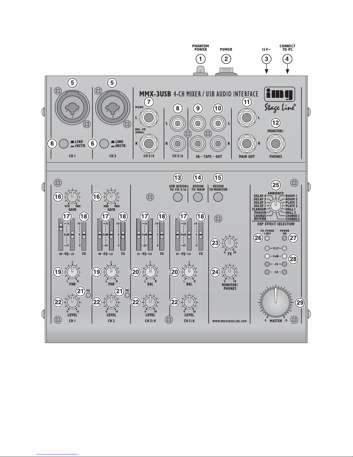
1) Als Grundeinstellung vorerst
– alle Regler GAIN (16), EQ (17), PAN (19) und
BAL (20) sowie den Regler MASTER (29) in die
Mittelposition stellen
– alle Regler LEVEL (22) und den Effekt-Pegelreg-
ler FX (23) ganz nach links zurückdrehen
– die Taste ASSIGN TO MAIN (14) ausrasten
2) Soll das Eingangssignal der USB-Buchse (4) über
den Kanal CH 5/6 wiedergegeben werden, die Tas-
te USB ASSIGN TO CH 5/6 (13) drücken. Bei ge-
drückter Taste belegen das USB-Eingangssignal
und das Signal des Eingangs CH 5/6 (8) den glei-
chen Kanal. Deshalb den Eingang CH 5/6 nicht ver-
wenden, wenn nur das USB-Eingangssignal wie-
dergegeben werden soll, anderenfalls erhält der
Kanal das Mischsignal beider Quellen.
Hinweis: Beachten Sie bei Aufnahmen über die USB-
Buchse die Gefahr von Rückkopplungen, wenn das Auf-
nahmesignal des Computers als Eingangssignal auf den
Kanal CH 5/6 geschaltet wird.
3) Um einen Mono-Kanal optimal auszusteuern, ein
Tonsignal auf den Kanal geben und seinen Regler
LEVEL (22) bis ca. zur Mitte aufdrehen. Den Regler
GAIN (16) des Kanals so einstellen, dass bei den
lautesten Stellen die 0-dB-LEDs der Pegelanzeige
(28) kurz aufleuchten. Danach die Klangeinstellung
mit den Reglern EQ (17) durchführen: HI für die
Höhen, LO für die Bässe. Da sich Klangeinstellun-
gen auf den Kanalpegel auswirken, die Gain-Ein-
stellung ggf. korrigieren.
Danach den Regler LEVEL wieder ganz zurück-
drehen und die gleichen Einstellungen für den zwei-
ten Mono-Kanal durchführen.
4) Für die Klangeinstellung eines Stereo-Kanals die
Regler LEVEL (22) der übrigen Kanäle ganz zu-
rückdrehen und den Regler LEVEL des betreffen-
den Stereo-Kanals so weit aufdrehen, dass der
Klang mit den Klangreglern (17) optimal eingestellt
werden kann.
5) Sind alle Einstellungen zur Pegelanpassung und
alle Klangeinstellungen durchgeführt, mit den Reg-
lern LEVEL (22) die Signale der Eingangskanäle im
gewünschten Lautstärkeverhältnis mischen. Die
LEDs PK (21) der Mono-Kanäle sollten gar nicht
oder höchstens bei Signalspitzen kurz aufflackern.
Leuchten sie ständig, die Lautstärke des Kanals
reduzieren.
Die Regler LEVEL nicht benutzter Kanäle immer
ganz nach links zurückdrehen.
6) Für die Mono-Kanäle mit den Reglern PAN (19) die
Mono-Signale im Stereo-Klangbild platzieren und
für die Stereo-Kanäle mit den Reglern BAL (20) die
Stereo-Balance einstellen.
7) Um das Signal des Eingangs TAPE IN (9), z. B.
Bandeinspielungen oder CD-Wiedergabe, auf das
Summensignal zu schalten, die Taste ASSIGN TO
MAIN (14) drücken. Soll das TAPE-IN-Signal allein
auf die Summe gegeben werden, die Regler LEVEL
der Eingangskanäle ganz zurückdrehen.
Hinweis: Wird eine über den Ausgang TAPE OUT (10)
laufende Aufnahme zeitgleich über den Eingang TAPE IN
wiedergegeben, darf die Taste ASSIGN TO MAIN nicht
gedrückt sein, da sonst eine Rückkopplung auftritt.
8) Mit dem Regler MASTER (29) die gewünschte Ge-
samtlautstärke einstellen. Dabei die Pegelanzeige
(28) beachten. In der Regel wird bei 0 dB eine opti-
male Aussteuerung erreicht. Ist der Ausgangspegel
WARNUNG Stellen Sie die Lautstärke der Audio-
anlage und des Kopfhörers nie sehr
hoch ein. Hohe Lautstärken können auf
Dauer das Gehör schädigen! Das Ohr
gewöhnt sich an hohe Lautstärken und
empfindet sie nach einiger Zeit als nicht
mehr so hoch. Erhöhen Sie darum eine
hohe Lautstärke nach der Gewöhnung
nicht weiter.
6
CH
D
A

7
des Mischpults jedoch für das nachfolgende Gerät
zu hoch, muss das Summensignal entsprechend
niedriger eingestellt werden. Leuchten die roten
Übersteuerungsanzeigen CLIP, den Masterregler
und/oder einzelne Kanal-Pegelregler entsprechend
zurückdrehen.
5.2 Effekt zumischen
1) Den Effekt-Pegelregler FX (23) bis ca. zur Mitte auf-
drehen, so dass die nachfolgenden Effekteinstel-
lungen zu hören sind.
2) Mit dem Drehschalter DSP EFFECT SELECTION
(25) einen von den 16 verfügbaren Effekten aus-
wählen.
3) Mit den Schiebereglern FX (18) für jeden Kanal den
gewünschten Effektanteil einstellen.
4) Mit dem Effekt-Pegelregler FX (23) das Effektsignal
in der gewünschten Intensität auf die Signalsumme
mischen.
5.3 Abhören über Kopfhörer
Die Lautstärke für den Kopfhörer mit dem Regler
MONITOR/PHONES (24) einstellen und mit der Taste
ASSIGN TO MONITOR (15) das Abhörsignal für den
Kopfhörer wählen:
– Um das, vom Regler MASTER (29) unbeeinflusste,
Summensignal abzuhören, muss die Taste ausge-
rastet sein.
– Um das Eingangssignal der Buchsen TAPE IN (9)
abzuhören, muss die Taste gedrückt sein.
6 Technische Daten
Eingangsempfindlichkeit/
Impedanz
CH 1, CH 2, XLR: . . . . 1 mV/2,2 kΩ
CH 1, CH 2, Klinke: . . . 5 mV/20 kΩ (LINE)
5 mV/150 kΩ (INSTR.)
CH 3/4: . . . . . . . . . . . . 360 mV/22 kΩ
CH 5/6: . . . . . . . . . . . . 600 mV/34 kΩ
TAPE IN: . . . . . . . . . . . 100 mV/23 kΩ
Ausgangspegel
MAIN OUT, TAPE OUT: 1,1 V (bei Anzeige 0 dB),
max. 6,5 V
MONITOR/PHONES: . max. 6,5 V
Frequenzbereich: . . . . . . 20 – 20 000 Hz
Klirrfaktor: . . . . . . . . . . . . < 0,1 %
Klangregler
Tiefen: . . . . . . . . . . . . . ±15 dB/80 Hz
Höhen: . . . . . . . . . . . . ±15 dB/12 kHz
Kopfhörerimpedanz: . . . . ≥ 8 Ω
USB-Schnittstelle: . . . . . . USB1.1 kompatibel,
Abtastrate max. 48 kHz,
Latenz (A/D-Wandlung)
0,4 ms bei 44,1 kHz
Phantomspeisung für
XLR-Anschlüsse: . . . . . . +48 V (schaltbar)
Stromversorgung: . . . . . . über beiliegendes Netz-
gerät an 230 V~/50 Hz
Einsatztemperatur: . . . . . 0 – 40 °C
Abmessungen: . . . . . . . . 185 × 47 × 195 mm
Gewicht: . . . . . . . . . . . . . 1,1 kg
Geeignete Betriebssysteme
für USB-Betrieb: . . . . . . . Windows 98 SE,
Windows ME,
Windows 2000,
Windows XP,
Windows Vista,
Windows 7,
Mac OS 9.1, Mac OS X
Windows ist ein registriertes Warenzeichen der Microsoft Corporation
in den USA und anderen Ländern.
Mac OS ist ein registriertes Warenzeichen von Apple Computer, Inc.
in den USA und anderen Ländern.
Änderungen vorbehalten.
CH
A
D
Diese Bedienungsanleitung ist urheberrechtlich für MONACOR ®INTERNATIONAL GmbH & Co. KG geschützt.
Eine Reproduktion für eigene kommerzielle Zwecke – auch auszugsweise – ist untersagt.

All operating elements and connections described
can be found on page 2.
1 Operating Elements and Connections
1On/off switch of the phantom power (+48 V) for the
XLR jacks (5) of channels CH 1 and CH 2
also see warning notes in chapter 4
2POWER switch of the mixer
3Power supply jack for connection of the power sup-
ply unit provided
4USB jack (type B) for connection to a computer: it
can be used both as an audio output (output of the
sum signal) and as an audio input (feed-in of audio
data for reproduction via channel CH 5/6)
5Mono input (combined jack XLR, bal./6.3 mm jack,
unbal.) for channel CH 1 and channel CH 2, for
connection of a microphone via an XLR plug or an
audio source with line signal level via a 6.3 mm plug
6Impedance switch, for channel CH 1 and channel
CH 2: press the button when an electric guitar or an
electric bass with passive audio pick-up has been
connected to the 6.3 mm jack (5)
7Stereo input (6.3 mm jack, bal.) for channel CH 3/4
for connection of an audio source with line signal
level; when connecting a mono source, use jack L
only.
8Stereo input (RCA) for channel CH 5/6 for connec-
tion of an audio source with line signal level
9Stereo input (RCA) for connection to the output of
a recorder
10 Stereo output (RCA) for connection to the input of
a recorder
11 Stereo output (6.3 mm jack, unbal.) for connection
of an amplifier or another unit, e. g. a second mixer
12 Output (6.3 mm jack) for connection of stereo
headphones (minimum impedance 8 Ω) for moni-
toring the sum signal [independent of the master
control (29)] or the signal at the input TAPE IN (9)
13 Button to switch the input signal of the USB jack (4)
to channel CH 5/6
14 Button to switch the signal of the input TAPE IN (9)
to the sum signal
15 Button to switch the signal of the input TAPE IN (9)
to the headphone output (12)
16 Control to adjust the input amplification, for channel
CH 1 and channel CH 2
17 Equalizer to adjust the high frequencies (HI) and
low frequencies (LO), for each input channel
18 Effect control, for each input channel, to adjust the
effect component for each channel
19 Panorama control, for channel CH 1 and channel
CH 2, to place the mono signal in the stereo sound
20 Balance control, for channel CH 3/4 and channel
CH 5/6
21 Level peak indication, for channel CH 1 and chan-
nel CH 2
22 Level control, for each input channel
23 Effect level control to add the effect signal to the
sum signal
24 Volume control for the headphone output (12)
25 Rotary switch to select the effect
26 Control indication for the phantom power
also see item (1)
27 POWER ON indication
28 Stereo level indication for the sum signal adjusted
with the master control (29); in case of overload the
CLIP LEDs light up
29 Overall level control (master control): defines the
level of the sum signal sent via the outputs MAIN
OUT (11), TAPE OUT (10) and the USB jack (4)
2 Safety Notes
The units (mixer and plug-in power supply unit) corre-
spond to all relevant directives of the EU and are there-
fore marked with .
It is essential to observe the following items:
GThe units are suitable for indoor use only. Protect
them against dripping water and splash water, high
air humidity, and heat (admissible ambient tempera-
ture range 0 – 40 °C).
GDo not place any vessels filled with liquid, e. g. drink-
ing glasses, on the units.
GThe heat being generated in the mixer must be car-
ried off by air circulation. Therefore, the air vents at
the housing must not be covered.
GDo not set the mixer into operation, and immediately
disconnect the power supply unit from the mains
socket if
1. there is visible damage to the mixer or the power
supply unit,
2. a defect might have occurred after a drop or simi-
lar accident,
3. malfunctions occur.
The units must in any case be repaired by skilled
personnel.
GFor cleaning only use a dry, soft cloth, never use
chemicals or water.
GNo guarantee claims for the units and no liability for
any resulting personal damage or material damage
will be accepted if the units are used for other pur-
poses than originally intended, if they are not cor-
WARNING The power supply unit is supplied with
hazardous mains voltage. Leave serv-
icing to skilled personnel only. Inexpert
handling or modification of the power
supply unit may cause an electric shock
hazard.
8
GB

rectly connected or operated, or not repaired in an
expert way.
3 Applications
This miniature audio mixer with USB interface and
DSP effect unit is suitable for universal applications,
e. g. for audio recording at the computer. It has four
input channels, i. e. 2 × mono, 2 × stereo, for connect-
ing microphones (also phantom-powered) and audio
sources with line signal level (e. g. musical instru-
ments, players). In addition, connections for a recorder
and headphones are provided. The mixed stereo sig-
nal is sent via 6.3 mm jacks and the USB jack. The
USB jack can be used at the same time as an input for
transferring audio data from the computer to the mixer.
The power supply is made via the supplied AC
power supply unit.
4 Setting into Operation
Prior to connection/disconnection and prior to each
switching on, the output controls MONITOR/PHONES
(24) and MASTER (29) should be turned back to “0”.
1) As audio sources, microphones and/or audio
sources with line signal level (e. g. effect units,
musical instruments, players) can be connected to
the four input channels.
Mono channels CH 1 and CH 2:
Combined XLR/6.3 mm jacks are available as
inputs (5).
– Connect microphones to the balanced XLR jacks.
For phantom-powered microphones it is possible
to activate a 48 V phantom power for both XLR
jacks together with the switch PHANTOM
POWER (1). When activated (switch position I
= on), the indication PH.POWER +48V (26) lights
up during operation.
– Connect mono sources with line level to the un-
balanced 6.3 mm jacks. It is also possible to di-
rectly connect musical instruments of high im-
pedance (electric guitar, electric bass) to these
jacks: in this case press the button for impedance
switching (6) for the channel.
– Stereo channels CH 3/4 and CH 5/6:
Stereo sources with line level may be connected
to the 6.3 mm jacks (7) of channel CH 3/4 and to
the RCA jacks (8) of channel CH 5/6 (L = left
channel, R = right channel). The jacks of channel
CH 3/4 are balanced, however, it is also possible
to connect units with unbalanced output via two-
pole plugs. For connecting a mono unit to chan-
nel CH 3/4, use jack L only: Then the mono sig-
nal is internally sent to the right channel and the
left channel.
2) The RCA jacks TAPE can be used for connection of
a stereo recorder:
– Connect the replay output of the recorder to the
input TAPE IN (9).
– Connect the recording input of the recorder to the
output TAPE OUT (10); the output receives the
sum signal adjusted with the control MASTER
(29).
However, the connections may also be used for
other units with line signal level, e. g. a reproducer
like CD player or MP3 player may be connected to
TAPE IN or an amplifier to TAPE OUT.
3) Connect stereo headphones (impedance ≥ 8 Ω) to
the 6.3 mm jack MONITOR/PHONES (12).
4) The sum signal adjusted with the control MASTER
(29) is present at the stereo output MAIN OUT (11).
Here e. g. an amplifier or a second mixer may be
connected. The 6.3 mm jacks are unbalanced.
5) For power supply connect the power supply unit
provided to the jack 15 V~ (3) and to a mains socket
(230 V~/50 Hz).
Note: If the mixer is not used for a longer time, disconnect
the power supply unit from the socket. Even when the
mixer is switched off, the power supply unit has a low
power consumption.
6) To switch on the mixer, set the POWER switch (2)
to position I. The power indication POWER ON (27)
lights up.
4.1 Operation with a computer
For operation of the mixer with a computer use the
audio software supplied with the operating system or
an audio software installed additionally. Various audio
programmes for recording and reproduction are avail-
able free of charge on the Internet.
1) Boot up the computer and connect the USB jack (4)
to a USB port at the computer via the USB cable
provided. The USB interface of the mixer is recog-
nized by the computer as an external unit for audio
input and audio output, depending on the operating
system e. g. as “USB Audio CODEC”. The required
drivers (standard drivers of the operating system)
are available on the computer.
Note: If not all drivers required are on the computer, they
have to be installed, e. g. via the original CD of the oper-
ating system. If necessary, restart the computer after
installation.
Caution! With the phantom power activated,
no microphone with unbalanced output must
be connected as it may be damaged.
To prevent switching noise, only activate or
deactivate the phantom power when the mixer
is switched off or the output controls are set
to “0”.
If the units are to be put out of operation
definitively, take them to a local recycling
plant for a disposal which is not harmful to the
environment.
9
GB

2) Activate the audio program used and make the
necessary adjustments for the audio reproduction
via the mixer or audio recording from the mixer
(instructions of the program). The mixer can be
operated according to chapter 5.
If no audio recording or audio reproduction is possible,
check in the system settings of the computer if the
USB interface has been selected for the audio input or
audio output.
Hint: If the mixer is connected both to a computer and to
units which are earthed via their mains cable (e. g. amplifier),
ground loops may occur due to hum interference. To elimi-
nate them, the mixer can be connected to the respective unit
via a ground isolator (e. g. FGA-102 or FGA-202 from the
product range of “img Stage Line”).
5 Operation
5.1 Mixing audio sources
The following steps merely serve as an aid, other ways
of procedure are also possible.
1) As a basic setting first
– set all controls GAIN (16), EQ (17), PAN (19) and
BAL (20) and the control MASTER (29) to mid-
position.
– turn all controls LEVEL (22) and the effect level
control FX (23) back to the left stop
– disengage the button ASSIGN TO MAIN (14)
2) To reproduce the input signal of the USB jack (4) via
channel CH 5/6, press the button USB ASSIGN TO
CH 5/6 (13). With the button pressed the USB input
signal and the signal of the input CH 5/6 (8) use the
same channel. Therefore, do not use input CH 5/6
to reproduce the USB input signal only, otherwise
the channel receives the mixed signal of both
sources.
Note: Please pay attention to the hazard of feedback if
recordings are made via the USB jack, when the record-
ing signal of the computer is switched as an input signal
to channel CH 5/6.
3) To adjust a mono channel to an optimum level, feed
an audio signal to the channel and turn up its con-
trol LEVEL (22) approximately to mid-position.
Adjust the control GAIN (16) of the channel so that
the 0 dB LEDs of the level indication shortly light up
at passages of highest volume. Then adjust the
sound with the controls EQ (17): HI for the high fre-
quencies, LO for the bass frequencies. As the
sound adjustments affect the channel level, read-
just the gain adjustment, if necessary.
Then turn the control LEVEL back to the stop
and make the same adjustments for the second
mono channel.
4) For the sound adjustment of a stereo channel turn
the controls LEVEL (22) of the remaining channels
back to the stop and turn up the control LEVEL of
the respective stereo channel so that the sound can
be adjusted in an optimum way with the equalizer
controls (17).
5) When all adjustments for level matching and all
sound adjustments have been made, mix the sig-
nals of the input channels in the desired volume
ratio with the controls LEVEL (22). The LEDs PK
(21) of the mono channels should not flicker at all or
only flicker shortly at signal peaks. If they light up
permanently, attenuate the volume of the channel.
Always turn the controls LEVEL of the channels
not used back to the left stop.
6) For the mono channels place the mono signals in
the stereo sound with the controls PAN (19) and
adjust the stereo balance for the stereo channels
with the controls BAL (20).
7) To switch the signal of the input TAPE IN (9), e. g.
reproductions of tape or CD, to the sum signal,
press the button ASSIGN TO MAIN (14). To feed
the TAPE IN signal only to the sum, turn the controls
LEVEL of the input channels back to the stop.
Note: If a recording made via the output TAPE OUT (10)
is reproduced via the input TAPE IN at the same time, the
button ASSIGN TO MAIN must not be pressed as other-
wise feedback will occur.
8) Adjust the desired overall volume with the control
MASTER (29). Then observe the level indication
(28). In general, an optimum control is obtained at
0 dB. However, if the output level of the mixer is too
high for the following unit, the sum signal must be
adjusted to a correspondingly lower level. If the red
overload LEDs CLIP light up, turn back the master
control and/or individual channel level controls
accordingly.
WARNING Never adjust the audio system and the
headphones to a very high volume.
Permanent high volumes may damage
your hearing! Your ear will get accus-
tomed to high volumes which do not
seem to be that high after some time.
Therefore, do not further increase a
high volume after getting used to it.
10
GB

5.2 Adding an effect
1) Turn up the effect level control FX (23) approxi-
mately to mid-position so that the following effect
adjustments can be heard.
2) Select one of 16 effects available with the rotary
switch DSP EFFECT SELECTION (25).
3) Adjust the desired effect component for each chan-
nel with the sliding controls FX (18).
4) Add the effect signal in the desired intensity to the
signal sum with the effect level control FX (23).
5.3 Monitoring via headphones
Adjust the volume for the headphones with the control
MONITOR/PHONES (24) and select the monitoring
signal for the headphones with the button ASSIGN TO
MONITOR (15):
– To monitor the sum signal not affected by the control
MASTER (29), the button must be disengaged.
– To monitor the input signal of the jacks TAPE IN (9),
the button must be pressed.
6 Specifications
Input sensitivity/
Impedance
CH 1, CH 2, XLR: . . . . 1 mV/2.2 kΩ
CH 1, CH 2, jack . . . . . 5 mV/20 kΩ (LINE)
5 mV/150 kΩ (INSTR.)
CH 3/4: . . . . . . . . . . . . 360 mV/22 kΩ
CH 5/6: . . . . . . . . . . . . 600 mV/34 kΩ
TAPE IN: . . . . . . . . . . . 100 mV/23 kΩ
Output level
MAIN OUT/TAPE OUT: 1.1 V (at indication 0 dB),
6.5 V max.
MONITOR/PHONES: . 6.5 V max.
Frequency range: . . . . . . 20 – 20 000 Hz
THD: . . . . . . . . . . . . . . . . < 0.1 %
Equalizer
bass range: . . . . . . . . . ±15 dB/80 Hz
high range: . . . . . . . . . ±15 dB/12 kHz
Headphone impedance: . ≥ 8 Ω
USB interface: . . . . . . . . . USB1.1 compatible,
sampling rate 48 kHz max.,
latency (A/D conversion)
0.4 ms at 44,1 kHz
Phantom power for
XLR connections: . . . . . . +48 V (switchable)
Power supply: . . . . . . . . . via power supply unit
provided, connected
to 230 V~/50 Hz
Ambient temperature: . . . 0 – 40 °C
Dimensions: . . . . . . . . . . 185 × 47 × 195 mm
Weight: . . . . . . . . . . . . . . 1.1 kg
Suitable operating systems
for USB operation: . . . . . Windows 98 SE,
Windows ME,
Windows 2000,
Windows XP,
Windows Vista,
Windows 7,
Mac OS 9.1, Mac OS X
Windows is a registered trademark of Microsoft Corporation in the USA
and other countries.
Mac OS is a registered trademark of Apple Computer, Inc. in the USA and
other countries.
Subject to technical modifications.
11
GB
All rights reserved by MONACOR ®INTERNATIONAL GmbH & Co. KG. No part of this instruction manual may
be reproduced in any form or by any means for any commercial use.

Vous trouverez sur la page 2 la description des élé-
ments et branchements.
1 Eléments et branchements
1Interrupteur Marche/Arrêt de lʼalimentation fan-
tôme (+48 V) pour les prises XLR (5) des canaux
CH 1 et CH 2, voir également avertissements
dans le chapitre 4
2Interrupteur marche/arrêt de la table de mixage
3Prise alimentation pour brancher le bloc secteur
livré
4Port USB (type B) pour brancher à un ordinateur :
peut également être utilisé comme sortie audio
(sortie du signal master) et comme entrée audio
(insertion de données audio pour lecture via le
canal CH 5/6)
5Entrée mono (prise combinée XLR, sym./jack 6,35,
asym.), pour canal CH 1 et canal CH 2, pour bran-
cher un microphone via une fiche XLR mâle ou une
source audio avec niveau de signal ligne via une
fiche jack mâle
6Commutateur dʼimpédance, pour canal CH 1 et
canal CH 2 ; appuyez sur la touche si une guitare
électrique ou une basse électrique avec capteur de
son passif est branchée à la prise jack (5)
7Entrée stéréo (jack 6,35, sym.) pour canal CH 3/4
pour brancher une source audio avec un niveau de
signal ligne : si vous branchez une source mono,
utilisez uniquement la prise L.
8Entrée stéréo (RCA) pour canal CH 5/6 pour bran-
cher une source audio avec niveau de signal ligne
9Entrée stéréo (RCA) pour brancher à la sortie dʼun
enregistreur
10 Sortie stéréo (RCA) pour brancher à lʼentrée dʼun
enregistreur
11 Sortie stéréo (jack 6,35, asym.) pour brancher un
amplificateur ou un autre appareil, par exemple
une seconde table de mixage
12 Sortie (jack 6,35) pour brancher un casque stéréo
(impédance minimale 8 Ω) pour écouter le signal
master [indépendamment du réglage MASTER
(29)] ou le signal présent à lʼentrée TAPE IN (9)
13 Touche pour commuter le signal dʼentrée de la
prise USB (4) sur canal CH 5/6
14 Touche pour commuter le signal de lʼentrée TAPE
IN (9) sur le signal master
15 Touche pour commuter le signal de lʼentrée TAPE
IN (9) sur la sortie casque (12)
16 Réglage pour régler lʼamplification dʼentrée, pour
canal CH 1 et canal CH 2
17 Egaliseur pour régler les aigus (HI) et les graves
(LO), pour chaque canal dʼentrée
18 Réglage dʼeffet, pour chaque canal dʼentrée, pour
régler la part dʼeffet par canal
19 Réglage de panoramique, pour canal CH 1 et canal
CH 2, pour placer le signal mono dans lʼimage stéréo
20 Réglage de balance, pour canal CH 3/4 et canal
CH 5/6
21 LED témoin dʼécrêtage pour canal CH 1 et canal
CH 2
22 Réglage de niveau pour chaque canal dʼentrée
23 Réglage de niveau dʼeffet pour mixer le signal
dʼeffet sur le signal master
24 Réglage de volume pour la sortie casque (12)
25 Sélecteur rotatif de lʼeffet
26 LED de contrôle pour lʼalimentation fantôme,
voir également position (1)
27 Témoin de fonctionnement
28 VU-mètre stéréo pour le signal master réglé avec le
réglage MASTER (29) ; en cas de surcharge, les
LEDs CLIP brillent.
29 Réglage de niveau général (réglage MASTER) ;
définit le niveau du signal master émis via les
sorties MAIN OUT (11), TAPE OUT (10) et le port
USB (4)
2 Conseils dʼutilisation et de sécurité
Les appareils (table de mixage et bloc secteur) répon-
dent à toutes les directives nécessaires de lʼUnion
européenne et portent donc le symbole .
Respectez scrupuleusement les points suivants :
GLes appareils ne sont conçus que pour une utilisa-
tion en intérieur. Protégez-les des éclaboussures,
de tout type de projections dʼeau, dʼune humidité
dʼair élevée et de la chaleur (température ambiante
admissible 0 – 40 °C).
GEn aucun cas, vous ne devez pas poser dʼobjet
contenant du liquide ou un verre sur les appareils.
GLa chaleur dégagée dans la table de mixage doit
être correctement évacuée par une circulation cor-
recte de lʼair. En aucun cas, les ouïes de ventilation
ne doivent être obturées.
GNe faites pas fonctionner la table de mixage et
débranchez le bloc secteur immédiatement dans les
cas suivants :
1. la table de mixage ou le bloc secteur présente des
dommages visibles.
2. après une chute ou accident similaire, vous avez
un doute sur lʼétat de lʼappareil.
AVERTISSEMENT Le bloc secteur est alimenté par une
tension dangereuse. Ne touchez
jamais lʼintérieur de lʼappareil car,
en cas de mauvaise manipulation,
vous pouvez subir une décharge
électrique.
12
F
B
CH

3. des dysfonctionnements apparaissent.
Dans tous les cas, les dommages doivent être répa-
rés par un technicien spécialisé.
GPour le nettoyage, utilisez un chiffon sec et doux, en
aucun cas de produits chimiques ou dʼeau.
GNous déclinons toute responsabilité en cas de dom-
mages corporels ou matériels résultants si les appa-
reils sont utilisés dans un but autre que celui pour
lequel ils ont été conçus, sʼils ne sont pas correcte-
ment branchés ou utilisés ou sʼils ne sont pas répa-
rés par une personne habilitée ; en outre, la garan-
tie deviendrait caduque.
3 Possibilités dʼutilisation
Cette table de mixage audio miniature avec interface
USB et unité dʼeffets DSP est prévue pour une utilisa-
tion universelle, par exemple prise de son sur lʼordina-
teur. Elle dispose de quatre canaux dʼentrée – 2 ×
mono, 2 × stéréo – pour brancher des microphones
(alimentés également par une alimentation fantôme)
et des sources audio avec niveau de signal ligne (par
exemple instruments, lecteurs). Des branchements
pour un enregistreur et un casque sont également pré-
vus. Le signal de mixage stéréo est diffusé via les
prises jack 6,35 et le port USB. Le port USB peut éga-
lement être utilisé simultanément comme entrée pour
transmettre des données audio de lʼordinateur vers la
table de mixage.
Lʼalimentation sʼeffectue via le bloc secteur tension
alternative livré.
4 Fonctionnement
Avant dʼeffectuer les branchements ou de les séparer,
avant chaque mise en service, il faut mettre les ré-
glages de sortie MONITOR/PHONES (24) et MASTER
(29) sur “0”.
1) Comme sources audio, on peut relier des micro-
phones et/ou sources audio avec niveau de signal
ligne (par exemple appareils à effets, instruments
de musique, lecteurs) aux quatre canaux dʼentrée.
canaux mono CH 1 et CH 2 :
prises combinées XLR/jack 6,35 comme entrées
(5)
– Reliez les microphones aux prises XLR. Elles
sont branchées en symétrique. Pour des micro-
phones à alimentation fantôme, on peut allumer
pour les deux prises XLR ensemble une alimen-
tation fantôme 48 V avec lʼinterrupteur PHAN-
TOM POWER (1). Lorsquʼelle est allumée (posi-
tion interrupteur I= marche), la LED PH.POWER
+48V (26) brille pendant le fonctionnement.
– Reliez les sources mono avec niveau ligne aux
prises jack. Elles sont branchées en asymé-
trique. On peut également relier directement à
ces prises des instruments haute impédance
(guitare électrique, basse électrique) : dans ce
cas, appuyez pour le canal, sur la touche de
commutation dʼimpédance (6).
Canaux stéréo CH 3/4 et CH 5/6 :
On peut relier aux prises jack 6,35 (7) du canal
CH 3/4 et aux prises RCA (8) du canal CH 5/6 des
sources stéréo avec niveau ligne (L = canal gauche,
R = canal droit). Les prises du canal CH 3/4 sont
branchées en symétrique, on peut également bran-
cher des appareils avec sortie asymétrique via des
fiches jack 2 pôles. Si vous souhaitez brancher un
appareil mono au canal CH 3/4, utilisez uniquement
la prise L : le signal mono est commuté ensuite en
interne sur le canal gauche et le canal droit.
2) Les prises RCA TAPE peuvent être utilisées pour
brancher un enregistreur stéréo :
– Reliez la sortie lecture de lʼenregistreur à lʼentrée
TAPE IN (9).
– Reliez lʼentrée enregistrement de lʼenregistreur à
la prise TAPE OUT (10) ; la sortie reçoit le signal
master réglé avec le réglage MASTER (29).
Les branchements peuvent être utilisés pour dʼau-
tres appareils avec niveau de signal ligne, par
exemple, on peut brancher un lecteur tel que lec-
teur CD ou MP3 à TAPE IN ou un amplificateur à
TAPE OUT.
3) On peut relier un casque stéréo (impédance ≥ 8 Ω)
à la prise jack 6,35 MONITOR/PHONES (12).
4) Le signal master réglé avec le réglage MASTER
(29) est présent à la sortie stéréo MAIN OUT (11).
On peut brancher ici un amplificateur ou une
seconde table de mixage. Les prises jack 6,35 sont
branchées en asymétrique.
5) Pour lʼalimentation, reliez le bloc secteur livré à la
prise 15 V~ (3) et à une prise secteur 230 V~/50 Hz.
Conseil : en cas de non utilisation prolongée de la table
de mixage, débranchez le bloc secteur de la prise car,
même si la table de mixage est éteinte, le bloc secteur a
une faible consommation.
6) Pour allumer la table de mixage, mettez lʼinterrup-
teur POWER (2) sur la position I. La LED POWER
ON, témoin de fonctionnement (27) brille.
Attention ! Lorsque lʼalimentation fantôme est
activée, il ne faut pas brancher de microphone
à sortie asymétrique, il peut être endommagé.
Pour éviter tout bruit fort de commutation, allu-
mez ou éteignez lʼalimentation fantôme unique-
ment lorsque la table de mixage est éteinte ou
si les réglages des sorties sont tournés sur “0”.
Lorsque les appareils sont définitivement reti-
rés du service, vous devez les déposer dans
une usine de recyclage de proximité pour
contribuer à leur élimination non polluante.
13
F
B
CH

4.1 Fonctionnement avec un ordinateur
Pour faire fonctionner la table de mixage avec un ordi-
nateur, on peut utiliser le logiciel audio livré avec le
système dʼexploitation ou un logiciel audio installé en
plus. Différents programmes audio pour lʼenregistre-
ment et la lecture sont disponibles gratuitement sur
Internet.
1) Faites monter lʼordinateur et reliez le port USB (4)
via le cordon USB livré à un port USB de lʼordina-
teur. Lʼinterface USB de la table de mixage est
reconnu par lʼordinateur comme appareil externe
pour lʼentrée et la sortie audio, selon le système
dʼexploitation, par exemple comme “USB Audio
CODEC”. Les drivers nécessaires (driver standard
du système dʼexploitation) sont prévus sur lʼordina-
teur.
Conseil : Si tous les drivers nécessaires ne sont pas pré-
sents sur lʼordinateur, vous devez les installer, par exem-
ple via le CD dʼorigine du système dʼexploitation. Si
besoin, redémarrez lʼordinateur après lʼinstallation.
2) Appelez le programme audio utilisé et effectuez les
réglages nécessaires pour la lecture audio via la
table de mixage ou les enregistrements audio
depuis la table de mixage (notice du pro-
gramme). La table de mixage peut être utilisée
selon le chapitre 5.
Sʼil nʼy a pas dʼenregistrement audio ou de lecture
audio, vérifiez dans les réglages système de lʼordina-
teur si lʼinterface USB est sélectionné pour lʼentrée
audio ou la sortie audio.
Remarque : si la table de mixage est reliée à un ordinateur
et à des appareils mis à la terre (par exemple amplificateur)
via leur cordon secteur, des ronflements causés par des bou-
clages de masse peuvent se produire. Pour les supprimer,
on peut relier la table de mixage à lʼappareil correspondant
via un filtre séparateur galvanique (par exemple FGA-102 ou
FGA-202 de “img Stage Line”).
5 Utilisation
5.1 Mixage des sources audio
Les points suivants servent dʼaide, dʼautres méthodes
existent.
1) Effectuez tout dʼabord les réglages de base
– mettez tous les réglages GAIN (16), EQ (17),
PAN (19) et BAL (20) et le réglage MASTER (29)
sur la position médiane.
– tournez complètement vers la gauche tous les
réglages LEVEL (22) et le réglage de niveau
dʼeffet FX (23).
– désenclenchez la touche ASSIGN TO MAIN (14)
2) Si le signal dʼentrée du port USB (4) doit être resti-
tué via le canal CH 5/6, appuyez sur la touche USB
ASSIGN TO CH 5/6 (13). Lorsque la touche est
enfoncée, le signal dʼentrée USB et le signal de
lʼentrée CH 5/6 (8) utilisent le même canal. Cʼest
pourquoi nʼutilisez pas lʼentrée CH 5/6 si seul le
signal dʼentrée USB doit être restitué, sinon le canal
reçoit le signal de mixage des deux sources.
Conseil : lors dʼenregistrements via le port USB, faites
attention au risque de larsen si le signal dʼenregistrement
de lʼordinateur doit être commuté comme signal dʼentrée
sur le canal CH 5/6.
3) Pour gérer de manière optimale un canal mono,
appliquez un signal audio sur le canal et tournez son
réglage LEVEL (22) à la moitié environ. Réglez le
réglage GAIN (16) du canal de telle sorte que pour
des passages les plus forts, les LEDs 0 dB du VU-
mètre (28) brillent brièvement. Ensuite effectuez les
réglages de tonalité avec les réglages EQ (17) : HI
pour les aigus, LO pour les graves. Dans la mesure
où les réglages de tonalité influent sur le niveau du
canal, corrigez si besoin le réglage de gain.
Ensuite, tournez le réglage LEVEL complète-
ment dans lʼautre sens et effectuez les mêmes
réglages pour le second canal mono.
4) Pour le réglage de tonalité dʼun canal stéréo, tournez
les réglages LEVEL (22) des canaux restants com-
plètement à gauche, tournez le réglage LEVEL du
canal stéréo concerné jusquʼà ce que la tonalité soit
réglée de manière optimale avec les égaliseurs (17).
5) Lorsque tous les réglages pour lʼadaptation de
niveau et les réglages de tonalité sont effectués,
mixez avec les réglages LEVEL (22) les signaux
des canaux dʼentrée dans le rapport de volume
souhaité. Les LEDs PK (21) des canaux mono ne
devraient pas briller brièvement ou au pire que briè-
vement pour des pointes de signal. Si elles brillent
en continu, diminuez le volume du canal.
Tournez vers la gauche entièrement les réglages
LEVEL des canaux inutilisés.
6) Pour les canaux mono, placez avec les réglages
PAN (19), les signaux mono dans lʼimage sonore
stéréo et la balance stéréo pour les canaux stéréo
avec les réglages BAL (20).
7) Pour commuter le signal de lʼentrée TAPE IN (9),
par exemple lectures de bande ou restitution de
CD, sur le signal master, appuyez sur la touche
ASSIGN TO MAIN (14). Si seul le signal TAPE IN
doit être appliqué sur le master, tournez les
réglages LEVEL des canaux dʼentrées entièrement
à gauche.
Conseil : si un enregistrement effectué via la sortie TAPE
OUT (10) est simultanément restitué via lʼentrée TAPE
IN, la touche ASSIGN TO MAIN ne doit pas être enfon-
cée, sinon il y a risque de larsen.
AVERTISSEMENT Ne réglez pas le volume de lʼinstal-
lation audio et du casque trop fort.
Un volume trop élevé peut, à long
terme, générer des troubles de lʼau-
dition. Lʼoreille humaine sʼhabitue à
des volumes élevés et ne les perçoit
plus comme tels au bout dʼun cer-
tain temps. Nous vous conseillons
donc de régler le volume et de ne
plus le modifier.
14
F
B
CH

8) Avec le réglage MASTER (29), réglez le volume
général souhaité. Faites attention aux indications
du VU-mètre (28). En règle générale, pour 0 dB, on
a un réglage optimal. Cependant, si le niveau de
sortie de la table de mixage est trop fort pour lʼap-
pareil suivant, diminuez en conséquence le signal
master. Si les LEDs rouges CLIP, témoins dʼécrê-
tage, brillent, tournez le réglage MASTER et/ou les
réglages de canal vers la gauche en conséquence.
5.2 Mixage de lʼeffet
1) Tournez le réglage de niveau de lʼeffet FX (23) à la
moitié environ pour que les réglages dʼeffets sui-
vants soient audibles.
2) Avec le réglage DSP EFFECT SELECTION (25),
sélectionnez un des 16 effets disponibles.
3) Avec les réglages à glissières FX (18), réglez pour
chaque canal la part dʼeffet souhaitée.
4) Avec le réglage de niveau dʼeffet FX (23), mixez le
signal dʼeffet dans lʼintensité souhaitée sur le signal
master.
5.3 Ecoute via un casque
Réglez le volume pour le casque avec le réglage
MONITOR/PHONES (24), et avec la touche ASSIGN
TO MONITOR (15), sélectionnez le signal pour écou-
ter le casque :
– pour écouter le signal master non influencé par le
réglage MASTER (29), la touche ne doit pas être
enclenchée.
– pour écouter le signal dʼentrée des prises TAPE IN
(9), la touche doit être enfoncée.
6 Caractéristiques techniques
Sensibilité dʼentrée/
impédance
CH 1, CH 2, XLR : . . . . 1 mV/2,2 kΩ
CH 1, CH 2, jack : . . . . 5 mV/20 kΩ (LINE)
5 mV/150 kΩ (INSTR.)
CH 3/4 : . . . . . . . . . . . . 360 mV/22 kΩ
CH 5/6 . . . . . . . . . . . . . 600 mV/34 kΩ
TAPE IN : . . . . . . . . . . 100 mV/23 kΩ
Niveau de sortie
MAIN OUT, TAPE OUT :
1,1 V (pour affichage
0 dB), max. 6,5 V
MONITOR/PHONES : max. 6,5 V
Bande passante : . . . . . . 20 – 20 000 Hz
Taux de distorsion : . . . . . < 0,1 %
Egaliseur
Graves : . . . . . . . . . . . ±15 dB/80 Hz
Aigus : . . . . . . . . . . . . . ±15 dB/12 kHz
Impédance casque : . . . . ≥ 8 Ω
Interface USB : . . . . . . . . compatible USB1.1 ;
Taux échantillonnage
48 kHz max.,
Latence (conversion A/D)
0,4 ms à 44,1 kHz
Alimentation fantôme
pour connexions XLR : . . +48 V (commutable)
Alimentation : . . . . . . . . . par bloc secteur livré relié
à 230 V~/50 Hz
Température fonc. : . . . . . 0 – 40 °C
Dimensions : . . . . . . . . . . 185 × 47 × 195 mm
Poids : . . . . . . . . . . . . . . . 1,1 kg
Systèmes dʼexploitation
adaptés pour
fonctionnement USB : . . . Windows 98 SE,
Windows ME,
Windows 2000,
Windows XP,
Windows Vista,
Windows 7,
Mac OS 9.1, Mac OS X
Windows est une marque déposée de Microsoft Corporation aux Etats-
Unis et dans les autres pays.
Mac OS est une marque déposée de Apple Computer, Inc. aux Etats-Unis
et dans les autres pays.
Tout droit de modification réservé.
15
F
B
CH
Notice dʼutilisation protégée par le copyright de MONACOR ®INTERNATIONAL GmbH & Co. KG. Toute repro-
duction même partielle à des fins commerciales est interdite.

A pagina 2 si trovano tutti gli elementi di comando
e i collegamenti.
1 Elementi di comando e collegamenti
1Interruttore on/off dellʼalimentazione phantom
(+48 V) per le prese XLR (5) dei canali CH 1 e CH 2
vedi anche gli avvertimenti in capitolo 4
2Interruttore on/off del mixer
3Presa dʼalimentazione per il collegamento dellʼali-
mentatore in dotazione
4Presa USB (tipo B) per il collegamento con un com-
puter: può essere usata come uscita audio (per il
segnale delle somme), ma anche come ingresso
audio (alimentazione di dati audio per la riprodu-
zione mediante il canale CH 5/6)
5Ingresso mono (presa combinata XLR, bil./jack
6,3 mm, sbil.), per i canali CH 1 e CH 2, per il colle-
gamento di un microfono tramite un connettore
XLR oppure di una sorgente audio con livello Line
tramite un jack
6Commutatore dʼimpedenza, per i canali CH 1 e
CH 2: premere il tasto se alla presa jack (5) è colle-
gata una chitarra elettrica o un basso elettrico con
pick-up passivo
7Ingresso stereo (jack 6,3 mm, bil.) per i canali
CH 3/4 per il collegamento di una sorgente audio
con livello Line; collegando una sorgente mono,
usare solo la presa L.
8Ingresso stereo (RCA) per i canali CH 5/6 per il col-
legamento di una sorgente audio con livello Line
9Ingresso stereo (RCA) per il collegamento con
lʼuscita di un registratore
10 Uscita stereo (RCA) per il collegamento con lʼin-
gresso di un registratore
11 Ingresso stereo (jack 6,3 mm, sbil.) per il collega-
mento di un amplificatore o di un altro dispositivo,
come p. es. di un secondo mixer
12 Uscita (jack 6,3 mm) per il collegamento di una cuf-
fia stereo (impedenza min. 8 Ω) per ascoltare il
segnale delle somme [indipendentemente dal
regolatore master (29)] o il segnale allʼingresso
TAPE IN (9)
13 Tasto per portare il segnale dʼingresso della presa
USB (4) sui canali CH 5/6
14 Tasto per portare il segnale dellʼingresso TAPE IN
(9) sul segnale delle somme
15 Tasto per portare il segnale dellʼingresso TAPE IN
(9) sullʼuscita per cuffia (12)
16 Regolatore per impostare il guadagno allʼingresso,
per i canali CH 1 e CH 2
17 Regolatori toni per impostare gli alti (HI) e i bassi
(LO), per ogni canale dʼingresso
18 Regolatore effetti, per ogni canale dʼingresso, per
impostare la parte dellʼeffetto per il canale
19 Regolatore pan, per i canali CH 1 e CH 2, per posi-
zionare il segnale mono fra i segnali stereo
20 Regolatore bilanciamento, per i canali CH 3/4 e
CH 5/6
21 Spia per indicare i picchi, per i canali CH 1 CH 2
22 Regolatore livello, per ogni canale dʼingresso
23 Regolatore livello degli effetti, per miscelare il
segnale degli effetti sul segnale delle somme
24 Regolatore volume per lʼuscita cuffia (12)
25 Selettore per selezionare lʼeffetto
26 Spia di controllo per lʼalimentazione phantom
vedi anche posizione (1)
27 Spia di funzionamento
28 Indicazione del livello stereo per il segnale delle
somme impostato con il regolatore master (29); in
caso di sovrapilotaggio si accendono i LED CLIP
29 Regolatore del livello globale (regolatore master):
determina il livello del segnale delle somme
emesso tramite le uscite MAIN OUT (11), TAPE
OUT (10) e tramite la presa USB (4)
2 Avvertenze di sicurezza
Gli apparecchi (mixer e alimentatore a spina) sono
conformi a tutte le direttive rilevanti dellʼUE e pertanto
portano la sigla .
Si devono osservare assolutamente anche i seguenti
punti:
GGli apparecchi sono adatti solo per lʼuso allʼinterno di
locali. Proteggerli dallʼacqua gocciolante e dagli
spruzzi dʼacqua, da alta umidità dellʼaria e dal calore
(temperatura dʼimpiego ammessa fra 0 e 40 °C).
GNon depositare sugli apparecchi dei contenitori
riempiti di liquidi, p. es. bicchieri.
GDevʼessere garantita la libera circolazione dellʼaria
per dissipare il calore che viene prodotto allʼinterno
del mixer. Perciò non coprire le fessure dʼaerazione.
GNon mettere in funzione il mixer e staccare subito
lʼalimentatore dalla rete se:
1. il mixer o lʼalimentatore presentano dei danni
visibili;
2. dopo una caduta o dopo eventi simili sussiste il
sospetto di un difetto;
3. lʼapparecchio non funziona correttamente.
Per la riparazione rivolgersi sempre ad unʼofficina
competente.
GPer la pulizia usare solo un panno morbido, asciutto;
non impiegare in nessun caso acqua o prodotti
chimici.
AVVERTIMENTO Lʼalimentatore è alimentato con peri-
colosa tensione di rete. Non interve-
nire mai personalmente al suo
interno. La manipolazione scorretta
può provocare delle scariche elettri-
che pericolose.
16
I

GNel caso dʼuso improprio, di collegamenti sbagliati,
dʼimpiego scorretto o di riparazione non a regola
dʼarte degli apparecchi, non si assume nessuna
responsabilità per eventuali danni consequenziali a
persone o a cose e non si assume nessuna garan-
zia per gli apparecchi.
3 Possibilità dʼimpiego
Questo mixer audio mini con interfaccia USB e unità
DSP per effetti è previsto per usi universali, p. es. per
la registrazione audio sul computer. Dispone di quattro
canali dʼingresso – 2 × mono, 2 × stereo – per il colle-
gamento di microfoni (anche con alimentazione phan-
tom) e di sorgenti audio con livelli Line (p. es. strumenti
musicali, dispositivi di riproduzione). In più sono pre-
senti contatti per un registratore e una cuffia. Il segnale
stereo miscelato viene emesso tramite prese jack
6,3 mm e tramite la presa USB. La presa USB può
essere usata anche come ingresso per la trasmissione
di dati audio dal computer al mixer.
Lʼalimentazione avviene per mezzo dellʼalimenta-
tore a tensione alternata.
4 Messa in funzione
Prima di effettuare/staccare dei collegamenti e prima
di ogni accensione, i regolatori delle uscite MONITOR/
PHONES (24) e MASTER (29) dovrebbero essere
riportati sullo “0”.
1) Come sorgenti audio, ai quattro canali dʼingresso si
possono collegare dei microfoni e/o sorgenti audio
con livello Line (p. es. unità per effetti, strumenti
musicali, dispositivi di riproduzione).
Canali mono CH 1 e CH 2:
Come ingressi (5) sono presenti delle prese combi-
nate XLR/jack 6,3 mm.
– Collegare i microfoni con le prese XLR che sono
cablate in modo bilanciato. Per i microfoni con
alimentazione phantom, con lʼinterruttore PHAN-
TOM POWER (1) si può attivare per entrambe le
prese XLR unʼalimentazione comune di 48 V. Se
tale alimentazione è attivata (posizione dellʼinter-
ruttore I= on), durante il funzionamento è accesa
la spia PH. POWER +48V (26).
– Collegare le sorgenti mono con livello Line con le
prese jack che sono cablate in modo sbilanciato.
A queste prese si possono collegare diretta-
mente anche strumenti musicali ad alta impe-
denza (chitarra elettrica, basso elettrico): in que-
sto caso premere il tasto per la commutazione
dellʼimpedenza (6) del relativo canale.
Canali stereo CH 3/4 e CH 5/6:
Alle prese jack 6,3 mm (7) del canale CH 3/4 e
alle prese RCA (8) del canale CH 5/6 si possono
collegare delle sorgenti stereo con livello Line
(L = canale sinistro, R = canale destro). Le prese
del canale CH 3/4 sono cablate in modo bilanciato,
ma per mezzo di jack a 2 poli si possono collegare
anche apparecchi con uscita sbilanciata. Se al
canale CH 3/4 si deve collegare un apparecchio
mono, usare solo la presa L: il segnale mono pas-
serà internamente sui canali destro e sinistro.
2) Le prese RCA TAPE possono essere sfruttate per il
collegamento di un registratore stereo:
– Collegare lʼuscita di riproduzione del registratore
con lʼingresso TAPE IN (9).
– Collegare lʼingresso di registrazione del registra-
tore con lʼuscita TAPE OUT (10); lʼuscita riceve il
segnale delle somme impostato con il regolatore
MASTER (29).
I contatti possono essere utilizzati anche per altri
apparecchi con livello Line, p. es. è possibile colle-
gare con TAPE IN un dispositivo di riproduzione,
come i lettori CD o MP3, oppure, con TAPE OUT un
amplificatore.
3) Una cuffia stereo (impedenza ≥ 8 Ω) può essere
collegata con la presa jack 6,3 mm MONITOR/
PHONES (12).
4) Allʼuscita stereo MAIN OUT (11) è disponibile il
segnale delle somme impostato con il regolatore
MASTER (29). Qui si può collegare p. es. un ampli-
ficatore o un secondo mixer. Le prese jack 6,3 mm
sono cablate in modo sbilanciato.
5) Per lʼalimentazione collegare lʼalimentatore in dota-
zione con la presa 15 V~ (3) e inserirlo in una presa
di rete (230 V~/50 Hz).
N. B.: Se per un certo periodo non si usa il mixer, stac-
care lʼalimentatore dalla presa di rete perché consuma un
poʼ di corrente anche con il mixer spento.
6) Per accendere il mixer, portare lʼinterruttore POWER
(2) in posizione I. Si accende la spia di funziona-
mento POWER ON (27).
4.1 Funzionamento con un computer
Per il funzionamento del mixer con un computer si può
usare il software audio fornito insieme al sistema ope-
rativo oppure un software audio installato successiva-
mente. Vari programmi audio per riproduzione e regi-
strazione sono disponibili gratuitamente in Internet.
1) Accendere il computer e collegare la presa USB (4)
con una porta USB del computer usando il cavo
Attenzione! Con lʼalimentazione phantom atti-
vata non devʼessere collegato nessun micro-
fono con uscita sbilanciata perché potrebbe
subire dei danni.
Per escludere rumori di commutazione, atti-
vare o disattivare lʼalimentazione phantom solo
con il mixer spento e con i regolatori delle
uscite sullo “0”.
Se si desidera eliminare gli apparecchi defini-
tivamente, consegnarli per lo smaltimento ad
unʼistituzione locale per il riciclaggio.
17
I

USB in dotazione. Lʼinterfaccia USB del mixer
viene riconosciuta dal computer come dispositivo
esterno per lʼinput e per lʼoutput audio, a seconda
del sistema operativo p. es. come “USB Audio
CODEC”. I driver necessari (driver standard del
sistema operativo) sono presenti sul computer.
N. B.: Se non tutti i driver richiesti si trovano sul compu-
ter, occorre installarli successivamente, p. es. tramite il
CD originale del sistema operativo. Eventualmente, dopo
lʼinstallazione riavviare il computer.
2) Aprire il programma audio usato e effettuare le
impostazioni necessarie per la riproduzione audio
tramite il mixer oppure per la registrazione audio dal
mixer (Istruzioni del programma). Quindi, il
mixer può essere comandato come descritto nel
capitolo 5.
Se non avviene nessuna registrazione o riproduzione
audio, controllare nel pannello di controllo del compu-
ter se la porta USB è stata scelta per lʼinput o lʼoutput
audio.
Un consiglio: Se il mixer è collegato sia con un computer
che con degli apparecchi collegati a terra tramite il loro cavo
di rete (p. es. amplificatori), si possono manifestare dei ron-
zii dovuti a un loop di massa. Per eliminare queste interfe-
renze, il mixer può essere collegato con il relativo apparec-
chio per mezzo di un disaccoppiatore di massa (p. es.
FGA-102 o FGA-202 del programma di “img Stage Line”).
5 Funzionamento
5.1 Miscelare le sorgenti audio
Le seguenti indicazioni servono solo come aiuto, dato
che sono possibili anche altri modi di procedere.
1) Per prima cosa, come impostazione base
– portare tutti i regolatori GAIN (16), EQ (17), PAN
(19) e BAL (20) nonché il regolatore MASTER
(29) in posizione centrale
– spostare completamente a sinistra tutti i regola-
tori LEVEL (22) e il regolatore del livello degli
effetti FX (23)
– sbloccare il tasto ASSIGN TO MAIN (14)
2) Se i segnale allʼingresso della presa USB (4) deve
essere riprodotto tramite il canale CH 5/6, premere
il tasto USB ASSIGN TO CH 5/6 (13). Con il tasto
premuto, il segnale allʼingresso USB e il segnale
dellʼingresso CH 5/6 (8) occupano lo stesso canale.
Perciò non usare lʼingresso CH 5/6, se si deve
riprodurre soltanto il segnale dellʼingresso USB,
altrimenti, il canale riceve il segnale miscelato di
entrambe le sorgenti.
N. B: Nel caso di registrazioni tramite la presa USB, tener
presente il pericolo di feedback se il segnale di registra-
zione del computer viene portato sul canale CH 5/6 come
segnale dʼingresso.
3) Per pilotare in modo ottimale un canale mono, por-
tare un segnale audio sul canale e aprire il suo
regolatore LEVEL (22) fino a metà circa. Impostare
il regolatore GAIN (16) del canale in modo che con
le parti più forti, i LED 0 dB dellʼindicazione del
livello (28) si accendono brevemente. Quindi effet-
tuare la regolazione toni con i regolatori EQ (17): HI
per gli alti, LO per i bassi. Dato che le regolazioni
dei toni hanno effetto sul livello del canale occorre
eventualmente correggere lʼimpostazione Gain.
Successivamente spostare completamente in-
dietro il regolatore LEVEL e effettuare le stesse
regolazioni per il secondo canale mono.
4) Per la regolazione toni di un canale stereo spostare
completamente indietro i regolatori LEVEL (22)
degli altri canali e aprire il regolatore LEVEL del
relativo canale stereo così che i toni possano
essere impostati in modo ottimale con i regolatori
toni (17).
5) Se tutte le impostazioni per lʼadattamento del livello
e tutte le impostazioni toni sono state effettuate,
con i regolatori LEVEL (22) miscelare i segnali dei
canali dʼingresso come desiderato per i rispettivi
volumi. I LED PK (21) dei canali mono non dovreb-
bero accendersi per niente o al massimo breve-
mente con i picchi. Se si accendono permanente-
mente, ridurre il volume del canale.
Spostare sempre completamente a sinistra i
regolatori LEVEL dei canali non utilizzati.
6) Per i canali mono, con i regolatori PAN (19) posi-
zionare i segnali mono fra i segnali stereo, e con i
regolatori BAL (20) impostare il bilanciamento ste-
reo per i canali stereo.
7) Per portare il segnale dellʼingresso TAPE IN (9),
p. es. registrazioni da un nastro o riproduzione di
un CD, sul segnale delle somme, premere il tasto
ASSIGN TO MAIN (14). Se soltanto il segnale TAPE
IN deve essere portato sulla somma, chiudere com-
pletamente i regolatori LEVEL dei canali dʼingresso.
N. B.: Se una registrazione in corso tramite lʼuscita TAPE
OUT (10) viene nello stesso tempo riprodotta tramite lʼin-
gresso TAPE IN, il tasto ASSIGN TO MAIN non deve
essere premuto, perché altrimenti si manifesterebbe un
feedback.
8) Con il regolatore MASTER (29) impostare il volume
totale seguendo lʼindicazione del livello (28). Di
regola, con 0 dB si ottiene un pilotaggio ottimale. Se
il livello dʼuscita del mixer è troppo alto per lʼappa-
recchio a valle, il segnale delle somme deve essere
ridotto in corrispondenza. Se sono accese le spie
rosso di sovrapilotaggio CLIP, ridurre in corrispon-
denza il regolatore master e/o i singoli regolatori del
livello dei canali.
AVVERTIMENTO Mai tenere molto alto il volume del-
lʼimpianto e della cuffia. A lungo
andare, il volume eccessivo può pro-
curare danni allʼudito! Lʼorecchio si
abitua agli alti volumi e dopo un certo
tempo non se ne rende più conto.
Perciò non aumentare il volume suc-
cessivamente.
18
I

5.2 Aggiungere un effetto
1) Aprire il regolatore del livello degli effetti FX (23)
fino a metà circa in modo che le seguenti imposta-
zioni degli effetti siano udibili.
2) Con il selettore DSP EFFECT SELECTION (25)
selezionare uno dei 16 effetti disponibili.
3) Con i regolatori a cursore FX (18) impostare per
ogni canale la parte voluta dellʼeffetto.
4) Con il regolatore del livello degli effetti FX (23)
miscelare il segnale degli effetti con lʼintensità desi-
derata sulla somma dei segnali.
5.3 Ascolto tramite cuffia
Impostare il volume della cuffia con il regolatore
MONITOR/PHONES (24), e con il tasto ASSIGN TO
MONITOR (15) selezionare il segnale da ascoltare
nella cuffia:
– Per ascoltare il segnale delle somme non influen-
zato dal regolatore MASTER (29), il tasto deve
essere sbloccato.
– Per ascoltare il segnale delle prese TAPE IN (9), il
tasto deve essere premuto.
6 Dati tecnici
Sensibilità allʼingresso/
Impedenza
CH 1, CH 2, XLR: . . . . 1 mV/2,2 kΩ
CH 1, CH 2, jack: . . . . . 5 mV/20 kΩ (LINE)
5 mV/150 kΩ (INSTR.)
CH 3/4: . . . . . . . . . . . . 360 mV/22 kΩ
CH 5/6: . . . . . . . . . . . . 600 mV/34 kΩ
TAPE IN: . . . . . . . . . . . 100 mV/23 kΩ
Livello dʼuscita
MAIN OUT, TAPE OUT: 1,1 V (con 0 dB),
max. 6,5 V
MONITOR/PHONES: . max. 6,5 V
Gamma di frequenze: . . . 20 – 20 000 Hz
Fattore di distorsione: . . . < 0,1 %
Regolatori toni
Bassi: . . . . . . . . . . . . . ±15 dB/80 Hz
Alti: . . . . . . . . . . . . . . . ±15 dB/12 kHz
Impedenza cuffia: . . . . . . ≥ 8 Ω
Interfaccia USB: . . . . . . . compatibile USB1.1,
Campionamento
max. 48 kHz,
Latenza (conversione A/D)
0,4 ms con 44,1 kHz
Alimentazione phantom
per contatti XLR: . . . . . . . +48 V (commutabile)
Alimentazione: . . . . . . . . tramite alimentatore
in dotazione con
230 V~/50 Hz
Temperatura dʼesercizio: . 0 – 40 °C
Dimensioni: . . . . . . . . . . . 185 × 47 × 195 mm
Peso: . . . . . . . . . . . . . . . . 1,1 kg
Sistemi operativi adatti
per funzionamento USB: . Windows 98 SE,
Windows ME,
Windows 2000,
Windows XP,
Windows Vista,
Windows 7,
Mac OS 9.1, Mac OS X
Windows è un marchio registrato della Microsoft Corporation negli USA e
in altri paesi.
Mac OS è un marchio registrato della Apple Computer, Inc. negli USA e in
altri paesi.
Con riserva di modifiche tecniche.
19
I
La MONACOR ®INTERNATIONAL GmbH & Co. KG si riserva ogni diritto di elaborazione in qualsiasi forma delle
presenti istruzioni per lʼuso. La riproduzione – anche parziale – per propri scopi commerciali è vietata.

4-kanaals audio-mengpaneel
Lees aandachtig de onderstaande veiligheidsvoor-
schriften, alvorens het apparaat in gebruik te nemen.
Voor meer informatie over de bediening van het appa-
raat raadpleegt u de anderstalige handleidingen.
Veiligheidsvoorschriften
De apparaten (mengpaneel en netadapter) zijn alle-
maal in overeenstemming met de EU-Richtlijnen en
dragen daarom het -kenmerk.
Let eveneens op het volgende:
GDe apparaten zijn uitsluitend geschikt voor gebruik
binnenshuis. Vermijd druip- en spatwater, plaatsen
met een hoge vochtigheid en uitzonderlijk warme
plaatsen (toegestaan omgevingstemperatuurbereik:
0 – 40 °C).
GPlaats geen met vloeistof gevulde voorwerpen zoals
drinkglazen, etc. op de apparaten.
GDe warmte die in het mengpaneel ontstaat, moet
door ventilatie afgevoerd worden. Dek daarom de
ventilatieopeningen niet af.
GStel het volume van de geluidsinstallatie en dat van
de hoofdtelefoon nooit zeer hoog in. Langdurige
blootstelling aan hoge volumes kan het gehoor
beschadigen! Het gehoor raakt aangepast aan hoge
volumes die na een tijdje niet meer zo hoog lijken.
Verhoog daarom het volume niet nog meer, nadat u
er gewoon aan bent geraakt.
GSchakel het mengpaneel niet in en trek onmiddellijk
de netadapter uit het stopcontact, wanneer:
1. de apparaten zichtbaar beschadigd zijn,
2. er een defect zou kunnen optreden nadat een
apparaat bijvoorbeeld gevallen is,
3. een apparaat slecht functioneert.
De apparaten moeten in elk geval hersteld worden
door een gekwalificeerd vakman.
GGebruik voor de reiniging uitsluitend een droge, zach-
te doek. Gebruik in geen geval chemicaliën of water.
GIn geval van ongeoorloofd of verkeerd gebruik, ver-
keerde aansluiting, foutieve bediening of van her-
stelling door een niet-gekwalificeerd persoon vervalt
de garantie en de verantwoordelijkheid voor hieruit
resulterende materiële of lichamelijke schade.
Wanneer de apparaten definitief uit bedrijf
worden genomen, bezorg ze dan voor ver-
werking aan een plaatselijk recyclagebedrijf.
WAARSCHUWING De netspanning van de netadap-
ter is levensgevaarlijk. Open het
apparaat niet, want door onzorg-
vuldige ingrepen loopt u het risi-
co van elektrische schokken.
20
NL B E Mezclador de audio de 4 canales
Por favor, antes del uso del aparato observar en todo
caso los consejos de seguridad siguientes. Si informa-
ciones adicionales son necesarias para la operación
del aparato, estas se encuentran en los otros idiomas
de estas instrucciones.
Notas de Seguridad
Los aparatos (mezclador y alimentador) cumplen con
todas las directivas relevantes de la UE y por lo tanto
están marcados con el símbolo .
Preste atención a los siguientes puntos bajo cualquier
circunstancia:
GLos aparatos están adecuados para su utilización
sólo en interiores. Proteja los aparatos de goteos y de
salpicaduras, de la elevada humedad del aire y del
calor (temperatura ambiente admisible: 0 – 40 ºC).
GNo coloque ningún recipiente con líquido encima de
los aparatos, p. ej. un vaso.
GEl calor generado en el interior del mezclador tiene
que disiparse con la circulación del aire; por lo tanto,
no cubra nunca las rejillas de ventilación.
GNo ajuste nunca el sistema de audio y los auricula-
res en un volumen muy elevado. Los volúmenes
permanentes muy elevados pueden dañar su oído.
El oído humano se acostumbra a los volúmenes
altos que no lo parecen tanto después de un rato.
Por lo tanto, no aumente un volumen alto que ya se
había ajustado antes de acostumbrarse a él.
GNo utilice el mezclador y desconecte inmediata-
mente el alimentador de la toma de corriente si:
1. El mezclador o el alimentador están visiblemente
dañados.
2. Si uno de los aparatos ha sufrido daños después
de una caída o accidente similar.
3. No funciona correctamente.
Sólo el personal cualificado puede reparar los apa-
ratos bajo cualquier circunstancia.
GUtilice sólo un paño suave y seco para la limpieza;
no utilice nunca ni agua ni productos químicos.
GNo podrá reclamarse garantía o responsabilidad
alguna por cualquier daño personal o material resul-
tante si los aparatos se utilizan para otros fines dife-
rentes a los originalmente concebidos, si no se
conectan correctamente, no se utilizan adecuada-
mente o no se reparan por expertos.
ADVERTENCIA El alimentador utiliza un voltaje
peligroso. Deje el mantenimiento
en manos del personal cualificado.
El manejo inexperto del aparato
puede provocar una descarga.
Si va a poner los aparatos fuera de servicio
definitivamente, llévelos a la planta de reci-
claje más cercana para que su eliminación no
sea perjudicial para el medioambiente.
Table of contents
Languages:
Other Stageline Music Mixer manuals

Stageline
Stageline MPX-430/BL User manual

Stageline
Stageline MPX-610 User manual

Stageline
Stageline LMS-808 User manual

Stageline
Stageline MPX-480 User manual

Stageline
Stageline MPX-30DMP User manual

Stageline
Stageline PMX-64FX User manual

Stageline
Stageline mpx-2008 User manual

Stageline
Stageline MPX-500 User manual

Stageline
Stageline MMX-22 User manual