Stageline mpx-2008 User manual

BEDIENUNGSANLEITUNG • INSTRUCTION MANUAL • MODE D`EMPLOI
ISTRUZIONI PER L´USO • GEBRUIKSAANWIJZING • HANDLEIDING • MANUAL DE INSTRUCCIONES
BRUGSANVISNING • BRUKSANVISNING • KÄYTTÖOHJE
STEREO-DJ-MISCHPULT
STEREO DJ MIXER
TABLE DE MIXAGE DJ STEREO
MIXER DJ STEREO
MPX-2008 Best.-Nr. 20.1240

2wwwwww..iimmggssttaaggeelliinnee..ccoomm
Bevor Sie einschalten ...
Wir wünschen Ihnen viel Spaß mit Ihrem neuen Gerät von
„img Stage Line“. Dabei soll Ihnen diese Bedienungsan-
leitung helfen, alle Funktionsmöglichkeiten kennenzuler-
nen. Die Beachtung der Anleitung vermeidet außerdem
Fehlbedienungen und schützt Sie und Ihr Gerät vor even-
tuellen Schäden durch unsachgemäßen Gebrauch.
Den deutschen Text finden Sie auf den Seiten 4–8.
Before you switch on ...
We wish you much pleasure with your new “img Stage
Line” unit. With these operating instructions you will be
able to get to know all functions of the unit. By following
these instructions false operations will be avoided, and
possible damage to you and your unit due to improper
use will be prevented.
You will find the English text on the pages 4–8.
D
A
CH
GB
Avant toute mise en service ...
Nous vous remercions d’avoir choisi un appareil “img
Stage Line” et vous souhaitons beaucoup de plaisir à l’uti-
liser. Cette notice a pour objectif de vous aider à mieux
connaître les multiples facettes de l’appareil et à vous évi-
ter toute mauvaise manipulation.
La version française se trouve pages 9–13.
Prima di accendere ...
Vi auguriamo buon divertimento con il Vostro nuovo
apparecchio “img Stage Line”. Le istruzioni per l’uso Vi
possono aiutare a conoscere tutte le possibili funzioni. E
rispettando quanto spiegato nelle istruzioni, evitate di
commettere degli errori, e così proteggete Voi stessi, ma
anche l’apparecchio, da eventuali rischi per uso improprio.
Il testo italiano lo potete trovare alle pagine 9–13.
F
B
CH
I
Voordat u inschakelt ...
Wij wensen u veel plezier met uw nieuw toestel van “img
Stage Line”. Lees de veiligheidsvoorschriften, alvorens
het toestel in gebruik te nemen. Door de veiligheidsvoor-
schriften op te volgen zal een slechte werking vermeden
worden, en zal een eventueel letsel aan uzelf en schade
aan uw toestel tengevolge van onzorgvuldig gebruik
worden voorkomen.
U vindt de veiligheidsvoorschriften op pagina 14.
Antes de cualquier instalación
Tenemos de agradecerle el haber adquirido un aparato
“img Stage Line” y le deseamos un agrable uso. Por
favor lee las instrucciones de seguridad antes del uso.
La observación de las instrucciones de seguridad evita
operaciones erróneas y protege Vd. y vuestro aparato
contra todo daño posible por cualquier uso inadecuado.
Las instrucciones de seguridad se encuentran en la
página 14.
NL
B
E
Inden De tænder for apparatet ...
Vi ønsker Dem god fornøjelse med Deres nye “img
Stage Line” apparat. Læs oplysningerne for en sikker
brug af apparatet før ibrugtagning. Følg sikkerheds-
oplysningerne for at undgå forkert betjening og for at be-
skytte Dem og Deres apparat mod skade på grund af for-
kert brug.
Sikkerhedsoplysningerne finder De på side 14.
Förskrift
Vi önskar dig mycket nöje med din nya “img Stage Line”
enheten. Läs gärna säkerhetsinstruktionerna innan du
använder enheten. Genom att följa säkerhetsinstruktio-
nerna kan många problem undvikas, vilket annars kan
skada enheten.
Du finner säkerhetsinstruktionerna på sidan 15.
DK S
Ennen virran kytkemistä ...
Toivomme, että uusi “img Stage Line”-laitteesi tuo sinulle
paljon iloa ja hyötyä. Ole hyvä ja lue käyttöohjeet ennen
laitteen käyttöönottoa. Luettuasi käyttöohjeet voit käyt-
tää laitetta turvallisesti ja vältyt laitteen väärinkäytöltä.
Käyttöohjeet löydät sivulta 15.
FIN

3
DJ MIC
LINE
CH 1
LINE
CH 2
LINE
CH 3
LINE
CH 4 GUEST 1GUEST 2
L
R
EFFECT
SENDRETURNREC
MONITOR
L
LINE
CH 5
R
OUTPUT
MPX-2008
BAA–LEFTA–RIGHT
230V~/50Hz
GND
START5 START4 START3 START2 START1
CD CDCD PHONOPHONO
9
+9
+6
+3
+1
0
-1
-3
-5
-7
-10
-15
-20
LEFT RIGHT PFL
+9
+6
+3
+1
0
-1
-3
-5
-7
-10
-15
-20
DJ MIC GUEST 1 GUEST 2 CH 1 CH 2 CH 3 CH 4 CH 5
MASTER A MASTER B
PHONES
MONITOR
AUX IN
RETURN
DISPLAY
DJ MIC GUEST 1 GUEST 2 CH 1 CH 2 CH 3 CH 4 CH 5
SUPER X FADER PHONESMIX
PFL
PROG.
14
OFF 5
2314
OFF 5
23
010
5
LEVEL
STEREO
MONO
PFL
BASS
-15 +15
0
dB
HIGH
-15 +15
0
dB
BASS
-15 +15
0
dB
010
5
LR
C
SEND
PAN
GAIN
010
5
LR
C
SEND
BAL
GAIN
HIGH
-15 +15
0
dB
MID-H
-15 +15
0
dB
MID-L
-15 +15
0
dB
R
010
5
LEFT 010
5
RIGHT
L
LAMP
12V/5W
POWER
010
5
LEVEL
ASSIGN
ASSIGN
MON MON MON MON MON MON MON MON
PFL PFL PFL PFL PFL PFL
STEREO
MONO
HIGH
-15 +15
0
dB
BASS
-15 +15
0
dB
010
5
LR
C
SEND
PAN
GAIN
HIGH
-15 +15
0
dB
BASS
-15 +15
0
dB
010
5
LR
C
SEND
PAN
GAIN
BASS
-15 +15
0
dB
010
5
LR
C
SEND
BAL
GAIN
HIGH
-15 +15
0
dB
+15
0
dB
+15
0
dB
BASS
-15 +15
0
dB
010
5
LR
C
SEND
BAL
GAIN
HIGH
-15 +15
0
dB
+15
0
dB
+15
0
dB
BASS
-15 +15
0
dB
010
5
LR
C
SEND
BAL
GAIN
HIGH
-15 +15
0
dB
+15
0
dB
+15
0
dB
BASS
-15 +15
0
dB
010
5
LR
C
SEND
GAIN
BAL
HIGH
-15 +15
0
dB
+15
0
dB
+15
0
dB
ON AIR
MONITOR
MASTER AMASTER B
MID-H
-15
MID-L
-15
MID-H
-15
MID-L
-15
MID-H
-15
MID-L
-15
MID-H
-15
MID-L
-15
AUTO
TALK
ON AIRON AIR
MID-H
-15 +15
0
dB
MID-L
-15 +15
0
dB
MID-H
-15 +15
0
dB
MID-L
-15 +15
0
dB
MID-H
-15 +15
0
dB
MID-L
-15 +15
0
dB
12
3
12
32
1
3
4
MIN MAX MIN MAX MIN MAX MIN MAX MIN MAX MIN MAX MIN MAX MIN MAX
LINE
PHONO
LINE
PHONO
LINE
CD
LINE
CD
LINE
CD
12
3
12 3 45678
10
11
12
18 19 20 21 22 23 24
35 36 37 38 39 40 41 42 43 44
32 33 34
13
16
15
17
25
26
27
28
29
30
31
➀
➁
14

Bitte klappen Sie die Seite 3 heraus. Sie sehen
dann immer die beschriebenen Bedienelemente
und Anschlüsse.
Inhalt
1 Übersicht der Bedienelemente und
Anschlüsse . . . . . . . . . . . . . . . . . . . . . . . . 4
1.1 Frontseite . . . . . . . . . . . . . . . . . . . . . . . . . . 4
1.2 Rückseite . . . . . . . . . . . . . . . . . . . . . . . . . . 5
2 Hinweise für den sicheren Gebrauch . . . 5
3 Einsatzmöglichkeiten . . . . . . . . . . . . . . . . 5
4 Mischpult anschließen . . . . . . . . . . . . . . . 6
4.1 Eingänge . . . . . . . . . . . . . . . . . . . . . . . . . . .6
4.2 Ausgänge . . . . . . . . . . . . . . . . . . . . . . . . . . 6
4.3 Anschlüsse für ein Effektgerät . . . . . . . . . . . 6
4.4 Anschlüsse zur Fernsteuerung von
CD-Spielern und Plattenspielern . . . . . . . . . 6
4.5 Pultbeleuchtung und Netzanschluß . . . . . . 6
5 Bedienung . . . . . . . . . . . . . . . . . . . . . . . . . 6
5.1 Grundeinstellungen . . . . . . . . . . . . . . . . . . . 6
5.1.1 Grundeinstellung der Eingangskanäle . . . 6
5.1.2 Einstellungen für die Monitoranlage . . . . . 7
5.1.3 Einstellungen bei Verwendung eines
Effektgeräts . . . . . . . . . . . . . . . . . . . . . . . 7
5.2 Überblenden zwischen zwei Kanälen . . . . . 7
5.3 Mischen der Tonquellen . . . . . . . . . . . . . . . 8
5.4 Talkover-Funktion für das DJ-Mikrofon . . . . 8
5.5 Vorhören (PFL) über einen Kopfhörer . . . . . 8
5.6 Fernstarten von Platten- und CD-Spielern . 8
6 Technische Daten . . . . . . . . . . . . . . . . . . . 8
1 Übersicht der Bedienelemente und
Anschlüsse
1.1 Frontseite
1XLR-Eingang (sym.) für den Anschluß eines DJ-
Mono-Mikrofons an den Kanal DJ MIC; parallel-
geschaltet mit der 6,3-mm-Klinkenbuchse DJ
MIC (44) auf der Geräterückseite
2XLR-Eingänge (sym.) für den Anschluß von
Mono-Mikrofonen an die Kanäle GUEST 1 und
GUEST 2; jeweils parallelgeschaltet mit den
6,3-mm-Klinkenbuchsen GUEST 1 und GUEST2
(43) auf der Geräterückseite
3Umschalttasten für die Eingänge der Kanäle 1–5
Taste nicht gedrückt ( ):
Eingang LINE des Kanals ist angewählt
Taste gedrückt ( ):
Eingang PHONO (Kanal 1 und 2) bzw. Eingang
CD (Kanal 3–5) ist angewählt
4Return-Regler zur Pegeleinstellung der vom Ef-
fektgerät zurückkommenden Signale
5Stereo-VU-Meter, zeigt – je nach Stellung des
Schalters (25) – den Pegel des Masterkanals A,
des Masterkanals B oder des Monitorkanals
64polige XLR-Buchse LAMP zum Anschluß einer
Pultleuchte (12V/5W max.)
7PFL-VU-Meter; zeigt – je nach Stellung des Re-
glers MIX (23) – den Pre Fader-Pegel des Ein-
gangskanals an, dessen PFL-Taste (18) ge-
drückt ist oder das laufende Musikprogramm vor
den Masterfadern (30 und 31)
8Ein-/Ausschalter POWER
9Gain-Regler zum Einstellen der Eingangsver-
stärkung für die Eingangskanäle
10 4fache Klangregelung für die Eingangskanäle:
Regler HIGH = Höhenbereich (20kHz)
Regler MID-H = oberer Mittenbereich (3kHz)
Regler MID-L = unterer Mittenbereich (300Hz)
Regler BASS = Tiefenbereich (20Hz)
11 Regler SEND zum Einstellen des Pegels, mit
dem die Signale der Eingangskanäle auf den Pre
Fader-Effektweg gegeben werden
12 Panoramaregler für die Mikrofonkanäle DJ MIC
und GUEST 1 und 2 zum Verteilen der Mono-
Signale auf die Stereo-Basis
13 Balanceregler für die Stereo-Kanäle 1–5
14 Tasten MON zum Schalten der Eingangskanäle
auf den Pre Fader-Monitorweg
15 Pegelregler (Fader) für die Eingangskanäle
16 Taste AUTO TALK für Durchsagen über das DJ-
Mikrofon: Ist die Taste gedrückt, werden bei
Durchsagen über das Mikrofon am Kanal DJ MIC
die Pegel der Kanäle 1–5 um 12dB abgesenkt.
17 Tasten ON AIR für die Mikrofonkanäle DJ MIC
und GUEST 1 und 2 zum Ein-/Ausschalten des
jeweiligen Mikrofons
18 Tasten PFL zum Abhören der Mono-Eingangs-
kanäle GUEST 1 und 2 und der Stereo-Ein-
gangskanäle 1–5 vor dem jeweiligen Kanal-
fader (15) über einen Kopfhörer an der Buchse
PHONES (24)
19 Zuordnungsschalter ASSIGN für den Crossfader
(20); bestimmt, welcher der Kanäle 1–5 einge-
blendet wird, wenn der Crossfader links steht
20 Überblendregler (Crossfader) zum Überblenden
zwischen zwei der Kanäle 1–5; die jeweiligen
Kanäle werden mit den beiden ASSIGN-Schal-
tern (19 und 21) angewählt
21 Zuordnungsschalter ASSIGN für den Crossfader
(20); bestimmt, welcher der Kanäle 1–5 einge-
blendet wird, wenn der Crossfader rechts steht
22 Pegelregler für den an der Buchse PHONES
(24) angeschlossenen Kopfhörer
23 Regler MIX für den Kopfhörerausgang (24) und
das Mono-VU-Meter (7):
Position „PFL“ (Regler ganz links):
Der Pre Fader-Pegel des Eingangskanals, des-
sen Taste PFL (18) gedrückt ist, wird über den
Kopfhörer abgehört und vom VU-Meter ange-
zeigt.
Please unfold page 3. Then you can always see
the operating elements and connections de-
scribed.
Contents
1 Operating Elements and Connections . . 4
1.1 Front panel . . . . . . . . . . . . . . . . . . . . . . . . . 4
1.2 Rear side . . . . . . . . . . . . . . . . . . . . . . . . . . . 5
2 Safety Notes . . . . . . . . . . . . . . . . . . . . . . . 5
3 Applications . . . . . . . . . . . . . . . . . . . . . . . . 6
4 Connection of the Mixer . . . . . . . . . . . . . . 6
4.1 Inputs . . . . . . . . . . . . . . . . . . . . . . . . . . . . . 6
4.2 Outputs . . . . . . . . . . . . . . . . . . . . . . . . . . . . 6
4.3 Connections for an effect unit . . . . . . . . . . . 6
4.4 Connections for the remote control of
CD players and turntables . . . . . . . . . . . . . . 6
4.5 Console illumination and mains voltage . . . 6
5 Operation . . . . . . . . . . . . . . . . . . . . . . . . . . 6
5.1 Basic settings . . . . . . . . . . . . . . . . . . . . . . . 6
5.1.1 Basic setting of the input channels . . . . . . 6
5.1.2 Settings for the monitor system . . . . . . . . 7
5.1.3 Settings when using an effect unit . . . . . . 7
5.2 Crossfading between two channels . . . . . . 7
5.3 Mixing of the audio sources . . . . . . . . . . . . 8
5.4 Talkover function for the DJ microphone . . . 8
5.5 Pre fader listening (PFL) via headphones . . 8
5.6 Remote-controlling of turntables and
CD players . . . . . . . . . . . . . . . . . . . . . . . . . 8
6 Specifications . . . . . . . . . . . . . . . . . . . . . . 8
1 Operating Elements and
Connections
1.1 Front panel
1XLR input (bal.) for the connection of a DJ mono
microphone to the DJ MIC channel; connected in
parallel to the 6.3mm DJ MIC jack (44) on the
rear side of the unit
2XLR inputs (bal.) for the connection of mono
microphones to the channels GUEST 1 and
GUEST 2; each connected in parallel to the
6.3mm jacks GUEST 1 and GUEST 2 (43) on
the rear side of the unit
3Selector buttons for the inputs of channels 1 to 5
Button not pressed ( ):
LINE input of the channel is selected
Button pressed ( ):
PHONO input (channels 1 and 2) or CD input
(channels 3 to 5) is selected
4Return controls for level adjustment of the sig-
nals returning from the effect unit
5Stereo VU meter, depending on the position of
the switch (25) – it shows the level of master
channelA, of master channel B, or of the monitor
channel
64-pole XLR jack LAMP for the connection of a
console lamp (12V/5W max.)
7PFL VU meter; depending on the position of the
MIX control (23) it shows the pre fader level of
the input channel of which the PFL button (18) is
pressed or the current music programme ahead
of the master faders (30 and 31)
8On/off POWER switch
9Gain controls for adjusting the input amplification
for the input channels
10 4-way equalizer for the input channels:
HIGH controls = high range (20kHz)
MID-H controls = upper midrange (3kHz)
MID-L controls = lower midrange (300Hz)
BASS controls = bass range (20Hz)
11 SEND controls for adjusting the level by which
the signals of the input channels are fed to the
pre fader effect way
12 Panorama controls for the microphone channels
DJ MIC and GUEST 1 and 2 for distributing the
mono signals to the stereo basis
13 Balance controls for the stereo channels 1 to 5
14 MON buttons for switching the input channels to
the pre fader monitor way
15 Level controls (faders) for the input channels
16 AUTO TALK button for announcements via the
DJ microphone: if the button is pressed, in case
of announcements via the microphone connec-
ted to the DJ MIC channel, the levels of the chan-
nels 1 to 5 are attenuated by 12dB
17 ON AIR buttons for the microphone channels DJ
MIC and GUEST 1 and 2 for switching on and off
the respective microphone
18 PFL buttons for monitoring the mono input chan-
nels GUEST 1 and 2 and the stereo input chan-
nels 1 to 5 ahead of the respective channel fader
(15) via headphones connected to the PHONES
jack (24)
19 ASSIGN switch for the crossfader (20); defines
which of the channels 1 to 5 is faded in if the
crossfader is in the left position
20 Crossfader for fading between two of the chan-
nels 1 to 5; the respective channels are selected
with the two ASSIGN switches (19 and 21)
21 ASSIGN switch for the crossfader (20); defines
which of the channels 1 to 5 is faded in if the
crossfader is in the right position
22 Level control for the headphones connected to
the PHONES jack (24)
23 MIX control for the headphone output (24) and
the mono VU meter (7):
“PFL” (control in the extreme left position):
the pre fader level of the input channel of which
the PFLbutton (18) is pressed, is monitored via
headphones and displayed by the VU meter.
4
GB
D
A
CH

Position „PROG.“ (Regler ganz rechts):
Das laufende Musikprogramm wird vor den
Masterfadern (30 und 31) über den Kopfhörer
abgehört und vom VU-Meter angezeigt.
24 6,3-mm-Klinkenbuchse PHONES zum Anschluß
eines Stereo-Kopfhörers (Impedanz ≥2 x 8Ω)
25 Drehschalter für das Stereo-VU-Meter (5)
Positon „MASTER A“
Pegel des Masterkanals A wird angezeigt
Positon „MASTER B“
Pegel des Masterkanals B wird angezeigt
Positon „MONITOR“
Pegel des Monitorkanals wird angezeigt
26 Stereo-Eingang AUX IN zum Anschluß eines
zusätzlichen Gerätes mit Line-Pegel-Ausgang
(z.B. zweites Mischpult, Tapedeck)
27 Pegelregler für das am Eingang AUX IN (26)
angeschlossene Gerät
28 Umschalttasten für den Masterkanal B und den
Monitorkanal
Taste nicht gedrückt ( ):
Kanal ist auf stereo geschaltet
Taste gedrückt ( ):
Kanal ist auf mono geschaltet
29 Pegelregler (Fader) für den Monitorkanal
30 Pegelregler (Fader) für den Masterkanal B
31 Pegelregler (Fader) für den Masterkanal A
1.2 Rückseite
32 6,3-mm-Klinkenbuchsen START zum Fernstar-
ten (Faderstart) von Platten- oder CD-Spielern
mit Kontaktsteuerung
33 Stereo-Eingänge PHONO (Cinch) für die Kanäle
1 und 2 zum Anschluß von Plattenspielern mit
Magnetsystem
34 Anschluß GND für einen gemeinsamen Masse-
punkt, z.B. für die angeschlossenen Plattenspie-
ler
35 Netzkabel zum Anschluß des Gerätes an die
Stromversorgung (230V~/50Hz)
36 Stereo-Ausgänge des Masterkanals A – wahl-
weise XLR (sym.) oder Cinch – zum Anschluß
einer Endstufe
37 Stereo-Ausgang des Masterkanals B (Cinch)
zum Anschluß einer Endstufe; der Ausgang läßt
sich mit der entsprechenden Taste (28) auf mono
schalten
38 Stereo-Monitorausgang (Cinch) zum Anschluß
einer Monitoranlage; der Ausgang läßt sich mit
der entsprechenden Taste (28) auf mono schalten
39 Stereo-Ausgang REC (Cinch) für den Anschluß
eines Tonaufnahmegerätes; der Aufnahmepegel
ist unabhängig von der Stellung der Masterfader
(30 und 31)
40 Stereo-Eingang RETURN (Cinch) zumAnschluß
an den Ausgang eines Effektgerätes
41 Stereo-Ausgang SEND (Cinch) zum Anschluß
an den Eingang eines Effektgerätes
42 Stereo-Eingänge LINE und CD (Cinch) für die
Kanäle 1–5 zum Anschluß von Geräten mit
Line-Pegel-Ausgängen (z.B. MiniDisk-Recorder,
CD-Spieler, Tapedeck)
43 6,3-mm-Klinkenbuchsen (sym.) für denAnschluß
von Mono-Mikrofonen an die Kanäle GUEST 1
und GUEST 2; jeweils parallelgeschaltet mit den
XLR-Buchsen GUEST 1 und GUEST 2 (2) auf
der Frontplatte
44 6,3-mm-Klinkenbuchse (sym.) für den Anschluß
eines DJ-Mono-Mikrofons an den Kanal DJ MIC;
parallelgeschaltet mit der XLR-Buchse DJ MIC
(1) auf der Frontplatte
2 Hinweise für den sicheren Gebrauch
Dieses Gerät entspricht der Richtlinie für elektroma-
gnetische Verträglichkeit 89/336/EWG und der Nie-
derspannungsrichtlinie 73/23/EWG.
Das Gerät wird mit lebensgefährlicher Netzspan-
nung (230V~) versorgt. Nehmen Sie deshalb nie
selbst Eingriffe im Gerät vor. Durch unsachgemä-
ßes Vorgehen besteht die Gefahr eines elektri-
schen Schlages. Außerdem erlischt beim Öffnen
des Gerätes jeglicher Garantieanspruch.
Beachten Sie auch unbedingt die folgenden Punkte:
●Verwenden Sie das Gerät nur im Innenbereich,
und schützen Sie es vor Feuchtigkeit und Hitze
(zulässiger Einsatztemperaturbereich 0–40°C).
●Nehmen Sie das Gerät nicht in Betrieb bzw. zie-
hen Sie sofort den Netzstecker, wenn:
1. sichtbare Schäden am Gerät oder an der Netz-
anschlußleitung vorhanden sind,
2. nach einem Sturz oder ähnlichem der Verdacht
auf einen Defekt besteht,
3. Funktionsstörungen auftreten.
Lassen Sie das Gerät in jedem Fall in einer Fach-
werkstatt reparieren.
●Eine beschädigte Netzanschlußleitung darf nur
durch den Hersteller oder durch eine autorisierte
Fachwerkstatt ersetzt werden.
●Ziehen Sie den Netzstecker nie an der Zuleitung
aus der Steckdose.
●Wird das Gerät zweckentfremdet, nicht richtig an-
geschlossen, falsch bedient oder nicht fachge-
recht repariert, kann für eventuelle Schäden keine
Haftung übernommen werden.
●Verwenden Sie zum Reinigen nur ein trockenes,
weiches Tuch, niemals Chemikalien oder Wasser.
●Soll das Gerät endgültig aus dem Betrieb genom-
men werden, übergeben Sie es zur Entsorgung
einem örtlichen Recyclingbetrieb.
3 Einsatzmöglichkeiten
Das Mischpult MPX-2008 mit fünf Stereo-Eingangs-
kanälen, zwei Mikrofonkanälen GUEST 1 und 2 und
einem DJ-Mikrofonkanal ist für beliebige DJ-Anwen-
dungen im privaten oder professionellen Bereich
geeignet.
Das Gerät kann sowohl frei aufgestellt als auch in
ein Bedienpult eingebaut werden. Es eignet sich
ebenso für die Montage in ein Rack (482mm/19").
Für die Rackmontage wird eine Höhe von 8HE
(1 Höheneinheit = 44,45 mm) benötigt.
“PROG” (control in the extreme right position):
the current music programme is monitored
ahead of the master faders (30 and 31) via
headphones and displayed by the VU meter.
24 6.3mm PHONES jack for the connection of
stereo headphones (impedance ≥2 x 8Ω)
25 Rotary switch for the stereo VU meter (5)
position “MASTER A”
level of the master channel A is displayed
position “MASTER B”
level of the master channel B is displayed
position “MONITOR”
level of the monitor channel is displayed
26 Stereo input AUX IN for the connection of an
additional unit with line level output (e.g. second
mixer, tape deck)
27 Level control for the unit connected to the AUX
IN input (26)
28 Selector buttons for the master channel B and
the monitor channel
button not pressed ( ):
channel is switched to stereo
button pressed ( ):
channel is switched to mono
29 Level control (fader) for the monitor channel
30 Level control (fader) for the master channel B
31 Level control (fader) for the master channel A
1.2 Rear side
32 6.3mm START jacks for the remote start (fader
start) of turntables or CD players with contact
control
33 Stereo inputs PHONO (phono jacks) for the
channels 1 and 2 for the connection of turntables
with magnetic system
34 GND connection for a common grounding point,
e.g. for the connected turntables
35 Mains cable for the connection of the unit to the
power supply (230V~/50Hz)
36 Stereo outputs of master channel A – either XLR
jacks (bal.) or phono jacks – for the connection of
a power amplifier
37 Stereo output of master channel B (phono jacks)
for the connection of a power amplifier; the out-
put can be switched to mono with the correspon-
ding button (28)
38 Stereo monitor output (phono jacks) for the
connection of a monitor system; the output can
be switched to mono with the corresponding but-
ton (28)
39 Stereo output REC (phono jacks) for the connec-
tion of an audio recording unit; the recording
level is independent of the position of the master
faders (30 and 31)
40 Stereo input RETURN (phono jacks) for the
connection to the output of an effect unit
41 Stereo output SEND (phono jacks) for the
connection to the input of an effect unit
42 Stereo inputs LINE and CD (phono jacks) for the
channels 1 to 5 for the connection of units with
line level outputs (e.g. minidisk recorder, CD
player, tape deck)
43 6.3mm jacks (bal.) for the connection of mono
microphones to the channels GUEST 1 and
GUEST 2; each connected in parallel to the XLR
jacks GUEST 1 and GUEST 2 (2) on the front
plate
44 6.3mm jack (bal.) for the connection of a DJ
mono microphone to the DJ MIC channel;
connected in parallel to the XLR jack DJ MIC (1)
on the front plate
2 Safety Notes
This unit corresponds to the directive for electromag-
netic compatibility 89/336/EEC and the low voltage
directive73/23/EEC.
This unit uses dangerous mains voltage (230V~).
To prevent a shock hazard, do not open the cabi-
net. Leave servicing to authorized, skilled person-
nel only. Furthermore, any guarantee claim ex-
pires if the unit has been opened.
Also observe the following items in any case:
●The unit is designed for indoor use only. Protect it
against humidity and heat (admissible ambient
temperature range 0–40°C).
●Do not set the unit into operation and immediately
disconnect the mains plug from the mains socket
if:
1. there is visible damage to the unit or mains
cable,
2. a defect might have occurred after a drop or
similar accident,
3. there are malfunctions.
The unit must in any case be repaired by author-
ized, skilled personnel.
●Adamaged mains cable must only be replaced by
the manufacturer or authorized, skilled personnel.
●Never pull the mains plug out of the mains socket
by means of the mains cable.
●If the unit is used for purposes other than originally
intended, if it is not connected or operated proper-
ly or not repaired by authorized, skilled personnel,
there is no liability for any possible damage.
●For cleaning only use a dry, soft cloth, by no
means chemicals or water.
●If the unit is to be put out of operation definitively,
it must be disposed of in a local recycling plant.
●Important for U.K. Customers!
The wires in this mains lead are coloured in accord-
ance with the following code:
blue = neutral
brown = live
As the colours of the wires in the mains lead of this
appliance may not correspond with the coloured
markings identifying the terminals in your plug,
proceed as follows:
1. The wire which is coloured blue must be
connected to the terminal in the plug which is
marked with the letter Nor coloured black.
2. The wire which is coloured brown must be
connected to the terminal which is marked with
the letter Lor coloured red.5
GB
D
A
CH

4 Mischpult anschließen
Vor dem Anschließen von Geräten bzw. Ändern be-
stehender Anschlüsse das Mischpult ausschalten.
4.1 Eingänge
1) Die Tonquellen an die entsprechenden Eingangs-
buchsen der Eingangskanäle anschließen [Mono-
Eingänge für die drei Mikrofonkanäle, Stereo-Ein-
gänge für die Kanäle 1–5 (weiße Buchse L =
linker Kanal, rote Buchse R = rechter Kanal)]:
–ein DJ-Mikrofon an die Buchse DJ MIC (1 oder
44);
–zwei weitere Mikrofone an die Buchsen
GUEST 1 und GUEST 2 (2 oder 43);
–Geräte mit Line-Pegel-Ausgang (z.B. CD-Spie-
ler, MiniDisk-Recorder, Tapedeck) an die Buch-
sen CD oder LINE (42);
–Plattenspieler mit Magnetsystem an die Buch-
sen PHONO (33). Die Klemmschraube GND
(34) kann als gemeinsamer Massepunkt ge-
nutzt werden: Den Masseanschluß des Plat-
tenspielers mit der Klemmschraube verbinden.
2) An den Stereo-Eingang AUX IN (26) kann ein
weiteres Gerät mit Line-Pegel-Ausgang ange-
schlossen werden. Ebenso kann der Stereo-Ein-
gang RETURN (40) – sofern er nicht für den An-
schluß eines Effektgerätes vorgesehen ist (siehe
Kap. 4.3) – als zusätzlicher Eingang für eine Line-
Quelle genutzt werden. Die Signale der an diesen
Buchsen angeschlossenen Geräte werden mit
dem AUX IN-Regler (27) bzw. mit den RETURN-
Reglern (4) auf die Stereosumme gemischt.
4.2 Ausgänge
1) Die Verstärker an die entsprechendenAusgangs-
buchsen anschließen:
–Die Signalsumme des Masterkanals A steht an
den beiden Stereo-Ausgängen (36) zur Verfü-
gung; es kann wahlweise der symmetrische
XLR-Ausgang (LEFT = linker Kanal, RIGHT =
rechter Kanal) oder der asymmetrische Cinch-
Ausgang verwendet werden.
–Die Signalsumme des Masterkanals B steht am
Stereo-Ausgang B (37) zur Verfügung. [Durch
Drücken der Umschalttaste (28) des Kanals
läßt sich derAusgang auch auf mono schalten.]
2) Ist eine Monitoranlage vorhanden, den Verstär-
ker der Monitoranlage an den Stereo-Ausgang
MONITOR (38) anschließen. [Durch Drücken der
Umschalttaste (28) des Kanals läßt sich der Aus-
gang auch auf mono schalten.]
3) Sollen Tonaufnahmen gemacht werden, dasAuf-
nahmegerät an den Stereo-Ausgang REC (39)
anschließen. Der Aufnahmepegel ist unabhängig
von der Stellung der Masterfader (30 und 31).
4) Über einen Stereo-Kopfhörer kann sowohl der
Pre Fader-Pegel der Mikrofonkanäle GUEST 1
und 2 und der Stereo-Kanäle 1–5 als auch das
gerade laufende Musikprogramm vor den Ma-
sterfadern abgehört werden (siehe Kap. 5.5).
Den Kopfhörer (Impedanz ≥2 x 8Ω) an die Buch-
se PHONES (24) anschließen.
4.3 Anschlüsse für ein Effektgerät
Über die Stereo-Anschlüsse SEND (41) und RE-
TURN (40) ist es möglich, Signale der Eingangs-
kanäle 1–5 sowie der drei Mikrofonkanäle aus dem
Mischpult herauszuführen, durch ein angeschlosse-
nes Effektgerät (z.B. Equalizer, Hallgerät) zu schlei-
fen und wieder in das Mischpult zurückzuführen.
Der Effekt-Send-Weg ist „Pre Fader“ geschaltet,
d.h. die Kanalsignale werden vor den Kanalfadern
(15) auf den Effektweg gelegt.
1) Den Eingang des Effektgerätes an die Buchsen
SEND anschließen.
2) Den Ausgang des Effektgerätes an die Buchsen
RETURN anschließen.
4.4 Anschlüsse zur Fernsteuerung von
CD-Spielern und Plattenspielern
Kontaktsteuerbare CD- bzw. Plattenspieler an den
Kanälen 1–5 können über das Mischpult ferngestar-
tet werden (Faderstart). Dazu den jeweiligen Steuer-
eingang des angeschlossenen Gerätes mit der ent-
sprechenden 6,3-mm-Klinkenbuchse START (32)
des Mischpults verbinden
Abb. 3: Faderstartschalter für einen Kanal
Warnung: Die Faderstartschalter sind nicht zum
Schalten von Netzspannung geeignet! Es besteht
dabei die Gefahr eines elektrischen Schlages.
4.5 Pultbeleuchtung und Netzanschluß
Zur Pultbeleuchtung kann an die Buchse LAMP (6)
eine Schwanenhalsleuchte (12V/5W max.) ange-
schlossen werden, z.B. die Leuchte GNL-405 aus
dem Programm von „img Stage Line“. Die Leuchte
wird mit dem Mischpult ein- und ausgeschaltet.
Zuletzt den Stecker des Netzkabels (35) in eine
Steckdose (230V~/50Hz) stecken.
5 Bedienung
Vor dem Einschalten sollten die Masterfader (30 und
31) und der Monitorfader (29) auf Minimum gestellt
werden, um starke Einschaltgeräusche zu vermei-
den. Dann das Mischpult mit dem Schalter POWER
(8) einschalten. ZurAnzeige der Betriebsbereitschaft
leuchtet die rote LED neben dem Schalter.Anschlie-
ßend die angeschlossenen Geräte einschalten.
5.1 Grundeinstellungen
5.1.1 Grundeinstellung der Eingangskanäle
Für eine optimale Pegeleinstellung der an den
Eingangskanälen angeschlossenen Tonquellen alle
Gain-Regler (9), Klangregler (10), Panoramaregler
(12) und Balanceregler (13) zunächst in die Mittel-
position und die Effekt-Send-Regler (11) auf Mini-
mum stellen. Beide ASSIGN-Schalter (19 + 21) auf
„OFF“ stellen (Überblendfunktion ausgeschaltet).
START
Start
Stop
/
Pause
3 Applications
The mixer MPX-2008 with five stereo input chan-
nels, two microphone channels GUEST 1 and
GUEST 2, and one DJ microphone channel is suit-
able for any private or professional DJ applications.
The unit can be used as a table top unit as well as
be installed into a console. It is suitable for mounting
into a rack (482mm/19") as well. For the rack
mounting a height of 8 rack spaces (1 rack space =
44.45mm) is necessary.
4 Connection of the Mixer
Prior to connecting units or changing existing
connections, disconnect the mixer.
4.1 Inputs
1) Connect the audio sources to the corresponding
input jacks of the input channels [mono inputs for
the three microphone channels, stereo inputs for
the channels 1 to 5 (white jack L = left channel,
red jack R = right channel)]:
–a DJ microphone to the DJ MIC jack (1 or 44);
–two further microphones to the jacks GUEST 1
and GUEST 2 (2 or 43);
–units with line level output (e.g. CD player,
minidisk recorder, tape deck) to the jacks CD or
LINE (42);
–turntables with magnetic system to the
PHONO jacks (33). The clamping screw GND
(34) can be used as common grounding point:
connect the grounding connection of the turn-
table to the clamping screw.
2) To the stereo inputAUX IN (26) a further unit with
line level output can be connected. Unless the
stereo input RETURN (40) is provided for the
connection of an effect unit (see chapter 4.3), it
can also be used as additional input for a line
source. The signals of the units connected to
these jacks are mixed to the stereo master with
the AUX IN control (27) or the RETURN controls
(4).
4.2 Outputs
1) Connect the amplifiers to the corresponding out-
put jacks:
–The master signal of master channel A is avail-
able at the two stereo outputs (36); either the
balanced XLR output or the unbalanced phono
output can be used.
–The master signal of master channel B is avail-
able at the stereo output B (37). [The output
can be switched to mono by pressing the sel-
ector button (28) of the channel.]
2) If a monitor system is present, connect the ampli-
fier of the monitor system to the stereo output
MONITOR (38). [The output can be switched to
mono by pressing the selector button (28) of the
channel.]
3) For audio recordings connect the recording unit
to the stereo output REC (39). The recording
level is independent of the position of the master
faders (30 and 31).
4) Via stereo headphones it is possible to monitor
the pre fader level of the microphone channels
GUEST 1 and 2 and the stereo channels 1 to 5 as
well as the current music programme ahead of
the master faders (see chapter 5.5). Connect the
headphones (impedance ≥2 x 8Ω) to the
PHONES jack (24).
4.3 Connections for an effect unit
Via the stereo connections SEND (41) and
RETURN (40) it is possible to route the signals of
the input channels 1 to 5 as well as of the three
microphone channels out of the mixer, to feed them
through a connected effect unit (e.g. equalizer,
reverb unit) and to feed them back into the mixer
again. The effect send way is designed as “pre
fader”, i.e. the channels signals are fed ahead of the
channel faders (15) to the effect way.
1) Connect the input of the effect unit to the SEND
jacks.
2) Connect the output of the effect unit to the
RETURN jacks.
4.4 Connections for the remote control of
CD players and turntables
CD players or turntables with contact control,
connected to channels 1 to 5, can remotely be
started via the mixer (fader start). For this purpose
connect the respective control input of the connect-
ed unit to the corresponding 6.3mm jack START
(32) of the mixer.
Fig. 3: Fader start switch for a channel
Warning: The fader start switches are not suitable
for switching mains voltage! There is the danger of
an electric shock.
4.5 Console illumination and mains voltage
For the console illumination a gooseneck lamp
(12V/5W max.) can be connected to the LAMP jack
(6), e.g. the lamp GNL-405 of the “img Stage Line”
range. The lamp is switched on and off with the
mixer.
Finally connect the plug of the mains cable (35)
to a mains socket (230V~/50Hz).
5 Operation
Prior to switching-on, the master faders (30 and 31)
and the monitor fader (29) should be set to minimum
to avoid strong inrush noise. Then switch on the
mixer with the POWER switch (8). The red LED next
to the switch lights up to indicate that the unit is ready
for operation. Then switch on the connected units.
5.1 Basic settings
5.1.1 Basic setting of the input channels
For an optimum level setting of the audio sources
connected to the input channels, set all gain controls
START
Start
Stop
/
Pause
6
GB
D
A
CH

1) Zum Einschalten der Mikrofone an den Mikrofon-
kanälen DJ MIC, GUEST 1 und GUEST 2 die ent-
sprechenden Tasten ON AIR (17) drücken.
2) Mit den Umschalttasten (3) die an den Kanälen
1–5 angeschlossenen Signalquellen anwählen.
Taste nicht gedrückt ( ):
Der Eingang LINE des Kanals ist angewählt.
Taste gedrückt ( ):
Der Eingang PHONO (bei Kanal 1 und 2) bzw.
CD (bei Kanal 3–5) ist angewählt.
3) Mit den beiden Masterfadern wird der Gesamt-
pegel aller angeschlossenen Tonquellen einge-
stellt, der an den Masterausgängen zur Ver-
fügung steht: Masterfader A (31) für die beiden
Masterausgänge A (36), Masterfader B (30) für
den Masterausgang B (37).
Den Regler desjenigen Masterkanals, der für
die Grundeinstellung der Eingangskanäle ge-
nutzt wird, auf ca. 2/3des Maximums, z.B. auf
Position 7, stellen.
4) Mit dem Drehschalter DISPLAY (25) das Stereo-
VU-Meter (5) auf denjenigen Masterkanal einstel-
len, der für die Grundeinstellung der Eingangs-
kanäle genutzt wird.
5) Zum Aussteuern eines Kanals die Fader (15) der
übrigen Kanäle auf Minimum stellen und die Ton-
signale (Testsignale oder Musikstücke) auf den
jeweiligen Eingangskanal geben.
6) Anhand des Stereo-VU-Meters mit dem Kanal-
fader den Pegel des Kanals ausregeln. Die Aus-
steuerung ist optimal, wenn bei den lautesten
Passagen der 0-dB-Bereich des VU-Meters kurz
aufleuchtet. BeiAnzeigen über 0dB ist der Kanal
übersteuert. Der Fader sollte nach der Pegelein-
stellung auf ca. 2/3des Maximums stehen, damit
zum Ein- und Ausblenden genügend Reglerweg
vorhanden ist.
Bei sehr wenig oder sehr weit aufgezogenem
Fader muß der Pegel durch Regulierung der Ein-
gangsverstärkung angepaßt werden: Den Gain-
Regler (9) des Kanals entsprechend zurück- bzw.
aufdrehen. Für die Kanäle 1 bis 5 und die beiden
Mikrofonkanäle GUEST 1 und 2 dient dabei das
PFL-VU-Meter (7) als Kontrolle: Den Regler MIX
(23) auf Position „PFL“ schieben, und die Taste
PFL(18) des Kanals drücken. Das PFL-VU-Meter
zeigt dann den Signalpegel des Kanals vor dem
Kanalfader an.
7) Mit den Klangreglern des Kanals das gewünsch-
te Klangbild einstellen:
Regler HIGH = Höhenbereich (20kHz)
Regler MID-H = oberer Mittenbereich (3kHz)
Regler MID-L = unterer Mittenbereich (300Hz)
Regler BASS = Tiefenbereich (20Hz)
Alle Frequenzbereiche können bis max. 15dB
angehoben bzw. gesenkt werden.
Stehen die Regler in Mittelstellung, findet kei-
ne Frequenzgangbeeinflussung statt.
Hinweis: Klangeinstellungen wirken sich auf die
Pegel aus. Deshalb nach einer Klangregulierung
den Kanalpegel anhand des Stereo-VU-Meters
kontrollieren und ggf. korrigieren.
8) Die Einstellungen für die übrigen belegten Ein-
gangskanäle in der gleichen Weise wie oben be-
schrieben durchführen.
5.1.2 Einstellungen für die Monitoranlage
Die drei Mikrofonkanäle und die Stereo-Kanäle 1–5
können über eine am Ausgang MONITOR (38) an-
geschlossene Monitoranlage abgehört werden. Der
Monitorweg ist ein Pre Fader-Weg, d.h. die Kanal-
signale werden noch vor den Kanalfadern (15) auf
den Monitorweg gelegt.
1) Um einen Kanal bzw. mehrere Kanäle auf den
Monitorweg zu schalten, die Taste MON (14) des
jeweiligen Kanals drücken.
2) Den Schalter DISPLAY (25) auf die Position
„MONITOR“ stellen. In dieser Position zeigt das
Stereo-VU-Meter (5) den Pegel am Monitoraus-
gang an.
3) Mit dem Monitorfader (29) den gewünschten Pe-
gel für die Monitoranlage einstellen. Bei Über-
steuerungen (rote LEDs des VU-Meters leuchten
auf) den Fader entsprechend zurückregeln.
5.1.3 Einstellungen bei Verwendung eines
Effektgerätes
Die drei Mikrofonkanäle und die Stereo-Kanäle 1–5
lassen sich einzeln auf den Effekt-Send-Weg legen
(siehe dazu auch Kap. 4.3). Der Effekt-Send-Weg ist
ein Pre Fader-Weg, die Stellung der Kanalfader (15)
hat also keinen Einfluß auf die Stärke des Effekts.
1) Mit den Reglern SEND (11) für jeden Kanal den
Pegel einstellen, mit dem die Kanalsignale auf
den Effekt-Send-Weg gemischt werden.
2) Mit dem Reglern RETURN (4) – LEFT = linker
Kanal, RIGHT = rechter Kanal – den Pegel ein-
stellen, mit dem die vom Effektgerät kommenden
Signale auf die Stereosumme gemischt werden.
5.2 Überblenden zwischen zwei Kanälen
1) Mit den zwei Zuordnungsschaltern ASSIGN wer-
den von den Stereo-Eingangskanälen 1–5 die
zwei Kanäle ausgewählt, zwischen denen über-
geblendet werden soll:
Mit dem linken ASSIGN-Schalter (19) den Kanal
wählen, der eingeblendet werden soll, wenn der
Crossfader (20) nach links geschoben wird.
Mit dem rechten ASSIGN-Schalter (21) den Ka-
nal wählen, der eingeblendet werden soll, wenn
der Crossfader nach rechts geschoben wird.
2) Die Fader (15) der nicht benutzten Kanäle auf
Minimum stellen. Die zwei ausgewählten Kanäle
mit ihren Fadern optimal aussteuern (siehe Kap.
5.1.1), und mit den Balancereglern BAL (13) die
gewünschte Balance einstellen.
3) Mit dem Crossfader kann jetzt zwischen den bei-
den gewählten Kanälen übergeblendet werden.
Sollen beide Kanäle gleichzeitig auf die Aus-
gänge gegeben werden, den Crossfader in die
Mittelposition stellen.
4) Mit den Masterfadern A und B (31 und 30) für die
MasterkanäleAund B den gewünschten Gesamt-
pegel einstellen. Jeden Masterkanal anhand des
Stereo-VU-Meters (5) separat ausregeln. Dazu
mit dem Drehschalter DISPLAY (25) das Stereo-
VU-Meter auf Anzeige des jeweiligen Masterka-
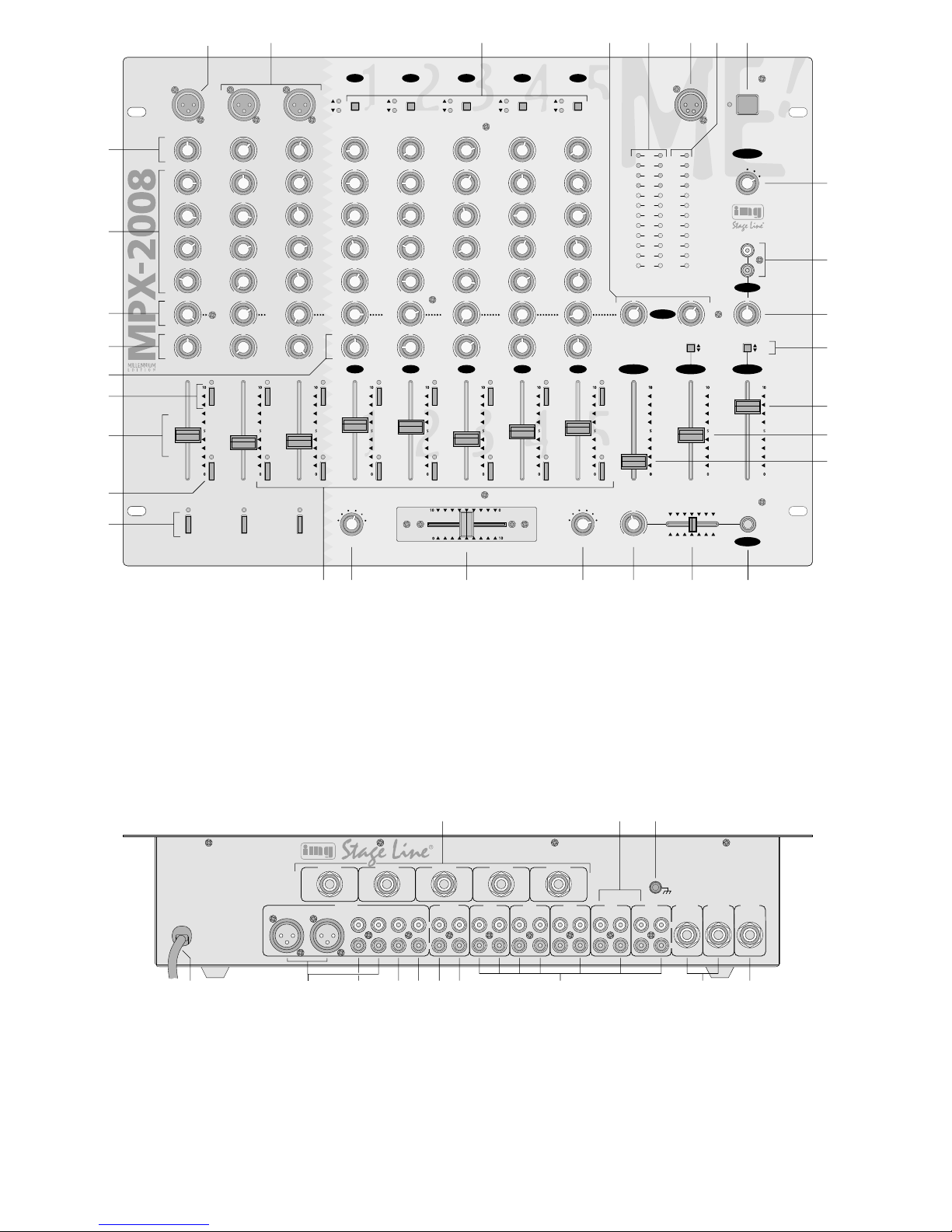
(9), the equalizer controls (10), panorama controls
(12), and balance controls (13) to mid-position first,
and the effect send controls (11) to minimum. Set
both ASSIGN switches (19 and 21) to “OFF” (cross-
fading function switched off).
1) To switch on the microphones connected to the
microphone channels DJ MIC, GUEST 1 and
GUEST 2, press the corresponding buttons ON
AIR (17).
2) Select the signal sources connected to the chan-
nels 1 to 5 with the selector buttons (3).
Button not pressed ( ):
the LINE input of the channel is selected.
Button pressed ( ):
The PHONO input (for channels 1 and 2) or CD
input (for channels 3 to 5) is selected.
3) With the two master faders the total level of all
connected audio sources is adjusted which is
available at the master outputs: master fader A
(31) for the two master outputs A (36), master
fader B (30) for the master output B (37).
Set the control of the master channel which is
used for the basic setting of the input channels to
approx. 2/3of the maximum position, e.g. to posi-
tion 7.
4) Set the stereo VU meter (5) with the rotary switch
DISPLAY (25) to the master channel which is
used for the basic setting of the input channels.
5) To control a channel, set the faders (15) of the
remaining channels to minimum and feed the
audio signals (test signals or music pieces) to the
respective input channel.
6) By means of the stereo VU meter, control the
level of the channel with the channel fader. The
optimum level is obtained if the 0dB range of the
VU meter shortly lights up with music peaks. If a
level beyond 0dB is displayed, the channel is
overloaded. After the level adjustment the fader
should be in approx. 2/3of the maximum position,
so that there is sufficient control range for fading
in and out.
If the fader is moved up very much or only moved
up very little, the level must be matched by ad-
justing the input amplification: turn up or turn
back the gain control (9) of the channel corre-
spondingly. For the channels 1 to 5 and the two
microphone channels GUEST 1 and 2 the PFL
VU meter (7) serves as control meter: slide the
MIX control (23) to position “PFL”, and press the
PFL button (18) of the channel. Then the PFL VU
meter shows the signal level of the channel
ahead of the channel fader.
7) Adjust the desired sound with the equalizer con-
trols of the channel:
HIGH control = high range (20kHz)
MID-H control = upper midrange (3kHz)
MID-L control = lower midrange (300Hz)
BASS control = bass range (20Hz)
All frequency ranges can be boosted or attenu-
ated up to max. 15dB.
If the controls are in mid-position, there is no
influence on the frequency response.
Note: Sound adustments influence the levels.
Therefore, after a sound adjustment, check the
channel level by means of the stereo VU meter
and correct it, if necessary.
8) Make the adjustments for the remaining con-
nected input channels in the same way as de-
scribed above.
5.1.2 Settings for the monitor system
The three microphone channels and the stereo
channels 1 to 5 can be monitored via a monitor
system connected to the MONITOR output (38). The
monitor way is a pre fader way, i.e. the channel sig-
nals are fed to the monitor way ahead of the channel
faders (15).
1) To switch one channel or several channels to the
monitor way, press the MON button (14) of the
respective channel.
2) Set the DISPLAY switch (25) to the position
“MONITOR”. In this position the stereo VU meter
(5) shows the level of the monitor output.
3) Adjust the desired level for the monitor system
with the monitor fader (29). In case of overload
(red LEDs of the VU meter light up), slide back
the fader correspondingly.
5.1.3 Settings when using an effect unit
The three microphone channels and the stereo
channels 1 to 5 can individually be fed to the effect
send way (for this also refer to chapter 4.3). The
effect send way is a pre fader way, therefore, the
position of the channel faders (15) does not influ-
ence the extent of the effect.
1) With the SEND controls (11) adjust for each
channel the level by which the channel signals
are mixed to the effect send way.
2) With the controls RETURN (4) adjust the level by
which the signals coming from the effect unit are
mixed to the stereo master.
5.2 Crossfading between two channels
1) With the two ASSIGN switches two channels of
the stereo input channels 1 to 5 are selected for
crossfading:
With the leftASSIGN switch (19) select the chan-
nel for fading in if the crossfader (20) is slid to the
left.
With the right ASSIGN switch (21) select the
channel for fading in if the crossfader is slid to the
right.
2) Set the faders (15) of the channels not used to
minimum. Obtain the optimum level control for
the two selected channels by means of their
faders (see chapter 5.1.1) and adjust the desired
balance with the balance controls BAL (13).
3) Crossfading between the two selected channels
is now possible with the crossfader.
For feeding the two channels to the outputs at
the same time, set the crossfader to mid-position.
4) With the master faders A and B (31 and 30) set
the desired total level for the master channels A
and B. Separately control each master channel
by means of the stereo VU meter (5). For this 7
GB
D
A
CH

nals umschalten. Bei Übersteuerungen (rote
LEDs des VU-Meters leuchten auf) den jeweili-
gen Masterfader entsprechend herunterregeln.
5.3 Mischen der Tonquellen
1) Zum Mischen der angeschlossenen Tonquellen
die Überblendfunktion ausschalten. Dazu die
ASSIGN-Schalter (19 und 21) auf „OFF“ stellen.
2) Den Masterfader A (31) oder B (30) so weit auf-
ziehen, daß das Mischungsverhältnis der Ton-
quellen optimal eingestellt werden kann.
3) Mit den Kanalfadern (15) das gewünschte Laut-
stärkeverhältnis der Tonquellen zueinander ein-
stellen. Wird ein Kanal nicht benutzt, sollte sein
Fader auf Minimum gestellt werden.
4) Mit den Panoramareglern PAN (12) die Signale
wie gewünscht auf der Stereo-Basis verteilen (für
die Mikrofonkanäle) bzw. mit den Balancereglern
BAL (13) die gewünschte Balance einstellen (für
die Stereo-Kanäle 1–5).
5) Zum Mischen der Signale des am Eingang AUX
IN (26) angeschlossenen Gerätes auf die Stereo-
Signalsumme den AUX IN-Pegelregler (27) wie
gewünscht aufdrehen.
6) Mit den Masterfadern jeden Masterkanal anhand
des Stereo-VU-Meters (5) separat ausregeln.
Dazu mit dem Drehschalter DISPLAY (25) das
Stereo-VU-Meter aufAnzeige des jeweiligen Ma-
sterkanals umschalten.
Die Masterkanäle sind optimal ausgesteuert,
wenn bei den lautesten Passagen der 0-dB-Be-
reich des VU-Meters kurz aufleuchtet. Bei Über-
steuerungen (rote LEDs leuchten) den jeweiligen
Masterfader und/oder die Pegelregler der Ein-
gangskanäle entsprechend herunterregeln.
5.4 Talkover-Funktion für das DJ-Mikrofon
Die Talkover-Funktion dient zur besseren Verständ-
lichkeit von Durchsagen über das DJ-Mikrofon bei
laufendem Musikprogramm. Zum Aktivieren der
Funktion die Taste AUTO TALK (16) drücken: Ist die
Taste gedrückt, werden bei Durchsagen über das
Mikrofon an der Buchse DJ MIC (1 oder 44) die Pegel
der Kanäle 1–5 automatisch um 12dB abgesenkt.
ZumAbschalten der Funktion die Taste wieder lösen.
5.5 Vorhören (PFL) über einen Kopfhörer
Über die Vorhörfunktion ist es möglich, die Mikrofon-
kanäle GUEST 1 und 2 und die Stereo-Eingangs-
kanäle 1–5 über einen an der Buchse PHONES (24)
angeschlossenen Kopfhörer abzuhören, auch wenn
der dazugehörige Kanalfader (15) auf Minimum steht.
Dadurch kann z.B. auf einer CD der gewünschte Titel
ausgewählt oder der richtige Zeitpunkt zum Einblen-
den einer Tonquelle abgepaßt werden.
Wahlweise ist es auch möglich, das laufende Mu-
sikprogramm vor den Masterfadern (30 und 31) ab-
zuhören.
1) Zum Abhören eines Eingangskanals vor dem Ka-
nalfader seine Taste PFL (18) drücken und den
Regler MIX (23) ganz nach links schieben (Posi-
tion „PFL“). Das PFL-VU-Meter (7) zeigt dann
den Pre Fader-Pegel des gewählten Kanals an.
Steht der Regler MIX ganz rechts (Position
„PROG.“) wird das laufende Musikprogramm vor
den beiden Masterfadern abgehört und vom PFL-
VU-Meter angezeigt.
2) Mit dem Pegelregler LEVEL (22) die gewünschte
Kopfhörerlautstärke einstellen.
ACHTUNG: Stellen Sie die Kopfhörerlautstärke
nie sehr hoch ein. Hohe Lautstärken können auf
Dauer das Gehör schädigen! Das menschliche
Ohr gewöhnt sich an große Lautstärken und emp-
findet sie nach einiger Zeit als nicht mehr so
hoch. Darum eine hohe Lautstärke nach der Ge-
wöhnung nicht weiter erhöhen.
5.6 Fernstarten von Platten- und CD-Spielern
Platten- und CD-Spieler mit Kontaktsteuerung (z.B.
CD-180DJ, CD-304DJ, DJP-202 aus dem Programm
von „img Stage Line“) an den Kanälen 1–5 können
über das Mischpult ferngestartet werden (Faderstart).
Ist das Gerät über eine Fernstart-Steuerleitung mit
dem Mischpult verbunden (siehe dazu Kap. 4.4),
wird beim Aufziehen des jeweiligen Faders (15) ein
Schalter geschlossen und startet dadurch den Plat-
ten- bzw. CD-Spieler. Wird der Fader auf Minimum
zurückgesetzt, öffnet der Schalter, und das ange-
schlossene Gerät stoppt bzw. schaltet auf Pause.
6 Technische Daten
Eingänge
Mic, mono: . . . . . . . . . . . . 1mV
Phono, stereo: . . . . . . . . . . 3mV
Line/CD, stereo: . . . . . . . . 150mV
Aux in, stereo: . . . . . . . . . . 150mV
Return, stereo: . . . . . . . . . 150mV
Ausgänge
Master A und B, stereo: . . . 1V
Monitor, stereo: . . . . . . . . . 1V
Record, stereo: . . . . . . . . . 300mV
Send, stereo: . . . . . . . . . . . 300mV
Kopfhörer, stereo: . . . . . . . ≥8Ω
Allgemeine Daten
Frequenzbereich: . . . . . . . 20–20000Hz
Klirrfaktor: . . . . . . . . . . . . . 0,03%
Störabstand: . . . . . . . . . . . > 45dB
Klangregler
8 x Tiefen: . . . . . . . . . . . ±15dB/20Hz
8 x Mitten-L: . . . . . . . . . ±15dB/300kHz
8 x Mitten-H: . . . . . . . . . ±15dB/3kHz
8 x Höhen: . . . . . . . . . . . ±15dB/20kHz
Talkover (automatisch): . . .
-
12dB
Anschluß für Pultleuchte: . 12V/5W; 4pol. XLR
Einsatztemperatur: . . . . . . 0–40°C
Stromversorgung: . . . . . . . 230V~/50Hz/30VA
Abmessungen (B x H x T): 482 x 355 x 115mm,
8 HE
Gewicht: . . . . . . . . . . . . . . 7,5kg
Laut Angaben des Herstellers.
Änderungen vorbehalten.
switch the stereo VU meter with the rotary switch
DISPLAY (25) to display the respective master
channel. In case of overload (red LEDs of the VU
meter light up), slide back the respective master
fader correspondingly.
5.3 Mixing of the audio sources
1) To mix the connected audio sources, switch off
the crossfading function. For this set theASSIGN
switches (19 and 21) to “OFF”.
2) Slide up the master fader A (31) or B (30) to a
position that allows to adjust the mixing relation
of the audio sources in an optimum way.
3) With the channel faders (15) adjust the desired
volume relation of the audio sources with each
other. If a channel is not used, its fader should be
set to minimum.
4) Distribute the signals to the stereo basis as de-
sired with the panorama controls PAN (12) (for
the microphone channels) or adjust the desired
balance with the balance controls BAL (13) (for
the stereo channels 1 to 5).
5) To mix the signals of the unit connected to the
AUX IN input (26) to the stereo master signal,
turn up the AUX IN level control (27) as desired.
6) With the master faders separately control each
master channel by means of the stereo VU meter
(5). For this switch the stereo VU meter with the
rotary switch DISPLAY (25) to display the respect-
ive master channel.
The levels of the master channels are con-
trolled in an optimum way if the 0dB range of the
VU meter shortly lights up with music peaks. In
case of overload (red LEDs light up), slide back
the respective master fader and/or the level con-
trols of the input channels correspondingly.
5.4 Talkover function for the DJ microphone
The talkover function serves for better intelligibility of
announcements via the DJ microphone during the
music programme. To activate the function, press the
AUTO TALK button (16): if the button is pressed, the
levels of channels 1 to 5 are automatically attenuated
by 12dB in case of announcements via the micro-
phone connected to the DJ MIC jack (1 or 44). To
switch off the function, release the button again.
5.5 Pre fader listening (PFL) via headphones
Via the pre fader function it is possible to monitor the
microphone channels GUEST 1 and 2 and the stereo
input channels 1 to 5 via headphones connected to
the PHONES jack (24) even if the corresponding
channel fader (15) is set to minimum. Thus, e.g. on a
CD the desired title can be selected or the right
moment for fading in an audio source can be timed.
Alternatively it is also possible to monitor the cur-
rent music programme ahead of the master faders
(30 and 31).
1) To monitor an input channel ahead of the channel
fader, press its PFL button (18) and slide the MIX
control (23) to the left stop (position “PFL”). Then
the PFLVU meter (7) shows the pre fader level of
the selected channel.
If the MIX control is set to the right stop (posi-
tion “PROG.”), the current music programme is
monitored ahead of the two master faders and
displayed by the PFL VU meter.
2) Adjust the desired headphone volume with the
LEVEL control (22).
CAUTION: Do not adjust the headphones to a
high volume. Permanent high volumes may
damage a person’s hearing! The human ear gets
accustomed to high volumes which do not seem to
be that high after some time. Therefore, do not fur-
ther increase a high volume after getting used to it.
5.6 Remote-controlling of turntables and CD
players
Turntables and CD players with contact control (e.g.
CD-180DJ, CD-304DJ, DJP-202 of the “img Stage
Line” range) connected to the channels 1 to 5 can
remotely be started via the mixer (fader start). If the
unit is connected via a remote start control line to the
mixer (for this see chapter 4.4), a switch is closed
when sliding up the respective fader (15) and thus
starts the turntable or CD player. If the fader is set
back to minimum, the switch opens and the con-
nected unit stops or switches to pause.
6 Specifications
Inputs
Mic, mono: . . . . . . . . . . . . 1mV
Phono, stereo: . . . . . . . . . . 3mV
Line/CD, stereo: . . . . . . . . 150mV
Aux in, stereo: . . . . . . . . . . 150mV
Return, stereo: . . . . . . . . . 150mV
Outputs
Master A and B, stereo: . . . 1V
Monitor, stereo: . . . . . . . . . 1V
Record, stereo: . . . . . . . . . 300mV
Send, stereo: . . . . . . . . . . . 300mV
Headphones, stereo: . . . . . ≥8Ω
General specifications
Frequency range: . . . . . . . 20–20000Hz
THD: . . . . . . . . . . . . . . . . . 0.03%
S/N ratio: . . . . . . . . . . . . . > 45dB
Equalizer
8 x bass: . . . . . . . . . . . . ±15dB/20Hz
8 x mid-L: . . . . . . . . . . . ±15dB/300kHz
8 x mid-H: . . . . . . . . . . . ±15dB/3kHz
8 x treble: . . . . . . . . . . . ±15dB/20kHz
Talkover (automatic): . . . . .
-
12dB
Connection for
console lamp: . . . . . . . . . . 12V/5W; 4-pole XLR
Ambient temperature: . . . . 0–40°C
Power supply: . . . . . . . . . . 230V~/50Hz/30VA
Dimensions (W x H x D): . . 482 x 355 x 115mm,
8 rack spaces
Weight: . . . . . . . . . . . . . . . 7.5kg
According to the manufacturer.
Subject to change.
8
GB
D
A
CH

Ouvrez le présent livret page 3 de manière à
visualiser les éléments et branchements.
Table des matières
1 Eléments et branchements . . . . . . . . . . . 9
1.1 Face avant . . . . . . . . . . . . . . . . . . . . . . . . . 9
1.2 Face arrière . . . . . . . . . . . . . . . . . . . . . . . . 10
2 Conseils d’utilisation . . . . . . . . . . . . . . . 10
3 Possibilités d’utilisation . . . . . . . . . . . . . 10
4 Branchements . . . . . . . . . . . . . . . . . . . . . 10
4.1 Entrées . . . . . . . . . . . . . . . . . . . . . . . . . . . 11
4.2 Sorties . . . . . . . . . . . . . . . . . . . . . . . . . . . . 11
4.3 Branchements pour un appareil à
effets spéciaux . . . . . . . . . . . . . . . . . . . . . . 11
4.4 Branchements pour commande à distance
de lecteurs CD ou platine disques . . . . . . . 11
4.5 Eclairage de la table et branchement
secteur . . . . . . . . . . . . . . . . . . . . . . . . . . . . 11
5 Fonctionnement . . . . . . . . . . . . . . . . . . . . 11
5.1 Réglages de base . . . . . . . . . . . . . . . . . . . 11
5.1.1 Réglage de base des canaux d’entrée . . 11
5.1.2 Réglages pour le système monitor . . . . . 12
5.1.3 Réglages en cas d’utilisation d’un
appareil à effets spéciaux . . . . . . . . . . . . 12
5.2 Fondu-enchaîné entre deux canaux . . . . . 12
5.3 Mixage des sources . . . . . . . . . . . . . . . . . 12
5.4 Fonction Talkover pour le micro DJ . . . . . . 13
5.5 Préécoute (PFL) via un casque . . . . . . . . . 13
5.6 Démarrage électrique de platine disque
et lecteur CD . . . . . . . . . . . . . . . . . . . . . . . 13
6 Caractéristiques techniques . . . . . . . . . 13
1 Eléments et branchements
1.1 Face avant
1Entrée XLR (sym) pour brancher un micro DJ
mono au canal DJ MIC; branchée en parallèle
avec la prise Jack 6,35 DJ MIC (44) située sur la
face arrière
2Entrées XLR (sym) pour brancher des micros
mono aux canaux GUEST 1 et GUEST 2; res-
pectivement en parallèle avec les prises Jack
6,35 GUEST 1 et GUEST 2 (43) de la face
arrière
3Sélecteurs des entrées des canaux 1–5:
touche non enfoncée ( ):
l’entrée LINE du canal est sélectionnée
touche enfoncée ( ):
l’entrée PHONO (canal 1 et 2) ou l’entrée CD
(canal 3–5) est sélectionnée
4Potentiomètres Return: réglage de niveau des
signaux venant de l’appareil à effets spéciaux
5VU-mètre stéréo: indique, selon la position du
commutateur (25) le niveau du canal master A,
du canal master B ou du canal monitor
6Prise XLR 4 pôles LAMP: branchement d’une
lampe pupitre (12V/5W max.)
7VU-mètre PFL: indique, selon la position du
réglage MIX (23) le niveau pré-fader du canal
d’entrée dont la touche PFL(18) est enfoncée ou
le programme musical en cours avant les faders
Master (30 et 31)
8Interrupteur Marche/Arrêt POWER
9Potentiomètres de réglage de Gain: réglage de
l’amplification d’entrée des canaux d’entrée
10 Egaliseur 4 voies pour les canaux d’entrée:
réglage HIGH: plage des aigus (20kHz)
réglage MID-H: plage supérieure des médiums
(3kHz)
réglage MID-L: plage inférieure des médiums
(300Hz)
réglage BASS: plage des graves (20Hz)
11 Potentiomètres SEND: réglage du niveau avec
lequel les signaux des canaux d’entrée sont
appliqués sur la voie d’effet pré-fader
12 Réglages de panoramique pour les canaux DJ
MIC et GUEST 1 et 2 pour répartir les signaux
mono sur la base stéréo
13 Potentiomètres de réglage de balance pour les
canaux stéréo 1–5
14 Touches MON: commutation des canaux d’en-
trée sur la voie monitor pré-fader
15 Potentiomètres de réglage de niveau (faders)
pour les canaux d’entrée
16 Touche AUTO TALK pour les annonces via le
micro DJ:
si la touche est enfoncée, les niveaux des ca-
naux 1–5 sont diminués de 12dB lors d’annon-
ces dans le micro DJ.
17 Touches ON AIR pour les micros DJ MIC et
GUEST 1 et 2: Marche /Arrêt de chaque micro
18 Touches PFL: pour faire une préécoute des ca-
naux d‘entrée mono GUEST 1 et 2 et des canaux
d’entrée stéréo 1–5 avant le fader (15) corres-
pondant, via un casque relié à la prise PHONES
(24)
19 Commutateur ASSIGN d’attribution pour le
potentiomètre de fondu-enchaîné (20); déter-
mine lequel des canaux 1–5 est utilisé pour le
fondu-enchaîné lorsque le potentiomètre de
fondu-enchaîné est à gauche
20 Potentiomètre de fondu-enchaîné entre les ca-
naux 1–5; les canaux sont sélectionnés avec
les deux commutateurs ASSIGN (19 et 21)
21 Commutateur ASSIGN d’attribution pour le
potentiomètre de fondu-enchaîné (20); déter-
mine lequel des canaux 1–5 est utilisé pour le
fondu-enchaîné lorsque le potentiomètre de
fondu-enchaîné est à droite
22 Réglage de niveau pour le casque relié à la prise
PHONES (24)
23 Potentiomètre MIX pour la sortie casque (24) et
le VU-mètre mono (7):
position “PFL” (à gauche):
le niveau pré fader du canal d’entrée dont la
touche PFL (18) est enfoncée est écouté dans
le casque et affiché sur le VU-mètre
Vi consigliamo di aprire completamente la
pagina 3. Così vedrete sempre gli elementi di
comando e i collegamenti descritti.
Indice
1 Gli elementi di comando e i
collegamenti . . . . . . . . . . . . . . . . . . . . . . . 9
1.1 Pannello frontale . . . . . . . . . . . . . . . . . . . . . 9
1.2 Pannello posteriore . . . . . . . . . . . . . . . . . . 10
2 Avvertenze di sicurezza . . . . . . . . . . . . . 10
3 Possibilità d’impiego . . . . . . . . . . . . . . . 10
4 Collegamento del mixer . . . . . . . . . . . . . 11
4.1 Ingressi . . . . . . . . . . . . . . . . . . . . . . . . . . . 11
4.2 Uscite . . . . . . . . . . . . . . . . . . . . . . . . . . . . . 11
4.3 Collegamenti per un’unità per effetti . . . . . 11
4.4 Collegamenti per il telecomando
di lettori CD e giradischi . . . . . . . . . . . . . . . 11
4.5 Illuminazione del mixer e
collegamento rete . . . . . . . . . . . . . . . . . . . 11
5 Funzionamento . . . . . . . . . . . . . . . . . . . . 11
5.1 Regolazione base . . . . . . . . . . . . . . . . . . . 11
5.1.1 Regolazione base dei canali d’ingresso . 11
5.1.2 Impostazioni per l’impianto di
monitoraggio . . . . . . . . . . . . . . . . . . . . . . 12
5.1.3 Impostazioni con l’impiego di un’unità
per effetti . . . . . . . . . . . . . . . . . . . . . . . . . 12
5.2 Dissolvenze fra due canali . . . . . . . . . . . . 12
5.3 Miscelare le sorgenti . . . . . . . . . . . . . . . . . 12
5.4 Funzione talkover per il microfono DJ . . . . 13
5.6 Preascolto (PFL) con una cuffia . . . . . . . . 13
5.7 Avvio telecomandato di giradischi e
lettori CD . . . . . . . . . . . . . . . . . . . . . . . . . . 13
6 Dati tecnici . . . . . . . . . . . . . . . . . . . . . . . . 13
1 Gli elementi di comando e i collega-
menti
1.1 Pannello frontale
1Ingresso XLR (simm.) per il collegamento di un
microfono DJ mono al canale DJ MIC; in parallelo
con la presa jack 6,3mm DJ MIC (44) sul retro
2Ingressi XLR (simm.) per il collegamento di
microfoni mono ai canali GUEST 1 e GUEST 2;
ognuno in parallelo con le prese jack 6,3mm
GUEST 1 e GUEST 2 (43) sul retro
3Commutatori per gli ingressi dei canali 1–5
tasto non premuto ( ):
è selezionato l’ingresso LINE del canale
tasto premuto ( ):
sono selezionati rispettivamente gli ingressi
PHONO (canali 1 e 2) o CD (canali 3–5)
4Regolatori Return per impostare il livello dei se-
gnali che ritornano dall’unità per effetti
5VU-metro stereo, indica – a seconda della posi-
zione del commutatore (25) – il livello del canale
masterA, del canale master B o del canale moni-
tor
6Presa XLR a 4 poli LAMP per il collegamento di
una lampada (12V/5W max.)
7VU-metro PFL, indica – a seconda della posi-
zione del regolatore MIX (23) – il livello del
canale d’ingresso, il cui tasto PFL (18) è pre-
muto, prima del fader oppure il programma musi-
cale attuale prima dei master fader (30 e 31)
8Interruttore on/off POWER
9Regolatori GAIN per regolare il guadagno
dell’amplificazione all’ingresso dei canali
10 Regolazione toni con 4 frequenze diverse per i
canali d’ingresso:
HIGH = alti (20kHz)
MID-H = medi superiori (3kHz)
MID-L = medi inferiori (300Hz)
BASS = bassi (20Hz)
11 Regolatori SEND per impostare il livello con cui i
segnali dei canali d’ingresso sono portati sulla
via degli effetti prima del fader (pre-fader)
12 Regolatori panoramico per i canali micro DJ MIC
e GUEST 1 e 2, per distribuire i segnali mono
sulla base stereo
13 Regolatori bilanciamento per i canali stereo 1–5
14 Tasti MON per portare i canali d’ingresso sulla
via pre-fader del monitor
15 Regolatori del livello dei canali d’ingresso (fader)
16 TastoAUTO TALK per avvisi con il microfono DJ:
se il tasto è premuto, i livelli dei canali 1–5
saranno abbassati di 12dB durante gli avvisi
17 Tasti ONAIR per i canali micro DJ MIC e GUEST
1 e 2 per attivare/disattivare il relativo microfono
18 Tasti PFL per il preascolto dei canali d’ingresso
mono GUEST 1 e 2 e dei canali d’ingresso ste-
reo 1–5 prima del relativo fader (15) tramite una
cuffia collegata con la presa PHONES (24)
19 Commutatore di assegnazione ASSIGN per il
crossfader (20); determina quale dei canali 1–5
sarà inserito quando il crossfader si trova a sini-
stra
20 Crossfader per creare dissolvenze fra i canali
1–5; con i due commutatori di assegnazione
ASSIGN (19 e 21) si scelgono i due canali
21 Commutatore di assegnazione ASSIGN per il
crossfader (20); determina quale dei canali 1–5
sarà inserito quando il crossfader si trova a
destra
22 Regolatore livello per la cuffia alla presa
PHONES (24)
23 Regolatore MIX per l’uscita cuffia (24) e per il
VU-metro mono (7)
posizione “PFL” (regolatore tutto a sinistra)
il livello pre-fader del canale d’ingresso il cui
tasto PFL (18) è premuto viene ascoltato attra-
verso la cuffia e visualizzato dal VU-metro
posizione “PROG.” (regolatore tutto a destra)
il programma attuale di musica viene ascoltato
prima dei master fader (30 e 31) attraverso la
cuffia e visualizzato dal VU-metro
24 Presa jack 6,3mm PHONES per il collegamento
di una cuffia stereo (impedenza ≥2 x 8Ω)9
I
F
B
CH

position “PROG.” (à droite):
le programme musicale en cours est écouté
dans le casque avant les faders master (30 et
31) et affiché sur le VU-mètre
24 Prise Jack 6,35 PHONES: branchement d’un
casque stéréo (impédance ≥2 x 8Ω)
25 Commutateur rotatif pour le VU-mètre stéréo (5):
position “MASTER A”:
le niveau du canal master A est affiché
position “MASTER B”:
le niveau du canal master B est affiché
position “MONITOR”:
le niveau du canal monitor est affiché
26 Entrée stéréo AUX IN: branchement d’un
appareil supplémentaire à sortie niveau Ligne
(par exemple, seconde table de mixage, platine-
cassette)
27 Réglage de niveau pour l’appareil relié à l’entrée
AUX IN (26)
28 Sélecteurs pour le canal master B et le canal
monitor
touche non enfoncée ( ):
le canal est commuté sur stéréo
touche enfoncée ( ):
le canal est commuté sur mono
29 Réglage de niveau (fader) du canal monitor
30 Réglage de niveau (fader) du canal master B
31 Réglage de niveau (fader) du canal master A
1.2 Face arrière
32 Prises Jack 6,35 START pour le démarrage élec-
trique de platine disques ou lecteurs CD à com-
mande par contact
33 Entrées stéréo PHONO (RCA) pour les canaux 1
et 2: branchement de platine disques à système
magnétique
34 Branchement GND pour une mise à la masse
commune, par exemple pour les platine disques
reliées
35 Cordon secteur à relier à une prise secteur
230V~/50Hz
36 Sorties stéréo du canal master A – au choix XLR
(sym) ou RCA – pour brancher un amplificateur
37 Sortie stéréo du canal master B (RCA) pour
brancher un amplificateur; la sortie peut être
commutée avec la touche (28) correspondante
sur mono
38 Sortie monitor stéréo (RCA) pour brancher un
système monitor; la sortie peut être commutée
avec la touche (28) correspondante sur mono
39 Sortie stéréo REC (RCA) pour brancher un enre-
gistreur; le niveau d’enregistrement est indépen-
dant de la position des faders master (30 et 31)
40 Entrée stéréo RETURN (RCA): connexion à la
sortie d’un appareil à effets spéciaux
41 Sortie stéréo SEND (RCA): connexion à l’entrée
d’un appareil à effets spéciaux
42 Entrées stéréo LINE et CD (RCA) pour les ca-
naux 1–5: branchement d’appareils à sorties
niveau Ligne (par exemple, lecteur CD, enregis-
treur de mini-disques, platine-cassette)
43 Prises Jack 6,35 (sym) pour brancher des micros
mono aux canaux GUEST 1 et GUEST 2; bran-
chées respectivement en parallèle aux prises
XLR GUEST 1 et GUEST 2 (2) de la face avant
44 Prise Jack 6,35 (sym) pour brancher un micro
mono au canal DJ MIC; branchée en parallèle
avec la prise XLR DJ MIC (1) de la face avant
2 Conseils d’utilisation
La table de mixage MPX-2008 répond à la norme
européenne 89/336/CEE relative à la compatibilité
électromagnétique et à la norme 73/23/CEE portant
sur les appareils à basse tension.
Cet appareil est alimenté par une tension très
dangereuse de 230V~. Ne touchez jamais
l’intérieur de l’appareil car en cas de mauvaise
manipulation, vous pourriez subir une décharge
électrique mortelle. En outre, l’ouverture de l’ap-
pareil rend tout droit à la garantie caduque.
Respectez scrupuleusement les points suivants:
●Cet appareil n’est conçu que pour une utilisation
en intérieur; protégez-le de l’humidité et de la cha-
leur (température ambiante 0–40°C).
●Ne le faites pas fonctionner et débranchez-le lors-
que:
1. des dommages sur l’appareil ou le cordon sec-
teur apparaissent.
2. après une chute ou un cas similaire, vous avez
un doute sur l’état de l’appareil.
3. des dysfonctionnements apparaissent.
Dans tous les cas, les dommages doivent être
réparés par un technicien spécialisé.
●Tout cordon secteur endommagé ne doit être rem-
placé que par le fabricant ou par un réparateur
agréé.
●Ne débranchez jamais la table de mixage en tirant
sur le cordon secteur.
●Nous déclinons toute responsabilité en cas de
dommage si l’appareil est utilisé dans un but autre
que celui pour lequel il a été conçu, s’il n’est pas
correctement branché, utilisé ou réparé par une
personne habilitée.
●Pour nettoyer l’appareil, n’utilisez qu’un chiffon
sec et doux, en aucun cas de produits chimiques
ou d’eau.
●Lorsque l’appareil est définitivement retiré du cir-
cuit de distribution, vous devez le déposer dans
une usine de recyclage adaptée.
3. Possibilités d’utilisation
La table de mixage MPX-2008 est équipée de 5 ca-
naux d‘entrée stéréo, de 2 canaux micro GUEST 1
et 2 et d’un canal micro DJ; elle est parfaitement
adaptée pour des utilisations de DJ privées ou pro-
fessionnelles.
La table peut être posée directement sur une
table ou intégrée dans un pupitre ou placée dans un
rack au standard 482mm (19"). Pour le montage
dans un rack, 8 unités (1 unité = 44,45mm) sont
nécessaires.
4 Branchements
Avant d’effectuer tout branchement ou de modifier
les branchements existants, veillez à débrancher la
table du secteur.
25 Selettore per il VU-metro stereo (5)
posizione “MASTER A”
si visualizza il livello del canale master A
posizione “MASTER B”
si visualizza il livello del canale master B
posizione “MONITOR”
si visualizza il livello del canale monitor
26 Ingresso stereoAUX IN per il collegamento di un
apparecchio supplementare con livello d’uscita
Line (p.es. di un secondo mixer o di un tape-
deck)
27 Regolatore del livello per l’apparecchio collegato
con l’ingresso AUX IN (26)
28 Commutatori per il canale master B e il canale
monitor
tasto non premuto ( ):
il canale è stereo
tasto premuto ( ):
il canale è mono
29 Regolatore livello (fader) per il canale monitor
30 Regolatore livello (fader) per il canale master B
31 Regolatore livello (fader) per il canale master A
1.2 Pannello posteriore
32 Prese jack 6,3mm START per il collegamento di
un cavo di comando per l’avvio telecomandato di
giradischi e lettori CD con comando a contatto
33 Ingressi stereo PHONO (cinch) per i canali 1 e 2
per il collegamento di giradischi con sistema
magnetico
34 Contatto comune di massa GND, p.es. per i
giradischi collegati
35 Cavo rete per il collegamento con l’alimenta-
zione (230V~/50Hz)
36 Uscite stereo del canale masterA – a scelta XLR
(simm.) oppure cinch – per il collegamento di
uno stadio finale
37 Uscite stereo del canale master B (cinch) per il
collegamento di uno stadio finale; con il tasto
(28), il canale può essere messo su mono
38 Uscita stereo monitor (cinch) per il collegamento
di un impianto monitor; con il tasto (28), il canale
può essere messo su mono
39 Uscita stereo REC (cinch) per il collegamento di
un registratore; li livello di registrazione non
dipende dalla posizione dei master fader (30 e
31)
40 Ingresso stereo RETURN (cinch) per il collega-
mento all’uscita di un’unità per effetti
41 Uscita stereo SEND (cinch) per il collegamento
all’ingresso di un’unità per effetti
42 Ingressi stereo LINE o CD (cinch) per i canali
1–5 per il collegamento di apparecchi con livello
d’uscita Line (p.es. lettore CD, registratore a
cassette, registratore per mini disk)
43 Prese jack 6,3mm (simm.) per il collegamento di
microfoni mono ai canali GUEST 1 e GUEST 2;
in parallelo con le prese XLR GUEST 1 e
GUEST 2 (2) sul pannello frontale
44 Presa jack 6,3mm (simm.) per il collegamento di
un microfono mono ai canali DJ MIC; in parallelo
con la presa XLR DJ MIC (1) sul pannello fron-
tale
2 Avvertenze di sicurezza
Questo apparecchio corrisponde alle direttive CE
89/336/CEE sulla compatibilità elettromagnetica e
73/23/CEE per apparecchi a bassa tensione.
L’apparecchio funziona con tensione di rete di
230V~. Non intervenire mai al suo interno; la
manipolazione scorretta può provocare delle sca-
riche pericolose. Se l’apparecchio viene aperto,
cessa ogni diritto di garanzia.
Si devono osservare assolutamente i seguenti
punti:
●L’apparecchio è previsto solo per l’uso all’interno
di locali. Proteggerlo dall’umidità e dal calore
(temperatura d’impiego ammessa 0–40°C.).
●Non mettere in funzione l’apparecchio e staccare
subito la spina rete se:
1. l’apparecchio o il cavo rete presentano dei
danni visibili;
2. dopo una caduta o dopo eventi simili sussiste il
sospetto di un difetto;
3. l’apparecchio non funziona correttamente.
Per la riparazione rivolgersi sempre ad una offi-
cina competente.
●Il cavo rete, se danneggiato, deve essere sosti-
tuito solo dal costruttore o da un laboratorio auto-
rizzato.
●Staccare il cavo rete afferrando la spina, senza ti-
rare il cavo.
●Nel caso di uso improprio, di collegamento sba-
gliato, di impiego scorretto o di riparazione non a
regola d’arte dell’apparecchio non si assume nes-
suna responsabilità per eventuali danni.
●Per la pulizia usare solo un panno asciutto e mor-
bido; non impiegare in nessun caso prodotti chi-
mici o acqua.
●Se si desidera eliminare l’apparecchio definitiva-
mente, consegnarlo per lo smaltimento ad un’isti-
tuzione locale per il riciclaggio.
3 Possibilità d’impiego
Il mixer MPX-2008 con cinque canali stereo d’in-
gresso, due canali microfono GUEST 1 e 2 e con un
canale per il microfono DJ è adatto per impieghi DJ
professionali e privati.
L’apparecchio può essere collocato liberamente
o montato in un piano di comando. È possibile
anche la sistemazione in un rack (482mm/19"). Per
il montaggio in un rack sono richieste 8 unità di
altezza (= 8 x 44,45mm).
10
I
F
B
CH

4.1 Entrées
1) Reliez les sources aux prises d’entrée corres-
pondantes [entrées mono pour les 3 canaux
micro, entrées stéréo pour les canaux 1–5 (prise
blanche L = canal gauche, prise rouge R: canal
droit)].
-
un micro DJ à la prise DJ MIC (1 ou 44)
-
deux autres micros aux prises GUEST 1 et
GUEST 2 (2 ou 43)
-
appareils à sortie niveau Ligne (par exemple,
lecteur CD, enregistreur de mini-disques, pla-
tine-cassette) aux prises CD ou LINE (42)
-
platine disques à système magnétique aux pri-
ses PHONO (33); la borne GND (34) peut être
utilisée comme masse commune: reliez le
branchement masse de la platine disque à la
borne à vis
2) Il est possible de relier à l’entrée stéréo AUX IN
(26) un autre appareil à sortie niveau Ligne; de
même, l’entrée stéréo RETURN (40) – dans la
mesure où elle n’est pas prévue pour un appareil
à effets spéciaux – peut être utilisée comme en-
trée supplémentaire pour une source Ligne. Les
signaux des appareils reliés à ces prises sont
mixés sur le master stéréo avec le réglage AUX
IN (27)/les réglages RETURN (4).
4.2 Sorties
1) Reliez les amplificateurs aux prises de sortie cor-
respondantes:
-
la somme du canal masterA est disponible aux
deux sorties stéréo (36); il est possible d’utili-
ser la sortie XLR symétrique (LEFT = canal
gauche, RIGHT = canal droit) ou la sortie
asymétrique RCA.
-
la somme du canal master B est disponible à la
sortie stéréo B (37). [En enfonçant la touche
(28) du canal, la sortie est commutable sur
mono.]
2) Si un système monitor est prévu, reliez l’amplifi-
cateur du système monitor à la sortie stéréo
MONITOR (38). [En enfonçant la touche (28) du
canal, la sortie est commutable sur mono.]
3) Si vous effectuez des enregistrements, reliez
l’enregistreur à la sortie stéréo REC (39); le
niveau d’enregistrement est indépendant de la
position des faders master (30 et 31).
4) Via un casque stéréo, on peut faire une pré-
écoute du niveau pré fader des canaux GUEST 1
et 2 et des canaux stéréo 1–5 ainsi que du pro-
gramme musical en cours avant les faders
master (voir chapitre 5.5). Reliez le casque (im-
pédance ≥2 x 8Ω) à la prise PHONES (24).
4.3 Branchements pour un appareil à effets
spéciaux
Via les branchements stéréo SEND (41) et
RETURN (40), il est possible d’extraire des signaux
des canaux 1–5 et des trois canaux micro de la
table, de les insérer dans un appareil à effets spé-
ciaux (par exemple égaliseur, appareil à effets
réverbération) et de les diriger à nouveau vers la
table. La voie Effet Send est pré fader, c’est-à-dire
les signaux sont appliqués sur la voie d’effet avant
les faders des canaux (15).
1) Reliez l’entrée de l’appareil à effets spéciaux aux
prises SEND.
2) Reliez la sortie de ce même appareil aux prises
RETURN.
4.4 Branchements pour commande à dis-
tance de lecteurs CD ou platine disques
Les lecteurs CD ou platine disques à commande par
contact, reliés aux canaux 1–5, peuvent être com-
mandés à distance via la table de mixage. Connec-
tez l’entrée commande de l’appareil à la prise
START (32) correspondante de la table de mixage.
Fig. 3: Interrupteur de démarrage électrique pour un canal
Attention: Les interrupteurs de démarrage électri-
que ne sont pas adaptés pour allumer une tension
secteur! Risque de décharge électrique.
4.5 Eclairage de la table et branchement
secteur
Il est possible de brancher une lampe col de cygne
(12V/5W max.) à la prise LAMP (6), par exemple la
lampe GNL-405 de la gamme “img Stage Line”. La
lampe est allumée/éteinte depuis la table.
Reliez maintenant le cordon secteur (35) à une
prise secteur 230V~/50Hz.
5 Fonctionnement
Avant d’allumer la table, mettez les potentiomètres
master (30 et 31) et le potentiomètre monitor (29)
sur le minimum de manière à éviter tout bruit fort lors
de l’allumage. Allumez la table avec l’interrupteur
POWER (8) la LED rouge, témoin de fonctionne-
ment a côté de l’interrupteur, brille. Allumez ensuite
les divers appareils reliés.
5.1 Réglages de base
5.1.1 Réglage de base des canaux d’entrée
Pour un réglage optimal du niveau des sources
reliées aux canaux d’entrée, mettez les réglages de
gain (9), égaliseur (10), panoramique (12) et de
balance (13) sur la position médiane puis les régla-
ges Effet Send (11) sur le minimum. Mettez les deux
commutateurs ASSIGN (19 + 21) sur “OFF” (fonc-
tion fondu-enchaîné déconnectée).
1) Pour allumer les micros reliés aux canaux DJ
MIC, GUEST 1 et GUEST 2, enfoncez les tou-
ches ON AIR correspondantes (17).
2) Avec les touches (3), sélectionnez les sources
reliées aux canaux 1–5.
touche non enfoncée ( ):
l’entrée LINE du canal est sélectionnée
START
Start
Stop
/
Pause
4 Collegamento del mixer
Prima di eseguire o modificare i collegamenti oc-
corre spegnere il mixer.
4.1 Ingressi
1) Collegare le sorgenti con i relativi ingressi dei
canali d’ingresso [ingressi mono per i tre canali
microfono, ingressi stereo per i canali 1–5
(presa bianca L = canale sinistro, presa rossa R
= canale destro):
-
un microfono DJ con la presa DJ MIC (1 o 44)
-
due ulteriori microfoni con le prese GUEST 1 e
GUEST 2 (2 o 43)
-
apparecchi con livello d’uscita Line (p.es. let-
tore CD, registratore mini-disk, registratore a
cassette) alle prese CD o LINE (42)
-
giradischi con sistema magnetico alle prese
PHONO (33). La vite GND (34) può servire
come massa comune: collegare il cavo di
massa del giradischi con tale vite.
2) All’ingresso stereo AUX IN (26) si può collegare
un ulteriore apparecchio con uscita Line. Anche
l’ingresso stereo RETURN (40) – se non è previ-
sto per il collegamento di un’unità per effetti (vedi
cap. 4.3) – può essere sfruttato come ingresso
supplementare per una sorgente Line. I segnali
degli apparecchi collegati con dette prese ven-
gono miscelati sulla somma stereo tramite i rego-
latori AUX IN (27) o RETURN (4).
4.2 Uscite
1) Collegare gli amplificatori con le relative prese
d’uscita:
-
La somma dei segnali del canale master A è
disponibile alle due uscite stereo (36). Si può
utilizzare a scelta l’uscita simmetrica XLR
(LEFT = canale di sinistra, RIGHT = canale di
destra) oppure l’uscita asimmetrica cinch.
-
La somma dei segnali del canale master B è
disponibile all’uscita stereo B (37). [Premendo
il tasto commutatore (28) del canale, l’uscita
può essere messa su mono.]
2) Se è presente un impianto di monitoraggio, colle-
gare l’amplificatore dell’impianto con l’uscita ste-
reo MONITOR (38). [Premendo il tasto commuta-
tore (28) del canale, l’uscita può essere messa
su mono.]
3) Per eventuali registrazioni audio, collegare un
registratore alle prese d’uscita REC (39). Il livello
di registrazione è indipendente dalla posizione
dei due master fader (30 e 31).
4) Con una cuffia stereo è possibile ascoltare sia il
livello prima del fader dei canali micro GUEST 1
e 2 e dei canali stereo 1–5, sia il programma
attuale di musica prima dei master fader (vedi
cap. 5.5). Collegare la cuffia (impedenza = 2
x8Ω) con la presa PHONES (24).
4.3 Collegamenti per un’unità per effetti
Con le prese stereo SEND (41) e RETURN (40) è
possibile fare uscire dal mixer i segnali dei canali
d’ingresso 1–5 nonché dei tre canali micro, farli
passare attraverso un’unità per effetti (p.es. un
equalizzatore o un riverbero) e farli ritornare nel
mixer. La via effect-send è una via “pre-fader”; ciò
significa che i segnali dei canali entrano nella via
degli effetti a monte dei fader dei canali (15).
1) Collegare l’ingresso dell’unità per effetti con le
prese SEND.
2) Collegare l’uscita dell’unità per effetti con le
prese RETURN.
4.4 Collegamenti per il telecomando di let-
tori CD e giradischi
Tramite il mixer, ai canali 1 –5, è possibile l’avvio tele-
comandato di lettori CD e giradischi con comando a
contatti. Per fare ciò collegare il relativo ingresso di
comando dell’apparecchio collegato con la relativa
presa jack 6,3mm START (32) del mixer.
Fig. 3: Avvio telecomandato per un canale
Attenzione: L’interruttore per telecomando non è
adatto per comandare la tensione di rete! Pericolo di
scossa elettrica!
4.5 Illuminazione del mixer e collegamento
rete
Per un’illuminazione ottimale del mixer si può colle-
gare una lampada a collo di cigno (12V/max. 5W),
p.es. GNL-405 della “img Stage Line”, alla presa
XLR LAMP (6). La lampada si accende e si spegne
insieme al mixer.
Alla fine inserire la spina del cavo rete (35) in una
presa di rete (230V~/50Hz).
5 Funzionamento
Prima di accendere il mixer e per evitare i rumori di
commutazione, posizionare i due master fader (30 e
31) nonché il regolatore monitor (29) sul minimo.
Quindi accendere il mixer con l’interruttore POWER
(8). Se il mixer è acceso, rimane acceso il LED
rosso vicino all’interruttore. A questo punto accen-
dere gli apparecchi collegati.
5.1 Regolazioni base
5.1.1 Regolazione base dei canali d’ingresso
Per una regolazione ottimale dei livelli degli appa-
recchi collegati, portare tutti i regolatori gain (9), i
regolatori dei toni (10), i regolatori del bilanciamento
(13) e panoramico (12) in posizione centrale e chiu-
dere completamente i regolatori di effetti SEND (11).
Mettere i due commutatori di assegnazioneASSIGN
(19 e 21) su “OFF” (funzione di dissolvenza disatti-
vata).
1) Per attivare i microfoni collegati ai canali DJ MIC,
GUEST 1 e GUEST 2 premere il relativo tasto
ON AIR (17).
2) Con i tasti di commutazione (3) selezionare le
sorgenti collegate con i canali 1–5.
Tasto non premuto ( ):
è selezionato l’ingresso LINE del canale.
START
Start
Stop
/
Pause
11
I
F
B
CH

touche enfoncée ( ):
l’entrée PHONO (pour canal 1 et 2) ou CD
(pour canal 3–5) est sélectionnée
3) Les deux faders master permettent de régler le
niveau total de toutes les sources reliées, dispo-
nible aux sorties master: fader masterA(31) pour
les deux sorties master A (36), fader master B
(30) pour la sortie master B (37).
Mettez le potentiomètre du canal master uti-
lisé pour le réglage de base des canaux d’entrée
à 2/3environ du maximum, par exemple sur la
position 7.
4) Commutez le VU-mètre stéréo avec le commuta-
teur DISPLAY (25) sur le canal master utilisé
pour le réglage de base des canaux d’entrée.
5) Pour contrôler un canal, mettez les faders (15)
des canaux restants sur le minimum et appliquez
les signaux audio (signaux de test ou morceaux
de musique) sur le canal d’entrée respectif.
6) Selon les indications du VU-mètre stéréo, réglez
le niveau du canal avec son fader. Le réglage est
optimal lorsque, pour des passages les plus éle-
vés, la plage 0dB du VU-mètre brille brièvement.
Il y a surcharge lorsque la plage au-dessus de
0dB brille. Une fois le réglage effectué, le poten-
tiomètre doit être à 2/3environ du maximum de
manière à avoir assez de place pour effectuer le
fondu-enchaîné.
Si le fader n’est pas assez poussé, ou s’il est
trop poussé, le niveau doit être adapté en régu-
lant l’amplification d’entrée: selon le cas, tournez
le réglage de gain (9) du canal à droite ou à gau-
che. Pour les canaux 1 à 5 et les deux canaux
micro GUEST 1 et 2, le VU-mètre PFL(7) sert de
contrôle: poussez le réglage MIX (23) sur la posi-
tion “PFL” et enfoncez la touche PFL (18) du
canal. Le VU-mètre indique alors le niveau du
canal avant le fader.
7) Réglez l’image tonale du signal avec l’égaliseur
du canal:
réglage HIGH: plage des aigus (20kHz)
réglage MID-H: plage supérieure des médiums
(3kHz)
réglage MID-L: plage inférieure des médiums
(300Hz)
réglage BASS: plage des graves (20Hz)
Toutes les plages de fréquence peuvent être
augmentées ou diminuées de 15dB maximum.
Si les potentiomètres sont sur la position
médiane, il n’y a pas de modification.
Remarque: les réglages agissent sur le niveau.
Après chaque réglage, contrôlez le niveau du
canal en fonction des indications du VU-mètre
stéréo et, si nécessaire, corrigez-le.
8) Effectuez les réglages de la même façon pour les
autres canaux comme décrit ci-dessus.
5.1.2 Réglages pour le système monitor
Il est possible de faire une préécoute des trois ca-
naux micro et des canaux stéréo 1–5 via un
système monitor relié à la sortie MONITOR (38). La
voie monitor est une voie pré fader, c’est-à-dire les
signaux sont appliqués sur la voie monitor avant les
faders (15).
1) Pour commuter un canal/plusieurs canaux sur la
voie monitor, enfoncez la touche MON (14) du
canal.
2) Mettez le commutateur DISPLAY (25) sur la posi-
tion “MONITOR”; le VU-mètre stéréo (5) indique
alors le niveau à la sortie monitor.
3) Avec le fader monitor (29), réglez le niveau sou-
haité pour le système monitor. En cas de sur-
charges (LEDs rouges du VU-mètre allumées),
diminuez le fader.
5.1.3 Réglages en cas d’utilisation d’un appa-
reil à effets spéciaux
Il est possible d’appliquer séparément les trois ca-
naux micro et les canaux stéréo 1–5 sur la voie
Effet Send (voir chapitre 4.3). La voie Effet Send est
une voie pré fader, la position des faders (15) n’a
pas d’influence sur l‘intensité de l’effet.
1) Avec les potentiomètres SEND (11), réglez pour
chaque canal le niveau avec lequel les signaux
son mixés sur la voie Effet Send.
2) Avec les potentiomètres RETURN (31) – LEFT =
canal gauche, RIGHT = canal droit – réglez le
niveau avec lequel les signaux venant de l’ap-
pareil à effets sont mixés sur la somme stéréo.
5.2 Fondu-enchaîné entre deux canaux
1) Avec les deux commutateurs ASSIGN, sélec-
tionnez les deux canaux parmi les canaux 1–5
entre lesquels le fondu-enchaîné est effectué:
Avec le commutateur ASSIGN gauche (19),
sélectionnez le canal utilisé pour le fondu-
enchaîné lorsque le potentiomètre de fondu-
enchaîné (20) est à gauche.
Avec le commutateur ASSIGN droit (21), sélec-
tionnez le canal utilisé pour le fondu-enchaîné
lorsque le potentiomètre de fondu-enchaîné est à
droite.
2) Mettez les faders (15) des canaux non utilisés
sur le minimum. Pour les deux canaux sélec-
tionnés, réglez le niveau optimal avec leurs
faders (voir chapitre 5.1.1) et réglez la balance
avec les potentiomètres BAL (13).
3) Le potentiomètre de fondu-enchaîné permet de
faire un fondu-enchaîné entre les deux canaux
sélectionnés.
Mettez-le sur la position médiane si les deux
canaux doivent être appliqués simultanément sur
les sorties.
4) Réglez le niveau total souhaité avec les faders
masterA et B (31 et 30) pour les canaux master A
et B. Réglez chaque canal master séparément
selon les indications du VU-mètre stéréo (5). Pour
faire cela, commutez avec le commutateur DIS-
PLAY (25) le VU-mètre stéréo sur l’affichage du
canal master correspondant. En cas de surcharge
(LEDs rouges du VU-mètre allumées), diminuez
les faders masters de manière adéquate.
5.3 Mixage des sources
1) Pour mixer les sources reliées, déconnectez la
fonction fondu-enchaîné: mettez les commuta-
teurs ASSIGN (19 et 21) sur “OFF.”
Tasto premuto ( ):
è selezionato l’ingresso PHONO (canali 1 e 2)
oppure CD (canali 3–5).
3) Con i due master fader si imposta il livello globale
di tutte le sorgenti collegate, disponibile alle
uscite master:A (31) per l’uscita master A (36), B
(30) per le due uscite master B (37).
Portare il master fader, utilizzato per l’im-
postazione base dei canali d’ingresso, a circa 2/3
del massimo, p.es. sul 7.
4) Con il selettore DISPLAY (25) regolare il VU-
metro stereo (5) per il canale master che viene
utilizzato per l’impostazione base dei canali d’in-
gresso.
5) Per regolare il livello di un canale, posizionare i
fader (15) degli altri canali sul minimo e portare i
segnali audio (di test o brani musicali) sul relativo
canale d’ingresso.
6) Con l’aiuto del VU-metro stereo regolare il livello
del canale con il fader. La regolazione ottimale è
data se durante i brani più forti, il settore di 0dB
si accende brevemente. Se si accende il settore
oltre 0dB, il canale è sovrapilotato. Dopo l’im-
postazione del livello, il fader dovrebbe trovarsi a
circa 2/3della sua corsa per garantire una suc-
cessiva regolazione.
Se il fader è aperto molto o molto poco, il
livello deve essere adattato regolando il guada-
gno all’ingresso. Per fare ciò, aprire o chiudere il
regolatore di guadagno (9) del canale. Per i
canali 1–5 e per i due canali micro GUEST 1 e
GUEST 2, il VU-metro PFL (7) serve come con-
trollo: spostare il regolatore MIX (23) in posizione
“PFL” e premere il tasto PFL (18) del canale. A
questo punto, il VU-metro indica il livello del se-
gnale del canale prima del suo fader.
7) Impostare i toni con i relativi regolatori del canale.
regolatore HIGH = alti (20kHz)
regolatore MID-H = medi superiori (3kHz)
regolatore MID-L = medi inferiori (300Hz)
regolatore BASS = bassi (20Hz)
Tutte le frequenze possono essere aumentate o
abbassate fino ad un massimo di 15dB.
Se i regolatori si trovano in posizione centrale, la
frequenza rimane invariata.
N.B.: Le regolazioni dei toni hanno effetto anche
sul livello. Dopo la regolazione dei toni conviene
pertanto controllare il livello del canale con l’aiuto
del VU-metro stereo ed adeguarlo eventual-
mente.
8) Impostare i livelli degli altri canali impiegati come
descritto sopra.
5.1.2 Impostazioni per l’impianto di monitora-
ggio
I tre canali micro e i canali stereo 1–5 possono
essere ascoltati tramite un impianto di monitoraggio
collegato con l’uscita MONITOR (38). La via monitor
è una via pre-fader, ciò significa che i segnali dei
canali vengono portati sulla via monitor prima dei
fader dei canali (15).
1) Per portare uno o più canali sulla via monitor,
premere il tasto MON (14) del relativo canale.
2) Portare il selettore DISPLAY (25) in posizione
“MONITOR”. In quella posizione, il VU-metro ste-
reo (5) visualizza il livello all’uscita monitor.
3) Con il fader monitor (29) impostare il livello desi-
derato dell’impianto di monitoraggio. In caso di
sovrapilotaggio (i LED rossi del VU-metro si
accendono), abbassare il regolatore.
5.1.3 Impostazioni con l’impiego di un’unità per
effetti
I tre canali micro e i canali stereo 1–5 possono
essere portati separatamente sulla via effect-send
(vedi anche cap. 4.3). La via effect-send è una via
“pre-fader”, ciò significa che la posizione dei fader
dei canali (15) non influenza l’effetto.
1) Con i regolatori SEND (11), impostare per ogni
canale d’ingresso il livello con cui i segnali
saranno miscelati sulla via effect-send.
2) Con i regolatori RETURN (31) – LEFT = canale di
sinistra, RIGHT = canale di destra – impostare il
livello con cui i segnali provenienti dall’unità per
effetti saranno miscelati sulla somma stereo.
5.2 Dissolvenze fra due canali
1) Con i due commutatori di assegnazione ASSIGN
si scelgono, fra i canali stereo d’ingresso 1–5,
due canali fra i quali devono essere fatte le dis-
solvenze.
Con il commutatore ASSIGN di sinistra (19)
scegliere il canale da inserire quando il cross-
fader (20) viene spostato a sinistra.
Con il commutatore ASSIGN di destra (21)
scegliere il canale da inserire quando il cross-
fader viene spostato a destra.
2) Portare sul minimo i fader (15) dei canali non
usati e regolare i livelli dei due canali prescelti in
modo ottimale con i loro fader (vedi capitolo
5.1.1) e quindi impostare il bilanciamento con i
regolatori BAL (13).
3) Con il crossfader si possono ora creare delle dis-
solvenze fra i due canali.
Se si vogliono portare entrambi i canali con-
temporaneamente sulle uscite, portare il cross-
fader in posizione centrale.
4) Con i master fader A e B (31 e 30) impostare il
livello desiderato per i canali masterA e B. Rego-
lare ogni canale separatamente servendosi del
VU-metro stereo (5). Per fare ciò selezionare il
canale per il VU-metro stereo servendosi del
selettore DISPLAY (25). Nel caso di sovrapilotag-
gio (si accendono i LED rossi del VU-metro)
ridurre il relativo master fader.
5.3 Miscelare le sorgenti
1) Per miscelare le sorgenti collegate disattivare la
funzione di dissolvenze mettendo i commutatori
ASSIGN (19 e 21) su “OFF”.
2) Aprire il master fader A(31) o B (30) fino al punto
da poter impostare in modo ottimale il rapporto di
miscelazione fra le sorgenti.
3) Con i fader dei canali (15) impostare il rapporto di
volume fra le diverse sorgenti. Posizionare i fader
dei canali liberi sul minimo.
4) Con i regolatori panoramico PAN (12) distribuire i
segnali sulla base stereo (per i canali microfono),
12
I
F
B
CH

2) Poussez le fader master A(31) ou B (30) jusqu’à
une position qui permet de régler le rapport de
mixage des sources d’une maniére optimale.
3) Avec les faders (15), réglez le rapport de volume
des sources entre elles. Si un canal n’est pas uti-
lisé, mettez son fader sur le minimum.
4) Avec les réglages de panoramique PAN (12), dis-
tribuez les signaux sur la base stéréo (pour les
canaux micro) et réglez la balance avec les
réglages BAL (13) (pour les canaux stéréo 1–5).
5) Pour mixer les signaux de l’appareil relié à l’en-
trée AUX IN (26) sur la somme stéréo, tournez le
réglage AUX IN (27) comme souhaité.
6) Avec les faders master, réglez séparément cha-
que canal master selon les indications du VU-
mètre stéréo (5). Pour ce faire, commutez le VU-
mètre stéréo sur l‘affichage du canal master en
question, grâce au commutateur DISPLAY (25).
Les canaux master sont réglés de manière
optimale lorsque, pour des passages au volume
le plus élevé, la plage 0dB du VU-mètre brille
brièvement. En cas de surcharge (LEDs rouges
allumées), baissez le fader master correspon-
dant et/ou les réglages de niveau des canaux
d’entrée pour diminuer le niveau.
5.4 Fonction Talkover pour le micro DJ
La fonction Talkover sert à mieux comprendre les
annonces effectuées dans le micro DJ pendant la
diffusion de morceaux de musique. Pour l’activer,
enfoncez la touche AUTO TALK (16); dans ce cas,
lors d’annonces dans le micro relié à la prise DJ MIC
(1 ou 44), les niveaux des canaux 1–5 sont auto-
matiquement diminués de 12 dB. Pour désactiver la
fonction, enfoncez une nouvelle fois la touche.
5.5 Préécoute (PFL) via un casque
Via la fonction préécoute, il est possible d’écouter
les canaux micro GUEST 1 et 2 et les canaux stéréo
1–5 via un casque relié à la prise PHONES (24),
même lorsque le fader (15) du canal est sur le mini-
mum. On peut ainsi, par exemple, sélectionner un
titre sur un CD ou rechercher le point exact pour un
fondu-enchaîné.
On peut aussi faire une préécoute du programme
musical en cours avant les faders master (30 et 31).
1) Pour une préécoute d’un canal d’entrée avant le
fader, enfoncez la touche PFL (18) du canal et
poussez le réglage MIX (23) entièrement vers la
gauche (position “PFL”). Le VU-mètre PFL (7)
indique alors le niveau pré fader du canal sélec-
tionné.
Si le potentiomètre MIX est entièrement à
droite (position “PROG.”), le programme en
cours est écouté avant les deux faders master, il
est indiqué via le VU-mètre PFL.
2) Avec le potentiomètre de réglage de niveau
LEVEL (22), réglez le volume souhaité du cas-
que.
ATTENTION: Ne réglez pas le volume du casque
trop fort. Un volume trop élevé peut, à long
terme, générer des troubles de l’audition. L’oreille
humaine s’habitue à des volumes élevés et ne
les perçoit plus comme tels au bout d’un certain
temps. Nous vous conseillons donc de régler le
volume et de ne plus le modifier.
5.6 Démarrage électrique de platine disques
et lecteurs CD
Tout lecteur CD ou toute platine disque à commande
par contact (par exemple CD-180DJ, CD-304DJ,
DJP-202 de la gamme “img Stage Line”) relié aux
canaux 5–8 peut être démarré via la table de
mixage.
Si l’appareil est relié à la table via un câble de
démarrage électrique (voir chapitre 4.4), un interrup-
teur est fermé lorsqu’on pousse le fader (15) corres-
pondant, la platine ou le lecteur CD démarre. Si
vous descendez le fader, le contact s’ouvre, l’ap-
pareil relié s’arrête ou passe sur pause.
6 Caractéristiques techniques
Entrées
Mic mono: . . . . . . . . . . . . . 1mV
Phono stéréo: . . . . . . . . . . 3mV
Line (Ligne)/CD stéréo: . . 150mV
Aux in stéréo: . . . . . . . . . . 150mV
Return stéréo: . . . . . . . . . . 150mV
Sorties
Master A et B stéréo: . . . . . 1V
Monitor stéréo: . . . . . . . . . 1V
Record Stéréo: . . . . . . . . . 300mV
Send stéréo: . . . . . . . . . . . 300mV
Casque stéréo: . . . . . . . . . ≥2 x 8Ω
Généralités
Bande passante: . . . . . . . . 20–20000Hz
Taux de distorsion: . . . . . . 0,03%
Rapport signal sur bruit: . . > 45dB
Egaliseur
8 x graves: . . . . . . . . . . ±15dB/20Hz
8 x médiums L: . . . . . . . ±15dB/300kHz
8 x médiums H: . . . . . . . ±15dB/3kHz
8x aigus: . . . . . . . . . . . . ±15dB/20kHz
Talkover (automatique): . .
-
12dB
Branchement lampe col
de cygne: . . . . . . . . . . . . . 12V/5W, XLR 4 pôles
Température ambiante: . . . 0–40°C
Alimentation: . . . . . . . . . . . 230V~/50Hz/30VA
Dimensions (L x H XP ): . . 482 x 355 x 115mm,
8U
Poids: . . . . . . . . . . . . . . . . 7,5kg
D’après les données du constructeur.
Tout droit de modification réservé.
e/o impostare il bilanciamento (per i canali stereo
1–5) con i regolatori BAL (13).
5) Per miscelare i segnali dell’apparecchio colle-
gato all’ingresso AUX IN (26) sulla somma ste-
reo, aprire il regolatore livello AUX IN (27) se-
condo i propri desideri.
6) Regolare separatamente ogni canale master ser-
vendosi dei master fader e del VU-metro stereo
(5). Per fare ciò selezionare il canale per il VU-
metro stereo con il selettore DISPLAY (25).
L’impostazione è ottimale se con i brani più forti,
il settore 0dB del VU-metro si accende breve-
mente. Nel caso di sovrapilotaggio (si accendono
i LED rossi) ridurre il livello con il relativo master
fader e/o con i regolatori del livello dei canali d’in-
gresso.
5.4 Funzione talkover per il microfono DJ
La funzione di talkover serve per migliorare la chia-
rezza degli annunci fatti con il microfono DJ durante
il programma di musica. Per attivarla premere il
tasto AUTO TALK (16). Se il tasto è premuto,
durante un avviso fatto con il microfono collegato
alla presa DJ MIC (1 o 44), il livello dei canali d’in-
gresso 1–5 viene abbassato automaticamente di
12dB. Per disattivare la funzione, sbloccare il tasto.
5.5 Preascolto (PFL) con una cuffia
Grazie alla funzione PFL è possibile ascoltare i
canali microfono GUEST 1 e GUEST2 e i canali ste-
reo d’ingresso 1–5 con una cuffia collegata alla
presa PHONES (24), anche se il relativo fader (15)
è sul minimo. Così si può selezionare per esempio
un titolo di un CD e determinare il momento ideale
per inserirlo.
È anche possibile ascoltare il programma attuale
di musica prima dei master fader (30 e 31).
1) Per ascoltare un canale d’ingresso prima del
fader, premere il tasto PFL (18) del relativo canale
e postare il regolatore MIX (23) tutto a sinistra
(posizione “PFL”). Il VU-metro PFL (7) visualizza
il livello pre-fader del canale selezionato.
Se il regolatore MIX si trova tutto a destra (posi-
zione “PROG.”), il programma attuale di musica
viene ascoltato prima dei master fader e visualiz-
zato dal VU-metro PFL.
2) Con il regolatore LEVEL (32) impostare il volume
della cuffia.
ATTENZIONE! Mai tenere molto alto il volume
nelle cuffie. A lungo andare, il volume eccessivo
può procurare danni all’udito! L’orecchio si abitua
agli alti volumi e dopo un certo tempo non se ne
rende più conto. Non aumentare il volume suc-
cessivamente.
5.6 Avvio telecomandato di giradischi e let-
tori CD
I giradischi e lettori CD con comando a contatti
(p.es. CD-180DJ, CD-304DJ, DJP-202 del pro-
gramma “img Stage Line”), collegati con i canali
1–5, possono essere avviati dal mixer tramite un
telecomando.
Se l’apparecchio è collegato con il mixer tramite
un cavo di telecomando (vedi cap. 4.4), aprendo il
relativo fader (15), un contatto si chiude e il gira-
dischi o il lettore CD si avviano. Se il fader viene
messo sul minimo, il contatto si apre, e l’appa-
recchio si ferma o va in pausa.
6 Dati tecnici
Ingressi
Mic, mono: . . . . . . . . . . . . 1mV
Phono, stereo: . . . . . . . . . . 3mV
Line/CD, stereo: . . . . . . . . 150mV
Aux in, stereo: . . . . . . . . . . 150mV
Return, stereo: . . . . . . . . . 150mV
Uscite
Master A e B, stereo: . . . . . 1V
Monitor, stereo: . . . . . . . . . 1V
Record, stereo: . . . . . . . . . 300mV
Send, stereo: . . . . . . . . . . . 300mV
Cuffia, stereo: . . . . . . . . . . ≥8Ω
Dati generali
Banda passante: . . . . . . . . 20–20000Hz
Fattore di distorsione: . . . . 0,03%
Rapporto S/R: . . . . . . . . . . > 45dB
Regolatore toni
8 x bassi: . . . . . . . . . . . . ±15dB/20Hz
8 x medi L: . . . . . . . . . . ±15dB/300kHz
8 x medi H: . . . . . . . . . . ±15dB/3kHz
8 x alti: . . . . . . . . . . . . . . ±15dB/20kHz
Talkover (automatico): . . . .
-
12dB
Collegamento lampada: . . 12V/5W; XLR a 4 poli
Temperatura d’impiego: . . 0–40°C
Alimentazione: . . . . . . . . . 230V~/50Hz/30VA
Dimensioni: . . . . . . . . . . . . 482 x 355 x 115mm,
8 unità altezza
Peso: . . . . . . . . . . . . . . . . . 7,5kg
Dati forniti dal costruttore.
Con riserva di modifiche tecniche.
13
I
F
B
CH

14
Stereo DJ-mixer
Læs nedenstående sikkerhedsoplysninger opmærk-
somt igennem før ibrugtagning af enheden. Bortset
fra sikkerhedsoplysningerne henvises til den engel-
ske, tyske, franske eller italienske tekst.
Vigtige sikkerhedsoplysninger
Enheden overholder EU-direktivet vedrørende elek-
tromagnetisk kompatibilitet 89/336/EØF og lav-
spændingsdirektivet 73/23/EØF.
Enheden benytter livsfarlig netspænding (230V~).
Overlad servicering til autoriseret personel. For-
kert håndtering kan forårsage fare for elektrisk
stød. Desuden bortfalder enhver reklamationsret,
hvis enheden har været åbnet.
Vær altid opmærksom på følgende:
●Enheden er kun beregnet til indendørs brug. Be-
skyt enheden mod fugt og varme (tilladt omgivel-
sestemperatur 0–40°C).
●Tag ikke enheden i brug eller tag straks stikket ud
af stikkontakten i følgende tilfælde:
1. hvis der er synlig skade på enheden eller net-
kablet.
2. hvis der kan være opstået skade, efter at en-
heden er tabt eller lignende.
3. hvis der forekommer fejlfunktion.
Enheden skal altid repareres af autoriseret perso-
nel.
●Et beskadiget netkabel må kun repareres af pro-
ducenten eller af autoriseret personel.
●Tag aldrig stikket ud af stikkontakten ved at
trække i kablet, tag fat i selve stikket.
●Hvis enheden benyttes til andre formål, end den
oprindeligt er beregnet til, hvis den ikke er tilsluttet
korrekt, hvis den betjenes forkert, eller hvis den
ikke repareres af autoriseret personel, omfattes
eventuelle skader ikke af garantien.
●Til rengøring må kun benyttes en tør, blød klud;
der må under ingen omstændigheder benyttes
kemikalier eller vand.
●Hvis enheden skal tages ud af drift for bestandigt,
skal den bringes til en lokal genbrugsstation for
bortskaffelse.
DK
Stereo-DJ-mengpaneel
Lees aandachtig de onderstaande veiligheidsvoor-
schriften, alvorens de apparatuur in gebruik te ne-
men. Mocht u bijkomende informatie over de bedie-
ning van de apparatuur nodig hebben, lees dan de
Duitse, Engelse, Franse, of Italiaanse tekst van
deze handleiding.
Veiligheidsvoorschriften
Dit toestel is in overeenstemming met de EU-richtlijn
89/336/EEG voor elektromagnetische compatibili-
teit en 73/23/EEG voor toestellen op laagspanning.
De netspanning (230V~) waarmee dit toestel ge-
voed wordt is levensgevaarlijk. Open het toestel
niet, want door onzorgvuldige ingrepen loopt u het
risico van een elektrische schok. Bovendien ver-
valt elke garantie bij het eigenhandig openen van
het toestel.
Let eveneens op het volgende:
●Het toestel is enkel geschikt voor gebruik binnens-
huis. Vermijd uitzonderlijk warme plaatsen (toege-
staan omgevingstemperatuurbereik: 0–40°C) en
plaatsen met een hoge vochtigheid.
●Schakel het mengpaneel niet in resp. trek onmid-
dellijk de stekker uit het stopcontact, wanneer:
1. het mengpaneel of het netsnoer zichtbaar
beschadigd zijn,
2. er een defect zou kunnen optreden nadat het
toestel bijvoorbeeld gevallen is,
3. het toestel slecht functioneert.
Het apparaat moet in elk geval hersteld worden
door een gekwalificeerd vakman.
●En beschadigd netsnoer mag enkel door de fabri-
kant of door een gekwalificeerd persoon hersteld
worden.
●Trek de stekker nooit met het snoer uit het stop-
contact.
●In geval van ongeoorloofd of verkeerd gebruik,
verkeerde aansluiting, foutieve bediening of van
herstelling door een niet-gekwalificeerd persoon
vervalt de garantie bij eventuele schade.
●Gebruik voor de reiniging uitsluitend een droge,
zachte doek. Gebruik in geen geval chemicaliën
of water.
●Wanneer het toestel definitief uit bedrijf genomen
wordt, bezorg het dan voor verwerking aan een
plaatselijk recyclagebedrijf.
Mesa de mezclas estéreo DJ
Por favor, antes del uso del aparato observar en to-
do caso las instrucciones de seguridad siguientes.
Si informaciones adicionales son necesarias para la
operación del aparato, estas se encuentran en el
texto alemán, inglés, francés o italiano de estas
instrucciones.
Consejos de seguridad
La MPX-800 responde a la norma 89/336/CEE re-
ferente a la compatibilidad electromagnética y a la
norma 73/23/CEE relativa a los aparatos de baja
tensión.
Está alimentado por una tensión muy peligrosa de
230V~. No tocar nunca el interior del aparato ya
que en caso de una mala manipulación podría
sufrir una descarga eléctrica mortal. Igualmente,
la abertura del aparato anula cualquier tipo de
garantía.
Respetar los siguientes puntos en todo caso:
●Este aparato está concebido solamente para una
utilización en interiores. Protegerlo de la humedad
y del calor (temperatura ambiente admisible
0–40°C).
●No conectarlo y desconectarlo de inmediato de la
red ya que:
1. el aparato o el cable de red presenta desper-
fectos.
2. después de una caída o accidente parecido, el
aparato pueda estar dañado.
3. aparecen disfunciones.
Llamar a un técnico especialista para efectuar las
reparaciones.
●Solamente el fabricante o un técnico habilitado
pueden reemplazar el cordón de red dañado.
●No desconectar el aparato tirando del cable de
conexión.
●Declinamos cualquier responsabilidad en caso de
daños si el aparato se utiliza por cualquier otro fin
que no sea el adecuado, no se conecta o utiliza
correctamente o no está reparado por un técnico
cualificado.
●Para limpiarlo, utilizar un trapo seco y suave, en
ningún caso, productos químicos o agua.
●Una vez el aparato es retirado definitivamente del
circuito de distribución, debe depositarse en una
fábrica de reciclaje adaptada.
ENL B

15
Stereo DJ-mixer
Innan enheten tas i bruk, läs först igenom säkerhets-
föreskrifterna. Om ytterligare information önskas,
läs igenom den tyska, engelska, franska eller den
italienska texten som medföljer.
Säkerhetsföreskrifter
Enheten uppfyller EG-direktiv 89/336/EWG av-
seende elektromagnetiska störfält samt EG-direktiv
73/23/EWG avseende lågspänningsapplikationer
Enheten använder livsfarligt hög spänning internt
(230V~). For att undvika en elektrisk stöt, öppna
aldrig chassit på egen hand utan överlåt all ser-
vice till auktoriserad verkstad. Alla garantier upp-
hör att gälla om egna eller oauktoriserade ingrepp
görs i enheten.
Ge ovillkorligen även akt på följande:
●Enheten är endast avsedda för inomhusbruk.
Skydda enheten mot hög fuktighet och hög värme
(tillåten omgivningstemperatur 0–40°C).
●Använd inte enheten eller ta omedelbart kontak-
ten ur elurtaget om något av följande fel uppstår:
1. Enheten eller elsladden har synliga skador.
2. Enheten är skadad av fall e. d.
3. Enheten har andra felfunktioner.
Enheten skall alltid lagas på verkstad av utbildad
personal.
●En skadad elsladd skall endast bytas på verkstad
eller på tillverkaren.
●Drag aldrig ut kontakten genom att dra i sladden
utan ta tag i kontaktkroppen.
●Om enheten används för andra ändamål än
avsett, om den kopplas in felaktigt, om den an-
vänds på fel sätt eller inte repareras av auktorise-
rad personal upphör alla garantier att gälla och
inget ansvar tas heller för uppkommen skada på
person eller materiel.
●Rengör endast med en mjuk och torr trasa, an-
vänd aldrig kemikalier eller vatten vid rengöring.
●Om enheten skall kasseras bör de lämnas in till
återvinning.
SStereo DJ mikseri
Ole hyvä ja huomioi aina seuraavat turvallisuutta
koskevat ohjeet ennen laitteen käyttöön ottoa. Katso
käyttöön liittyviä ohjeita Saksan, Englannin, Rans-
kan tai Italian kielisistä ohjeista, jos tarvitset lisää tie-
toa laitteen käytöstä.
Turvallisuudesta
Tämä laite vastaa direktiiviä 89/336/EEC sähkömag-
neettisesta yhteensopivuudesta sekä matalajännite-
direktiiviä 73/23/EEC.
Tämä laite toimii hengenvaarallisella jännitteellä
(230V~). Jätä huoltotoimet valtuutetun huoltoliik-
keen tehtäväksi. Asiantuntematon käsittely saat-
taa aiheuttaa sähköiskun vaaran. Huomioi myös,
että takuu raukeaa, jos laite on avattu.
Huomioi seuraavat seikat:
●Tämä laite soveltuu vain sisätilakäyttöön. Suojele
laitetta kosteudelta ja kuumuudelta (sallittu ym-
päröivä lämpötila 0–40°C).
●Irrota virtajohto pistorasiasta, äläkä käynnistä lai-
tetta, jos:
1. virtajohdossa on havaittava vaurio
2. putoaminen tai muu vastaava vahinko on saat-
tanut aiheuttaa vaurion
3. laitteessa esiintyy toimintahäiriöitä
Kaikissa näissä tapauksissa laite tulee huollattaa
valtuutetussa huollossa.
●Vahingoittunut virtajohto tulee vaihdattaa valtuute-
tussa huoltoliikkeessä.
●Älä koskaan irrota virtajohtoa pistorasiasta joh-
dosta vetämällä.
●Maahantuoja ja valmistaja eivät kanna vastuuta
mahdollisesta vahingosta jos laitetta käytetään
muuhun tarkoitukseen kuin se alun perin on suun-
niteltu, se on väärin asennettu, sitä on väärin
käytetty tai huollatettu valtuuttamattomassa huol-
toliikkeessä.
●Käytä puhdistamiseen pelkästään kuivaa, peh-
meää kangasta. Älä käytä kemikaaleja tai vettä.
●Kun laite poistetaan lopullisesti käytösta, vie se
paikalliseen kierrätyskeskukseen jälkikäsittelyä
varten.
FIN

Copyright©by INTER-MERCADOR GMBH & CO. KG, Bremen, Germany. All rights reserved.
MONACOR®International www.imgstageline.com
03.00.01
Table of contents
Other Stageline Music Mixer manuals

Stageline
Stageline MPX-610 User manual

Stageline
Stageline MPX-30DMP User manual

Stageline
Stageline MPX-430/BL User manual

Stageline
Stageline MMX-3USB User manual

Stageline
Stageline MPX-480 User manual

Stageline
Stageline MMX-22 User manual

Stageline
Stageline PMX-64FX User manual

Stageline
Stageline LMS-808 User manual

Stageline
Stageline MPX-500 User manual
Popular Music Mixer manuals by other brands

Roland
Roland V-Mixer VM-7100 supplementary guide

Yamaha
Yamaha 02R96 Version 2 owner's manual

Gemini
Gemini TABLE TOP SYSTEM CDMP-6000 Operation manual

STK Professional Audio
STK Professional Audio SM-16S DDR PowerPlus owner's manual

Behringer
Behringer MINIFEX FEX800 user manual

Monacor
Monacor MPX-4200 instruction manual