Stagnoli DAPHNE User manual

Istruzioni Instructions Anleitungen
1
I - Barriera
GB – Barrier
D - Schranke
F - Barrière
DAPHNE 3m fast

Istruzioni Instructions Anleitungen
2
•Il presente manuale è destinato solamente al personale tecnico qualificato per
l’installazione e non all’utilizzatore finale; è compito dell’installatore informare
successivamente l’utilizzatore, sulle modalità d’uso dell’automatismo, sui possibili pericoli
che ne possono derivare e sulla necessità di una manutenzione periodica.
•L’installazione deve essere effettuata solo da personale qualificato e rispettando le vigenti
normative riguardanti le chiusure automatizzate.
•DAPHNE è stata realizzata appositamente per gestire il controllo del passaggio di veicoli,
quindi, è vietato utilizzare il prodotto per scopi diversi da quelli previsti o in modo
improprio.
•Utilizzare componenti originali. La ditta Stagnoli non si assume alcuna
responsabilità per danni dovuti all’ utilizzo di componenti non originali.
•Prima di intervenire sul dispositivo, assicurarsi che l’alimentazione sia staccata.
•Collegare il cavo della tensione solo a linee di alimentazione dotate di adeguate
protezioni elettriche.
•Valutare con particolare attenzione i dispositivi di sicurezza da installare ed il luogo in cui
devono essere posizionati, inoltre, inserire sempre un dispositivo di arresto di emergenza
che permetta il distacco obbligato dell’alimentazione.
Istruzioni Instructions Anleitungen
3
DAPHNE 24 V: Impianto tipo
230V - 50Hz
3x1,5
Selettore a chiave o digitale
Barriera
Fotocellula a colonna Polifemo
Sensore magnetico
Interruttore onnipolare
Lampeggiante integrato

Istruzioni Instructions Anleitungen
4
Caratteristiche tecniche Daphne 3m veloce
Dati tecnici DAPHNE 3m veloce
Alimentazione 230V~ (50Hz)
Assorbimento motore. (A) 5
Alimentazione motore 24V –––––
Potenza motore max. 120W
Tempo di apertura (sec) 2
Temperatura operativa (°C) -20 ↔+60
Ciclo di lavoro (%) intensivo (90)
Livello di protezione IP 44
Peso* (Kg) 70
Lunghezza max. asta (mt) 3
Misure d’ingombro
Max. 3000 mm
218
1100
380

Istruzioni Instructions Anleitungen
5
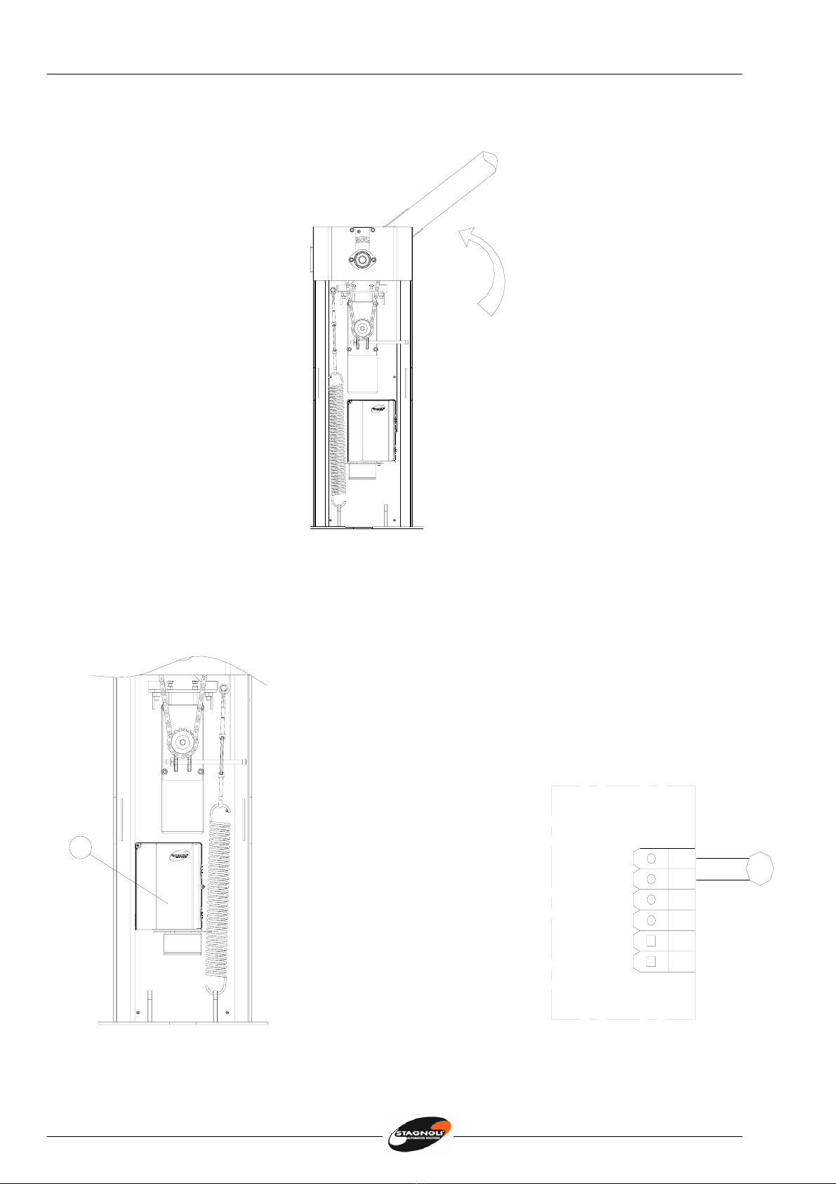
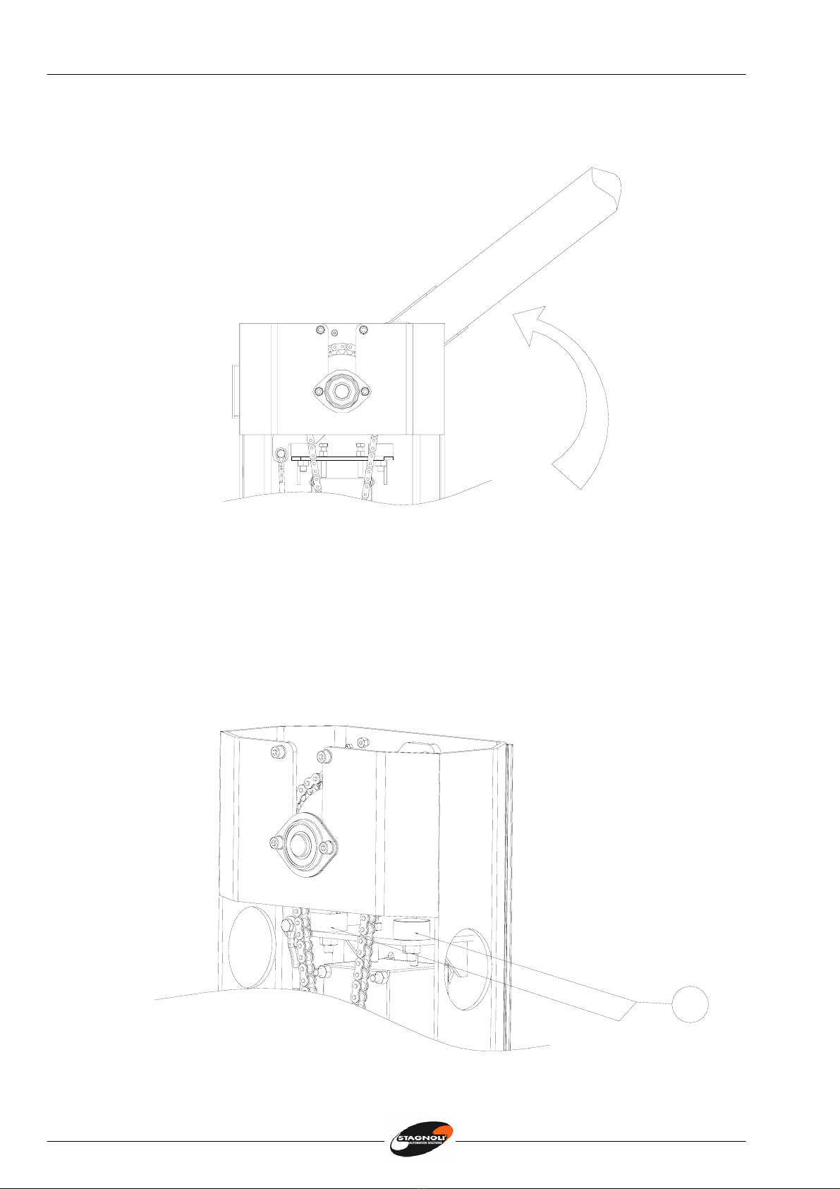
Manovra manuale
•La manovra manuale va eseguita solo a motore
fermo in caso di mancanza di energia elettrica.
•Togliere il cilindro estraibile(1) con la chiave rossa
e con l’ausilio della chiave esagonale(2)
sbloccare il motoriduttore girando in senso
antiorario.
•Per innestare la trasmissione infilare il cilindro con
la chiave rossa inserita e una volta raggiunta la
battuta tenere fermo il cilindro e estrarre la
chiave rossa.
•Attenzione non eseguire la manovra manuale se
non è applicata l’asta alla barriera.
Verifiche preliminari
•Controllare che il terreno abbia le caratteristiche idonee a garantire una sufficiente
tenuta del plinto di cemento , in cui sarà collocata la piastra di fondazione.
•Prevedere il passaggio cavi come da impianto tipo. Il passaggio cavi è situato in
posizione centrale sul fondo della barriera.
•Verificare che non ci siano ostacoli nel raggio d’azione dell’asta che ne impediscano il
movimento.
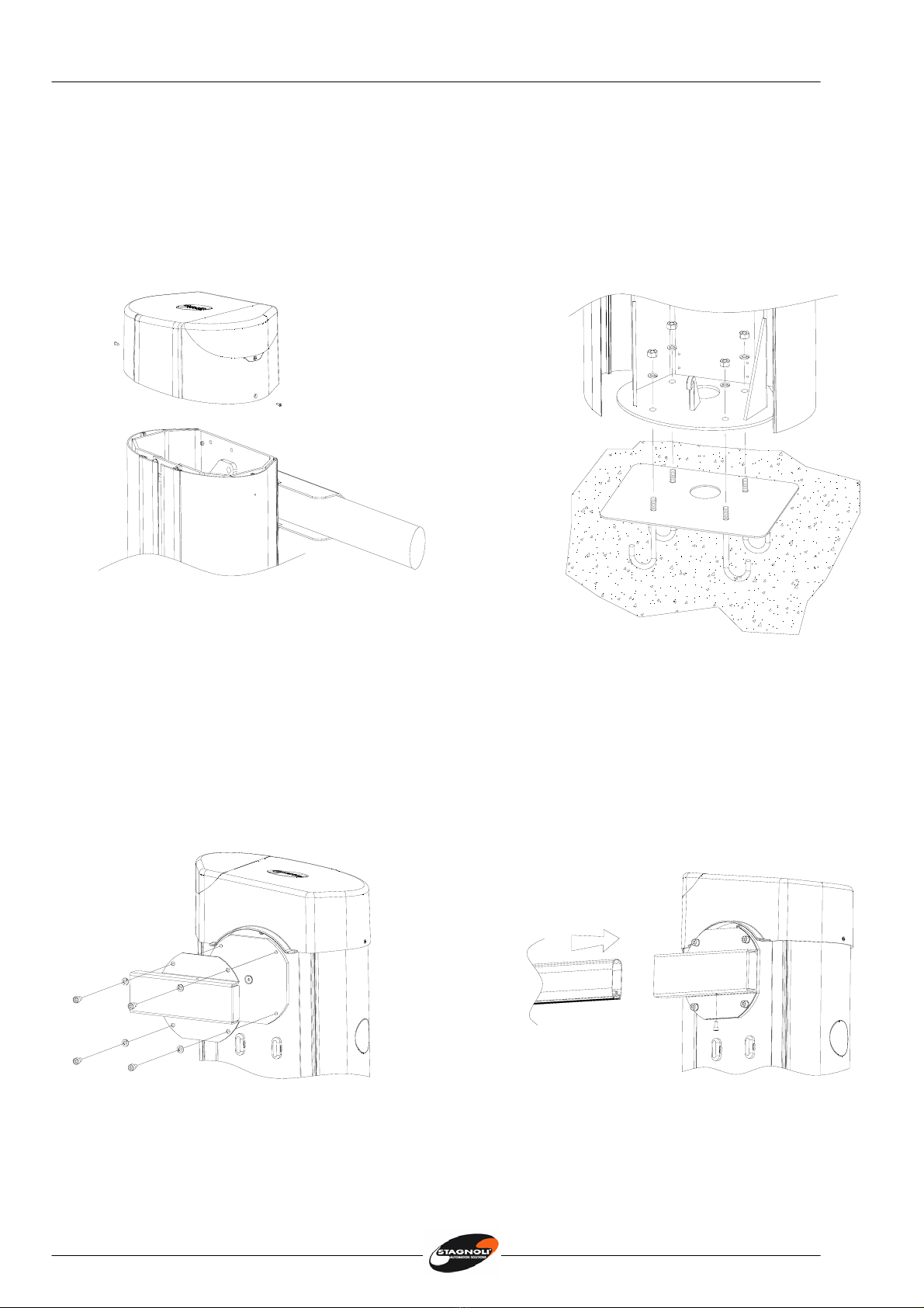
Fissaggio piastra di fondazione (Fig. 2)
La barriera può essere posizionata sia a destra che a sinistra del passaggio, quindi una volta
individuata la giusta posizione procedere nel modo seguente:
•Preparare una piazzola in cemento dove inserire la piastra di fondazione con i relativi
tiranti M10.
•Verificare che la piastra sia perfettamente a bolla, che sia pulita sulla superficie e che i
tiranti filettati siano perpendicolari rispetto alla piastra di fondazione.
Fig. 2
2
1

Istruzioni Instructions Anleitungen
6
Fissaggio barriera
•Togliere il coperchio superiore svitando le viti (Fig. 3).
•Aprire le ante, posizionare la barriera sulla piastra di fondazione facendo corrispondere i
fori con i tiranti filettati e fissare la barriera avvitando i dadi M10 sui rispettivi tiranti (Fig.4).
Fig. 3 Fig. 4
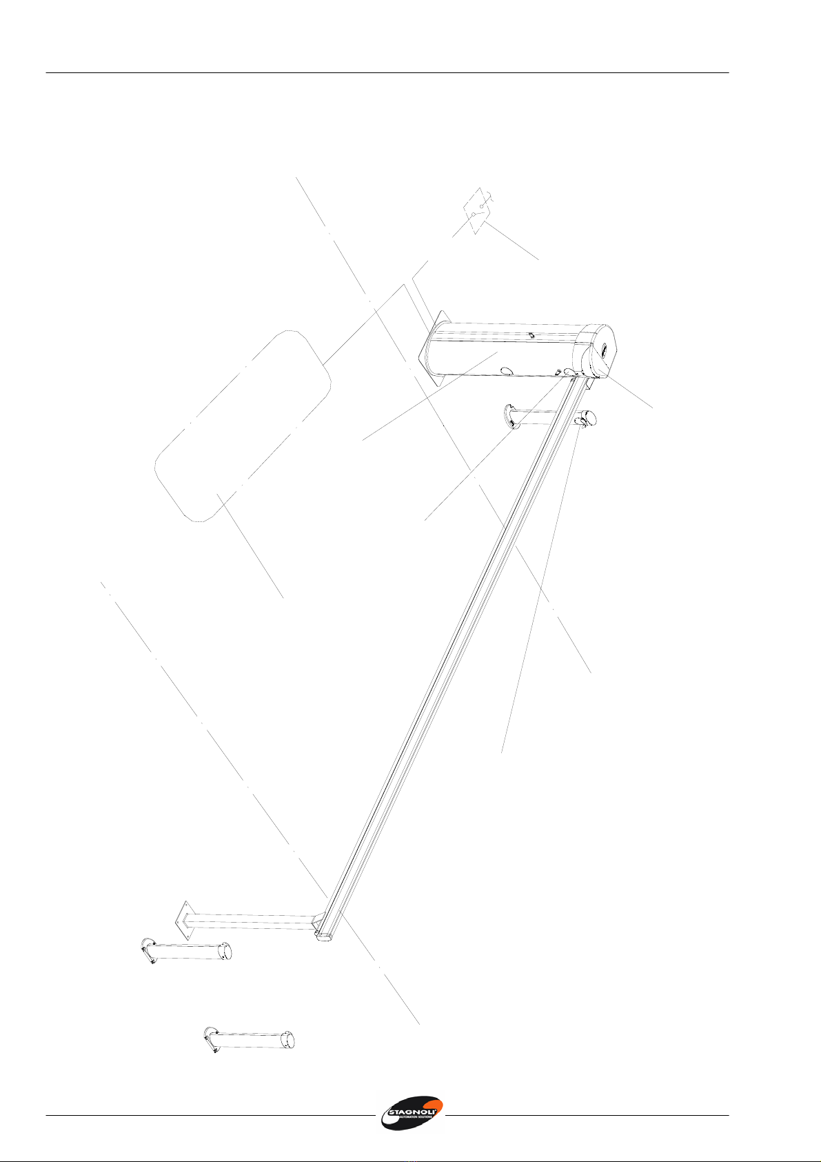
Fissaggio asta
•Fissare la staffa porta-asta, senza avvitare a fondo le viti (Fig. 5).
•Infilare l’asta di sezione rettangolare in battuta sul fermo posteriore, avvitare
definitivamente le 4 viti M8 (Fig.6) e fissare l’asta con la vite M6x12.
Fig. 5 Fig. 6
Istruzioni Instructions Anleitungen
7
Regolazioni asta: l’apertura standard della barriera è in senso antiorario come indicato
in (Fig. 7).
Fig. 7
•Per invertire il senso di apertura, spostare la centrale di comando(1), spostare la
molla nella posizione opposta (Fig.8) e invertire il collegamento del motore
elettrico sulla centrale di comando (Fig.9).
1
8
APM1
9
CHM1
10
LAMP
11
M1
LAMP
12
13
LC
LC
24V 120W
Fig.8 Fig. 9

Istruzioni Instructions Anleitungen
8
•Bilanciare l’asta regolando il tirante filettato, l’asta deve essere in equilibrio nella
posizione di metà corsa (45°) (Fig. 10).
45°
Fig. 10
•Procedere con la programmazione seguendo le istruzioni della centrale di comando e
dopo aver effettuato la programmazione completa aggiustare le posizioni di fine corsa
dell’asta agendo sui rispettivi antivibranti in gomma(1) (Fig. 11).
N.B Attenzione è obbligatorio utilizzare l’appoggio fisso per l’asta.
1
Fig. 11
Istruzioni Instructions Anleitungen
9
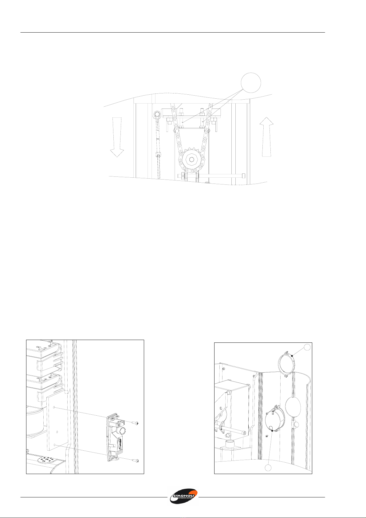
Regolazione tensione catena
Il tensionamento della catena è regolato direttamente in fabbrica, tuttavia se notate che la
catena è allentata, registrarla agendo sulle viti (1) come mostrato di seguito.
1
Allentare
Tensionare
Fig. 12
Manutenzione ordinaria
E’ consigliabile dopo l’installazione, effettuare dei controlli delle parti almeno ogni 6 mesi:
•Verifica del bilanciamento dell’asta (se è necessario bilanciare nuovamente l’asta
regolando il tirante filettato (vedi Fig. 10).
•Verifica del corretto allineamento dell’asta
•Verifica del tensionamento della catena di trasmissione.
Ogni 500,000 manovre eseguire una revisione dei seguenti particolari:
•Sostituzione dei gommini antivibranti.
•Verifica del bilanciamento della molla.
•Verifica del fissaggio a terra del corpo barriera, verifica del fissaggio dell’asta, verifica del
fissaggio del motoriduttore.
•Controllo funzionalità ed efficienza della centrale di comando e delle relative sicurezze.
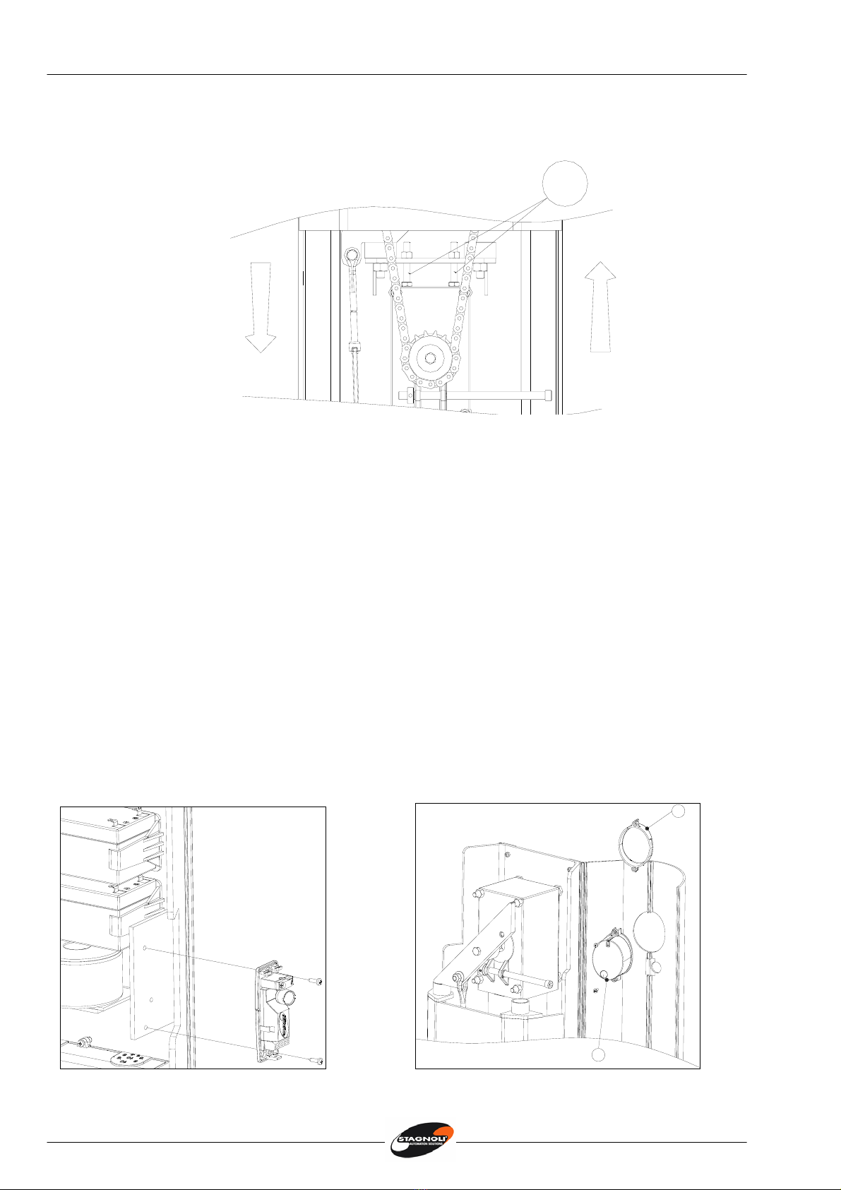
Fissaggio accessori
1
2
Fissaggio fotocellula (opzionale) Fissaggio selettore (opzionale)

Istruzioni Instructions Anleitungen
10
Attention!
•This manual is for qualified installers only and not for the end user. It is the installer’s job to
explain to the user how the automatism works, about possible hazards related to it and the
need for periodical maintenance.
•Installation must be carried out by qualified personnel only, in compliance with current
standards concerning automatic closing mechanisms.
•Daphne has been designed and made specifically to manage the access control of
vehicles. It is therefore forbidden to use the product for different reasons other than those
foreseen in this manual.
•It is forbidden to use it for any other purposes or improperly.
•Use original components only. Stagnoli is not liable for damages if any other components
are used.
•Make absolutely certain the power is disconnected before carrying out any work on the
device.
•Connect the power lead only to supply lines with adequate electrical protection.
•Be particularly careful when evaluating the safety devices to install and their location.
Always install an emergency stop device that will cut power off in the case of necessity

Istruzioni Instructions Anleitungen
11
DAPHNE
Digital or key selector
Barrier
Magnetic loop
Omnipolar switch
Polifemo clolumn-type photocell
Blinker
230V - 50Hz
3x1,5

Istruzioni Instructions Anleitungen
12
DAPHNE’S Technical Details
Tecnical Details DAPHNE 3 m fast
Power Supply 230V~ (50Hz)
Current absorbed Motor (A) 5
Motor Power Supply 24V –––––
Maximum Power Max 120W
Opening Time (sec) 2
Operating Temperature (°C) -20 ↔+60
Duty Cycle (%) intensivo (90)
IP Protection 44
Weight* (Kg) 70
Max. Length of arm (mt) 3
Dimensions
Max. 3000 mm
218
1100
380

Istruzioni Instructions Anleitungen
13
Manual Manoeuvre
•The manual manoeuvring of the arm should
only be carried out when the motor has
stopped due to a cut in the power supply
•Pull off the self releasing cylinder (1) and with
the Alan key (2) unblock the motor turning the
key in an anticlockwise direction.
•To re start the transmission, insert the cylinder
with the red key inside it. Once it has reached
the mechanical stop keep the cylinder still and
pull the red key out.
•Warning! Do not carry out the manual
manoeuvring if the arm is not fixed to the
motor.
Preliminary Checks
•Make sure that the ground is ideal for holding the cement base, in which the foundation
plate will be mounted.
•Make sure to foresee the passage of the cables as in the ideal set-up. The cable passage
is situated in a central position on the back of the barrier.
•Make sure that there are no obstacles in the way of the arm’s radius that could stop it’s
movement.
Fixing of the foundation plate (Fig. 2)
The barrier can be positioned either to the right or to the left of the passage. Therefore, once
decided the correct position proceed to the following steps:
•Prepare a cement base where you can insert the foundation plate with the relative rods.
•Make sure that the plate is perfectly flat, that it’s surface is perfectly clean and that the
rods are precisely perpendicular to the ground.
Fig. 2
2
1
Istruzioni Instructions Anleitungen
14
Fixing the barrier
•Take the top cover off by unscrewing the screws (Fig. 3).
•Open the barrier wings, position the barrier on the foundation plate making sure that the
lower holes correspond to the screwable rods and screw everything in place with the M10
nuts. (Fig.4).
Fig. 3 Fig. 4
Fixing in the aluminium bar
•Fix down the bar holder bracket without wholly tightening down the screws (Fig. 5).
•Slide the square barrier arm into the bracket from the opposite side of its lid, screw in
tightly the four M8 screws (Fig. 6) and fix the boom with the M6x12 screw.
Fig. 5 Fig. 6

Istruzioni Instructions Anleitungen
15
Adjusting the arm: the standard opening of the barrier is in an anticlockwise direction as in
(Fig. 7).
Fig. 7
•To invert the opening direction of the arm, move the spring to the opposite position (Fig.8)
and invert the connection of the electric motor to the control panel (Fig.9).
1
8
APM1
9
CHM1
10
LAMP
11
M1
LAMP
12
13
LC
LC
24V 120W
Fig.8 Fig. 9
Istruzioni Instructions Anleitungen
16
•Balance the barrier’s arm adjusting the screwable rods. The arm must be in equilibrium in
the half way position (45°) (Fig. 10).
45°
Fig. 10
•Proceed with the programming of the control panel following the specific electrical
instructions and after having carried out the complete programming regulate the position
of the arm’s limit switches, lowering or raising the relative rubber antivibration drums (1)
(Fig. 11).
N.B Warning it is compulsory to use the fixed support for the bar.
1
Fig. 11
Istruzioni Instructions Anleitungen
17
Adjusting the chain’s tension
The chain’s tension is adjusted directly in the warehouse, however, if you notice that the chain is
slightly slack, adjust, using screws (1) as in example (Fig. 12).
1
Slackening
Tightening
Fig. 12
Ordinary Maintenance
It is advisable, after installation, to carry out checks on the moving parts, at least every 6 months:
•Check the balance of the arm ( if necessary rebalance the arm adjusting the screwable
rods) (see Fig. 10).
•Check the correct alignment of the arm.
•Verifying the tension on the transmission chain.
Every 500,000 manoeuvres carry out a revision of the following parts.
•Replace the rubber antivibration drums
•Check that the spring is balanced
•Check that the body of the barrier is securely grounded, check that the arm is still tightly
attached and check that the motor is still securely fixed.
•Check the relative functionality and efficiency of the control panel and the safety
accessories.
Fixing accessories
1
2
Fixing the photocell (optional) Fixing the digital or key pad (optional)

Istruzioni Instructions Anleitungen
18
Achtung!
•Das vorliegende Handbuch richtet sich ausschließlich an das technische Personal mit
entsprechender Befähigung zur Installation und nicht an den Endanwender; es obliegt
dem Installateur den Verbraucher über die Benutzung des Automatismus zu informieren,
sowie über die möglichen aus dem Gebrauch des Gerätes resultierenden Gefahren und
über die Notwendigkeit regelmäßige Wartung durchzuführen.
•Die Installation ist ausschließlich durch qualifiziertes Fachpersonal, gemäß den
einschlägigen, den Schließtorautomatismus betreffenden gesetzlichen Normen
durchzuführen.
•DAPHNE wurde eigens für die Regelung von Fahrzeugdurchfahrten entwickelt; eine
zwecksentfremdete oder nichtsachgemäße Verwendung des Produktes ist daher
untersagt.
•Es sind ausschließlich Originalteile zu verwenden. Die Herstellerfirma Stagnoli übernimmt
keine Haftung für Schäden, die durch Gebrauch der nichtbestimmungsgemäßen
Ersatzteile verursacht werden.
•Vor jedem Eingriff ins Gerät ist sicherzustellen, daß die Stromversorgung unterbrochen
wurde.
•Der Spannungskabel ist nur an ein Stromversorgungsnetz mit entsprechender elektrischen
Sicherung anzuschließen
•Die zu installierenden elektrischen Sicherheitsvorrichtungen, wie auch der Ort, an dem sie
angebracht werden sollen, ist mit Bedacht zu wählen. Es muß unbedingt eine
Trennvorrichtung eingeschaltet werden, die - falls erforderlich - eine Stromabschaltung
(Not-Aus-Betrieb) einleiten kann.

Istruzioni Instructions Anleitungen
19
230V - 50Hz
3x1,5
DAPHNE 24 V: Anlagesystem
Lichtschranke am Pfosten Poliferno
Blinkleuchte
Allpoliger Schalter
Schlüssel- oder Digitalschalter
Schranke
Magnetischer Sensor

Istruzioni Instructions Anleitungen
20
Technische Merkmale Daphne
Technische Daten DAPHNE 3m
Stromversorgung 230V~ (50Hz)
Stromaufnahme (A) 5
Betriebsspannung 24V –––––
Motorleistung max. 120W
Laufzeit Öffnung (Sek.) 2
Betriebstemperatur (°C) -20 ↔+60
Einschaltdauer (%) intensiv (90)
Schutzgrad IP 44
Gewicht* (Kg) 70
Baumlänge max. (m) 3
Abmessungen
Max. 3000 mm
218
1100
380
Table of contents
Languages:
Other Stagnoli Control System manuals


Popular Control System manuals by other brands


Chamberlain
Chamberlain GAROG TST-2 Operational description

Siemens
Siemens SINUMERIK 808D user manual

Ecolab
Ecolab Advanced Laundry Installation & operation manual

SENSTAR
SENSTAR 100 installation guide

IGM Professional
IGM Professional Odyssey BAYLOAMS20 installation guide

LBA GROUP
LBA GROUP LBA 12 IRREVERSIBLE operating instructions


