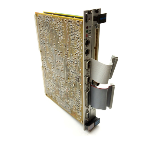
Xycom XVME-530 User manual

Artisan Technology Group is your source for quality
new and certied-used/pre-owned equipment
• FAST SHIPPING AND
DELIVERY
• TENS OF THOUSANDS OF
IN-STOCK ITEMS
• EQUIPMENT DEMOS
• HUNDREDS OF
MANUFACTURERS
SUPPORTED
• LEASING/MONTHLY
RENTALS
• ITAR CERTIFIED
SECURE ASSET SOLUTIONS
SERVICE CENTER REPAIRS
Experienced engineers and technicians on staff
at our full-service, in-house repair center
WE BUY USED EQUIPMENT
Sell your excess, underutilized, and idle used equipment
We also offer credit for buy-backs and trade-ins
www.artisantg.com/WeBuyEquipment
REMOTE INSPECTION
Remotely inspect equipment before purchasing with
our interactive website at www.instraview.com
LOOKING FOR MORE INFORMATION?
Visit us on the web at www.artisantg.com for more
information on price quotations, drivers, technical
specications, manuals, and documentation
Contact us: (888) 88-SOURCE | sales@artisantg.com | www.artisantg.com
SM
View
Instra

0
1993
XYCOM,
INC.
Printedin the United States
of
America
Part
Number 74530-001
B
ANALOG
OUTPUT
MODULE
74530-001
B
XYCOM
750
North
Maple
Road
Saline,
Michigan
48176-1292
734-429-4971
(phone)
734-429-1010
(fax)
Artisan Technology Group - Quality Instrumentation ... Guaranteed | (888) 88-SOURCE | www.artisantg.com

XYCOM
REVISION RECORD
Revision Description Date
I
A
B
~
Manual Released
01/85
Incorporated
PCN's
087 and 094 07/93
,
Copyright Information
This
document
is
copyrightedby Xycom Incorporated(Xycom)andshallnot be reproduced
or
copiedwithout
expressedwritten permissionfromXycom.
Theinformationcontainedwithinthisdocumentis subjecttochangewithoutnotice. Xycomdoesnotguarantee
the accuracy
of
the informationand makes no commitmenttowardkeepingit up
to
date.
Addresscomments concerning
this manual
to:
TechnicalPublicationsDept.
EOzMmleRoad
Saline,Michigan 48176
Part
h'umber:
74530-001
B
Artisan Technology Group - Quality Instrumentation ... Guaranteed | (888) 88-SOURCE | www.artisantg.com

XVME-530 Manual
October, 1984'
TABLE OFCONTENTS
CHAPTER
1
2
3
1.1
1.2
1.3
1.4
1.5
2.1
2.2
2.3
2.4
2.4.1
2.4.2
2.4.3
2.4.4
2.4.5
2.5
2.6
3.1
3.2
3.3
3.4
3.5
3.5.1
3.5.2
3.6
A
B
C
D
TITLE
INTRODUCTION
Introduction
How This Manual
is
Organized
Overview
Features
of
XYCOM's Standard 1/0 Architecture
Specifications
INSTALLATION
General
System Requirements
Location of Components Relevent
to
Installation
Jumpers/Switches
Base
Address Switches
Supervisory/Non-Privileged
Mode Selection
Address Modifier Reference
BGxIN/BGxOUT and IACKIN/IACKOUT Daisy Chains
Output Jumpering
Analog Output Connections
Module Installation
PROGRAMMNG
Introduction
Base Addressing
1/0
Interface Block
Status/Control Register
Data Register
D/A Conversions
Digital Data Format
Calibration
APPENDICES
XYCOM Standard 1/0 Architecture
VMEbus Connector/Pin Description
Schematics and Diagrams
Quick Reference Guide
PAGE
1-1
1-1
1-1
1-3
1-4
2-1
2-1
2-1
2-3
2-4
2-5
2-5
2-5
2-6
2-7
2-7
3-1
3-1
3-3
3-3
3-5
3-5
3-5
3-6
A- 1
B-
1
c-
1
D- 1
i
Artisan Technology Group - Quality Instrumentation ... Guaranteed | (888) 88-SOURCE | www.artisantg.com

XVME-530 Manual
October, 1984
TABLE OF CONTENTS (continued)
LIST
OF
FIGURES
FIGURE TITLE PAGE
Block Diagram
of
the Analog Output Module 1-2
1-1
2-
1
2-2
2-3
2-4
AOUT Jumpers, Address Switches, and Connectors
Address Switches
Buffer Jumper Configuration Diagram
VMEbus Chassis
2-2
2-5
2-6
2-9
AOUT
1/0
Interface Block
Status/Control Registers
Data Port (address
=
base+82H)
3-2
3-3
3-5
3-
1
3-2
3-3
A- 2
A-4
A-
6
A-
8
A-10
A-
1
A- 2
A-3
A-4
A-5
64K Short 1/0 Address Space
XVME 1/0 Module Address Map
Module LED Status
Status Register Bit Definitions
Intelligent and Non-Intelligent Kernels
LIST OF TABLES
PAGE
TABLE TITLE
1-1
Analog Output Module Specifications 1-4
AOUT Jumper/Switch List
Base Address Switches
Privilege Options
Address Modifier Code Options
Jumper Configurations for Output Mode Options
Output Connector
JK
1
2-3
2-4
2-5
2-5
2-6
2-7
2-1
2-2
2-3
2-4
2-5
2-6
3-
1
3-2
3-3
3-4
3-5
3-6
LED Status
Unipolar Modes (Straight Binary Encoding)
Bipolar Voltage Mode (Offset Binary Encoding)
Channel Zero Adjust Potentiometers
Channel Gain Adjust Potentiometers
Pot
en
t
io
m
et
er Ad
j
ust
men
t
s
3-4
3-6
3-6
3-7
3-7
3-8
A-
1
Module I.D. Data A-5
PI
-
VMEbus Signal Identification
PI Pin Assignments
P2
-
VMEbus Signal Definitions
P2 Pin Assignments
B-
1
B-2
B-3
B-4
8-1
8-5
B-6
B-6
ii
Artisan Technology Group - Quality Instrumentation ... Guaranteed | (888) 88-SOURCE | www.artisantg.com

XVME-530 Manual
October, 1984
Chapter
1
INTRODUCTION
1.1
INTRODUCTION
The XVME-530 Analog Output Module (hereafter referred to
as
AOUT)
is
a
powerful
D/A module which can generate eight 12-bit resolution analog signals. Output can be
either voltage
or
current. The following output voltage ranges are jumper-selectable:
0-5V,
0
to
lOV,
+2.5V,
+5V,
+lOV.
The jumper-selectable current range is 4-20 mA.
The eight outputchannels areopticallyisolated (300V) from the digital logic.
The gain and offset errors are both adjustable to zero, and the maximum overall error
is
0.5
LSB.
1.2
HOW
THIS
MANUAL
IS
ORGANIZED
This chapter provides
a
functional overview
of
the AOUT and presents the features of
XYCOM's Standard
1/0
Architecture. Operational aspects of the AOUT are then
explained in the following fashion:
Chapter 2
-
Installation
--
Presents information required
to
position the jumpers
and switches on the AOUT, and then install
it
on
a
VMEbus chassis.
Chapter
3
-
Programming
--
Presents information required to program the
AOUT and output analog signals.
The appendices
at
the rear
of
this manual provide information on XYCOM's Standard
1/0
Architecture, VMEbus connector/pin description, module schematics, and
a
quick
reference guide
to
the AOUT's jumpers and registers.
1.3
OVERVIEW
Figure
1-1
shows an operational block diagram
of
the VMEbus compatible Analog
Output module (AOUT).
1-1
Artisan Technology Group - Quality Instrumentation ... Guaranteed | (888) 88-SOURCE | www.artisantg.com

XVME-530 Manual
October,
1984
I
CONNECTOR
J1
1
Figure
1-1.
Block Diagram
of
the Analog Output Module
As can be seen from Figure
1-1,
the AOUT consists
of
the Non-Intelligent Kernel
which
is
standard for XYCOM's non-intelligent VMEbus modules, and application
circuitry specific
to
the AOU'T.
1.3.1
XYCOM
Non-Intel-ent
Kernel
The Non-Intelligent Kernel
is
basically the interface
to
the VMEbus.
It
provides all
the necessary circuitry to receive and generate the signals required by the VMEbus
specification for
a
16-bit slave. By simply adding the application circuitry (in this
1-2
Artisan Technology Group - Quality Instrumentation ... Guaranteed | (888) 88-SOURCE | www.artisantg.com

XVME-530 Manual
October, 1984
case
D/A circuitry),
a
VMEbus module
is
complete. The Non-Intelligent Kernel has the
following features:
0
Control and Address Buffers
0
Address Decode circuitry
0
Control/Status Register
0
Module identification information
0
Pass
and
Fail
LED
indicators
The XYCOM Non-Intelligent Kernel
is
described in further detail in Appendix A.
1.3.2
Application Circuitry
As Figure
1-1
shows, the application circuitry consists primarily of the following:
0
0
0
0
0
8
D/A converters which perform 12-bit resolution D/A conversions
Data latch to store the digital data
to
be converted
to
analog
Channel latch
to
select the output channel over which the data will be
output
Optical isolator
to
isolate between the digital and analog circutry
Timing controller to transfer digital information across the optical isola-
tion boundary
to
the
D/Afs
1.4
FEATURES
OF
XYCOM'S
STANDARD
I/O
ARCHITECTURE
The
AOUT
and all XYCOM
1/0
modules conform
to
the unique XYCOM VMEbus
Standard I/O Architecture. This architecture
is
intended to make the programming of
XYCOM VMEbus
1/0
modules simple and consistent. The following features apply to
the operation
of
the AOUT.
0
Module Address Space
-
The AOUT and all VMEbus modules
are
controlled
by writing
to
addresses within the 64K Short 1/0 Address space. A VMEbus
module can be jumpered
to
occupy any of the 64 available
1K
blocks.
This block, known
as
the
1/0
Interface Block, contains
all
of
the module's
programming registers, and ID data. Within the 1/0 Interface Block, the
offsets are standardized
so
that the user may expect
to
find the same
registers and data
at
the same offsets across the entire XYCOM VMEbus
line.
Module Identification
-
The AOUT has I.D. information which provides
its
name, model number, manufacturer and revision level
at
a
location that is
consistent with other XYCOM 1/0 modules.
0
Status/Control Register
-
This re ister
is
always located
at
address
Base+81H, and the lower four bits
7
two Test Status bits, and
a
red and
green LED bit) are standard from module to module.
0
A detailed description of XYCOM
1/0
Architecture
is
presented in Appendix A
at
the
rear
of
this manual.
1-3
Artisan Technology Group - Quality Instrumentation ... Guaranteed | (888) 88-SOURCE | www.artisantg.com

XVME-530 Manual
October, 1984
1
5
SPECIFICATIONS
Table
1-1.
Analog Output Module Specifications
Characteristic
ANALOG OUTPUTS
Number Available
Optical Isolation
Monotonicity
Accuracy
Resolution
Overall Error
(1)
Conversion Time(2)
Settling Time
(to
.01%,
into
Voltage Output Char
act
eri
stics
resistive load)
Ranges
Output Current
Offset T.C.
Gain T.C.
Range
Offset T.C.
Gain T.C.
Load Resistance Range
Load Regulation
Digital Input Coding
Reset
Current Loop Characteristics
Electrical
Power Requirements
Board Dimensions
Temperature
Operating
Non-Operating
~~~
-
Specification
8
300V
Guaranteed
12bits
t0.5
LSB +.0122%
42
usec
30
usec. max. (current mode)
8
usec. max. (voltage mode)
-
0
to
5V,
0
to
lOV,
-
+2.5V,
-
+5V,
+1OV
5mA mino
@
+1OV
30
ppm/oC (Gpolar voltage mode)
15
ppm/oC (unipolar voltage mode)
50
PPm/
c
4-20mA
50
to
525 ohms
.808 ppm/Ohm
BIN, OBN
All DACs are r-3et
to
OOOOH
at
power-up
or system reset
5V
+5%,
Typ. 2.6
A
(with outputs
at
full
scale
in 4:20mA mode)
NEXP Board Size (160mm x 233.4mm)
0
to
65OC
L32O
to
149'F)
-40'
to
85
C
(-40'
to
158'F)
(1)
Overall error
is
specified with gain and offset trimmed and
is
defined
as
the deviation from
a
straight line passing through the end points of the
range. It
is
expressed in terms of bits and in terms of the deviation
as
a
percent of the full scale range (Le.,
-
+.5
LSB
is
-
+0.0122% FSR of
a
-lOV
to
+~OV
range).
Conversion time
is
defined
as
the time required
to
transfer 12 bits
of
data across the optically-coupled interface.
It
is
measured from the
time the
low
byte
is
written to when the analog output first starts to
change.
(2)
1-4
Artisan Technology Group - Quality Instrumentation ... Guaranteed | (888) 88-SOURCE | www.artisantg.com

XVME-530 Manual
October, 1984
~ ~~~
Characteris
t
ic
Humidity
Table
1-1.
Analog Output Module Specifications (continued)
Specification
5
to 95%
RH
non-condensing
(Extreme
low
humidity conditions may
require special protection against
static
discharge.)
Altitude
Operating
Non-0per
a
t
ing
Vibration
Operating
Non-0per
a
ting
Shock
Operating
Non-Operating
Sea-level
to
10,000
ft.
(3048 m)
Sea-level to
50,000
ft.
(15240
m)
5
to
2000
Hz
.015
in peak-to-peak displacement
2.5
g
peak (maximum)acceleration
5
to
2000
Hz
.030
in peak-to-peak displacement
5.0
g
peak (maximum)acceleration
30
g
peak acceleration,
11
msec duration
50
g
peak acceleration,
11
msec duration
1-5
Artisan Technology Group - Quality Instrumentation ... Guaranteed | (888) 88-SOURCE | www.artisantg.com

Artisan Technology Group - Quality Instrumentation ... Guaranteed | (888) 88-SOURCE | www.artisantg.com

XVME-530 Manual
October,
1984
Chapter
2
INSTALLATION
2.1
GENERAL
This chapter provides the information
to
configure the AOUT prior
to
installation in
a
VMEbus backplane card
cage,
and presents the installation procedure.
2.2
SYSTEM
REQUIREMENTS
The AOUT
is
a
double-height VMEbus compatible module.
properly installed in
a
VMEbus backplane cardcage.
ments for operation of the AOUT are one
of
the following:
To operate
it
must be
The minimum system require-
A)
0
A host processor properly installed on the samebackplane.
0
A
properly installed controller subsystem.
An
example of such
a
controller
subsystem
is
the XYCOM XVME-010 System Resource Module
(SRM).
B)
0
A
host processor which incorporates
an
on-board controller subsystem.
2.3
LOCATION
OF
COMPONENTS RELEVANT
TO
INSTALLATION
The jumpers, Address Switches, and connectors on the AOUT are illustrated
in
Figure
2-1.
2-
1
Artisan Technology Group - Quality Instrumentation ... Guaranteed | (888) 88-SOURCE | www.artisantg.com

XVME-530
Manual
October,
1984
m
c
3
3
r
lm'
C
C
I
c
Figure
2-1.
AOUT Jumpers, Address Switches, and Connectors
2-2
Artisan Technology Group - Quality Instrumentation ... Guaranteed | (888) 88-SOURCE | www.artisantg.com

AVME-530 Manual
October, 1984
2.4
JUMPERS/SWITCHES
Prior
to
installing the AOUT,
it
will be necessary to configure several jumper/switch
selectable options. These options fall into two categories: VMEbus-related options
and Analog-to-Digital conversion options.
VMEbus Options
e
e
Module base address, selected by switches
1-6
of the Address Switches.
Privilege level required
to
access
the module, selected by switch
8
of
the
Address Switches.
Analog
to
Digital Conversion Options
e
8
jumper blocks (labeled
J5
through 512). Each jumper bank selects from
the following available output voltage and current ranges:
4-20mA current loop
0-
i
OV
0-5V
-
+1ov
-
+5V
-
+2.5V
i
Jumper/Switch
I
I
31
J2B
J3,
J4
J5
J6
J7
58
J9
J10
J11
J12
Address Switches
Table 2-1.
AOUT
Jumper/Switch List
Use
Not
used
on
the AOUT.
Jumper 32 must be in the
rrBrt
position for proper
module
operation.
Not
used on the AOUT.
One jumper block per output channel.
Address and Address Modifier compare switches.
2-3
Artisan Technology Group - Quality Instrumentation ... Guaranteed | (888) 88-SOURCE | www.artisantg.com

XVME-530 Manual
October, 1984
Switch
6
5
4
3
2
1
2.4.1
Base
Address
Switches
Address Bit
A1
5
A14
A13
A12
A1
1
A10
The AOUT has been constructed in accordance with
XYCOM's
Standard
1/0
Archi-
tecture
(see
Appendix A for
a
detailed description). As such,
it
can occupy any one
of
64
1K
blocks
of
memory within the 64K VMEbus Short
1/0
Address Space. The
particular
1K
block it shall reside in
is
selected by configuring the AOUT's "Base
Address'! equal to the beginning address
of
that block. The Base Address
is
selected by
configuring 'switches 1-6
of
the Address Switches
(see
Figure 2-21,
as
shown in Table
2-2.
NOTE
Switch position
8
must be
set
to the llClosedtl
position. Switch
7
is described in Section 2.4.2.
678
Figure 2-2. Address Switches
Table 2-2. Base Address Switches
NOTE
"OPEN" position equals logic
1,
closed equals logic
0.
2-4
Artisan Technology Group - Quality Instrumentation ... Guaranteed | (888) 88-SOURCE | www.artisantg.com

XVME-530 Manual
October, I984
Switch
7
Closed
2.4.2
Supervisor/Non-Privileged
Mode
Selection
Privilege Mode Selected
Supervisory or Non-Privileged
The AOUT can respond only to Short 1/0
accesses.
However,
it
can be configured to
respond
to
only Supervisory
access,
or to both Non-Privileged and Supervisory
accesses,
by selecting the position
of
Switch
7
(see
Figure
2-3),
as
shown in Table 2-3
below. Available AM codes are all Short 1/0 codes.
Short
I/
0
Table 2-3. Privilege Options
Switches Jumper Address Modifier
Code
7
8
32
AOUT
will
respond
to
Closed Closed
B
29H
or 2DH
Open Closed
B
2DH only
2.4.3
Address Modifier Reference
2.4.4
BGxIN/BGxOUT
and
IACKIN/IACKOUT Daisy Chains
The Data Bus Arbitration signals BGxIN and BGxOUT (where lfxllcan be
a
number
0-3
to represent the three levels of arbitration) are not used by the AOUT, and are
hardwired together on the module
to
allow the BGxIN/BGxOUT Daisy Chain to pass
through the backplane slot occupied by the AOUT. In each slot of the VMEbus
backplane, there are four
sets
of jumpers shorting the signal BGxIN to BGxOUT
(x=G
thru
3).
Since these signals are already hardwired on the AOUT,
it
is not necessary to
insert these VMEbus jumpers on the slot occupied by the AOUT.
In addition, IACKIN/IACKOUT
are
hardwired together on the AOUT module.
2-
5
Artisan Technology Group - Quality Instrumentation ... Guaranteed | (888) 88-SOURCE | www.artisantg.com

XVME-530 Manual
October,
1984
Mode Chosen
2.4.5
Output
Jumpering
~~~
Jumpers
(all
other output jumpers should be removed)
The AOUT’s
8
outputs can each
be
individually configured in one of
6
different modes
by jumpering the operational amplifier buffer on the output
of
each channel into
different coniigurations. Eacn configuration
is
selected by placing jumpers across
certain points labeled
A,
B,
C,
D,
E,
F,
H,
J,
K,
and
L,
on the AOUT circuit board.
The diagram format below will be used
to
represent the jumper banks
J5-Jl2.
The
jumper configurations for each analog output option are listed in Table
2-5.
0-0
0-0
0-0
0-0
0-0
0-0
0-0
0-0
0’70
0-0
Figure
2-3.
Output Jumper Configuration Diagram
The following
table
lists
the jumper configuration unique to each mode.
Table
2-5.
Jumper Configurations for Output Mode Options
NOTE
The
AOUT
will
be
shipped
to
the customer in the
4-20mA
output mode.
2-6
Artisan Technology Group - Quality Instrumentation ... Guaranteed | (888) 88-SOURCE | www.artisantg.com

XVME-530 Manual
October, 1984
2.5
ANALOG OUTPUT CONNECTIONS
The module is capable
of
providing
8
separate analog outputs. The outputs are
accessible on the front edge
of
the board in the form of one
34
pin mass termination
header. The connector
is
labeled
JK1
(see Figure 2-11. The following table shows the
pin designations for
JK
1.
Table 2-6. Output Connector
JK1
JK
1
Pin Signal Pin Signal
1
2
3
4
5
6
7
8
9
10
11
12
13
14
15
16
17
18
19
20
21
22
23
24
25
Chan.
0
Gnd
Chan.
0
Vout
Chan.
0
IOUT-
Chan.
0
IOUT+
Chan.
I
Gnd
Chan.
I
Vout
Chan.
1
IOUT-
Chan.
1
IOUT+
Chan. 2 Gnd
Chan.
2
Vout
Chan. 2 IOUT-
Chan. 2 IOUT+
Chan.
3
Gnd
Chan.
3
Vout
Chan.
3
IOUT-
Chan.
3
IOUT+
Chan. 4 Gnd
Chan.
4
Vout
Chan.
4
IOUT-
Chan.
4
IOUT+
Chan.
5
Gnd
Chan.
5
Vout
Chan.
5
IOUT-
Chan.
5
IOUT+
Chan.
6
Gnd
2.6
MODULE INSTALLATION
26
27
28
29
30
31
32
33
34
Chan.
6
Vout
Chan. 6 IOUT-
Chan.
6
IOUT+
Chan. 7 Gnd
Chan. 7 Vout
Chan. 7 IOUT-
Chan.
7
IOUT+
Gnd
Gnd
The
XY
COM VMEbus modules can accommodate typical VMEbus backplane construc-
tion. Figure 2-4 shows
a
standard VME chassis and
a
typical backplane configuration.
There are two rows of backplane connectors depicted (i.e., the PI backplane and the
P2 backplane).
2-7
Artisan Technology Group - Quality Instrumentation ... Guaranteed | (888) 88-SOURCE | www.artisantg.com

XVME-530 Manual
October, 1984
2.6.1
Installation
Procedure
CAUTION
Do
not attempt
to
install or remove any boards
before turning off the power
to
the bus and all
related external power supplies.
Prior
to
installing
a
module, determine and verify
all relevant jumper configurations and all connec-
tions to external devices or power supplies. (Please
check the jumper configuration with the diagram
and lists in the manual.)
To
install
a
board in the cardcage, perform the following steps:
1)
Make certain that the particular cardcage slot you are going
to
use
is
clear
and accessible.
2)
Center the board on the plastic guides
so
that the solder side is facing
to
the left and the component side
is
facing
to
the right (refer to Figure
2-4).
Push the card slowly toward the rear of the chassis until the connectors
engage (the board should slide freely in the plastic guides).
Apply straight-forward pressure
to
the two handles on the outer edge of
the board until the connectors are fully engaged and properly seated.
3)
4)
NOTE
It should not be necessary
to
use excess pressure or
force to engage the connectors. If the board does
not properly connect with the backplane, remove
the module and inspect all connectors and guide
slots for possible damage or obstructions.
5)
Once the board is properly seated,
it
should be secured by tightening the
two machine screws
at
the extreme top and bottom of the board.
2-8
Artisan Technology Group - Quality Instrumentation ... Guaranteed | (888) 88-SOURCE | www.artisantg.com

XVME-530
Manual
October,
1984
SRM
MUST
GO
‘P1’
BACKPLANE
IN SLOT
1
\
-SLOT
SOLDER
SIDE
I
I
COMPONENT SIDE
\
‘P2’
SACKPLANE
Figure
2-4. VMEbus Chassis
2-9
Artisan Technology Group - Quality Instrumentation ... Guaranteed | (888) 88-SOURCE | www.artisantg.com
Table of contents
Other Xycom Control Unit manuals

Xycom
Xycom XVME-956 Series User manual

Xycom
Xycom XVME-212 User manual

Xycom
Xycom XVME-653 User manual

Xycom
Xycom XVME-976 User manual

Xycom
Xycom XVME-601 User manual

Xycom
Xycom XVME-678 User manual

Xycom
Xycom XVME-675 User manual

Xycom
Xycom XVME-100 User manual

Xycom
Xycom XVME-951 User manual

Xycom
Xycom XVME-682 User manual
Popular Control Unit manuals by other brands

SMC Networks
SMC Networks VP300 Series manual

Enclustra
Enclustra Mercury+ KX2 user manual

Honeywell
Honeywell LYNXDM-GSM Installation and setup guide

CARLO GAVAZZI
CARLO GAVAZZI SMXL20 instruction manual

Woodward
Woodward Vertex product manual

Victaulic
Victaulic FireLock NXT 764 Series Replacement instructions