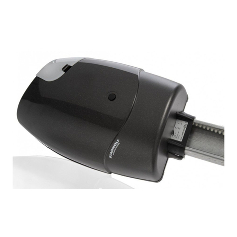
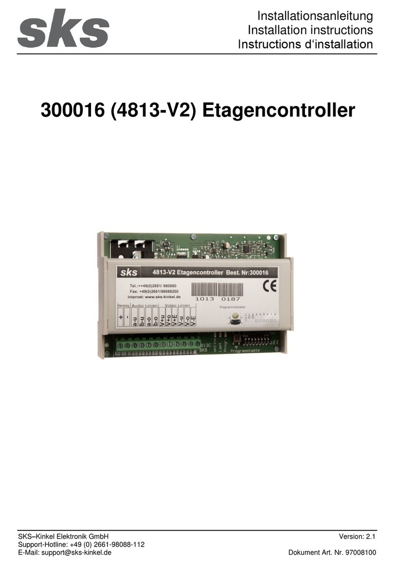
Stagnoli D241000 User manual

0241000
ISTRUZIONI CENTRALE
DI
COMANDO PER BARRIERA
CENTRAL UNIT CONTROLLER INSTRUCTIONS FOR BARRIER .
-
„
--~
~~
-·~
~~
··.1
Q::S]
l
Moving ldeas.

OPERATING INSTRUCTIONS
FOR
INSTALLATION AND
SETIINGS
lnstructions for use only tor protessional installer. Before installing, please read carefully instructions. Uncorrect use
of
the product or a con-
nection failure could atfect
1he
correc1 working and the end user's
safe1y.
TECHNICAL
DATA
Power Supply : 230V -±10% -50Hz•;
lntegrated Receiver: 433MHz: 76 trasmettitori MAX;
Anti-crushing Electronic Device: amperometric + encoder
INTENDED USE
Working Temperature: -20°C I +60°C;
MAX Power Output External Flash:
24V-
-25W;
Accessories Supply:
24V-
-25W;
Tile Skyga1es 0241000 is the central unit controller designed to manage road barriers DAPHNE 24V and
i1s
accessories. Made only with grade
materials, it's designed to have low absorption when not working, and allows a net energy saving. Particular attention was paid to professionals
making easy the settings
of
unit controller, 1hanks to a multilanguage display.
PARTS DESCRIPTlON
11
1 Line tuse: 230V (T2,5A 5x20) ·
eh
2 Terminal block for connection the line input to the transformer.
3 Primary 1ransformer: 230V, secondary
24V-,
110VA
4 Supply input:
24V-
5 - Fuses
a.
accessories output (F2A
5x20J
b. motor (F10A 5x20)
c. output flashing and LED strip (F2A 5x20)
6- Keys tor Menu navigation
7- Display LCD 4 Languages (EN,FR,ES, IT)
8- Receiving Module 433Mhz Rollingcode/Fixed Code
9- Clamp tor external antenna
10- Connection LED strip 24V
11-Terrninal for Connecting Controls and Security
12- Connection tor limit switch
13- Terminal tor connection to motor
a;
9
14-Terminal for connection external flashing (MAX 10W) and output programmable dry contact
15-Aboard flashing MAX 25W
16- lnput light sensor.
FIG 1

WIRING & CONNECTIONS
r -
&
L
Common
Op
en/Close
Stop
Phot
oc
. Close
Photoc.
Op
en
a
nd
Clo
se
Start
Waming!
The e/ectrica/connections
must
be
performedin the absence
of
power,
and
with disconnectedcharger
kit
,
where exists.
+ 2
4V
-
24
V
:o
o0
(1) o
g:
o.
s:
:::i
rrr
rn rn rn
000
•
W[ringl:
Oč
Oder
,Green= Signal
Ene
White
=-ene
,Red=
+ene
Antenna
1
J
FIG 2
www.stagnoli.com
011
e e
on
ormoz1on1
qu
1contenule sono
~ite
ne
rs
1
suscetl1
11
cii
mod111ca
m
quo
sios1
momenta e o nostro insin
aca
1e
g1u
iz10
Ali
datas
and
informat
io
n contained
th
erein must
be
regarded to change
at
any
tirne a
nd
on
Our
discretion.

MENU GUIDE
To
move within the menu it's good to
know
that:
-
if
pressed for 1sthe "E" button works as • ENTER • and
if
pressed for
3s
works
as·
ESC
·;
-When
yo
u are
in
the menu, the panel will not keep in consideration any command signal;
The starting screen as shown, reports a code where the first character signals the type ofprogrammed TX :
R=Rolling Gode ;
F=Fix Gode ;
The second character is a hyphen ( - ) . it blinks when the encoderdetects the motor
is
moving.
The next number will
be
Oat the first tirne, and it stands for the number
of
stored TX.
SETTING LANGUAGE
The Spagnoli Central Units allow you to choose between 4 different languages: English, French, Spanish, ltalian. The Default Central Unit
is
set-
ted in ltalian language,
it
you want to change language. open the menu pressing the
'E"
button, then press four times the down arrowand again
the "E" button; then choose the language with the arrows
.+t
and pressthe
'E".
SELF-LEARNING
Using this operation. the central unit will store encoder pulses and it shows on display the necessary strength to complete the race, both in
opening and closing.
To
perform a operation
of
" SELF-LEARNING • you have to:
1. Unlock the motor;
2. Set the shaft at
45
° ;
3. Lock the motor;
4. Go to the menu voice • SELF-LEARNING • and press the • E " button :
5. Wait for the barriercompleting the two operations. the first need to find the beats and the second
to
showthe necessary strength ;
6. The sel
f-
learning
ends
when the shaft returns to the closed posilion after the second operation.
7.
It
everything goeswell, the display will show"
OK
"
ot
herwise • ERA • .
8.
To
confirm the successfull self-learning, press the "E • button, which will report you to
the
ma
in screen.
During the self-learning process the control unit stores the forces required for the correct movement
of
the rod.
To
change these forces, if they don't respect the existing standard regulations, modify
the
item • AMP • in the • PARAMETERS " section
ot
the
rnenu.
:a.:
~
.-----------------------------------------------~

REMOTE CONTROL STORAGE (ONE OR MORE THAN ONE)
The Spagnoli Central Units can store 76 transmitters . both Rollingcode than fixed code , the default is enabled to store transmitters with Rollin-
gcode Skygates, for storing fixed codes you must change the • CF • parameter
in
the "FUNCTION" section of the Menu.
In
addition, tile Spagnoli Central Units provide
two
storage channels :
1-
The first channel is tor automation control: open -stop -etose (or as programmed)
2- The second channel is used to give an impulse command to the auxiliary relay. ifthe function is
OU
=1;
~-~lm
~~
I
~
Press the transmitter
_.
button
DIAGRAM MENU
Diagnostic consumption.
~
[!]
!
IJ
0
Simple press. „
Diagnostic soflware
Keep pressed „
::l
!.'!
o.
<D
a.
E
Ci5
ROD
RErlDTE
CONTROL
t
-se tor
START
ADJ
USTl'lEMTS
„
t
Trn
Automatic Cio-
lrH 1Channel 1 lmpul
'---~~
~==::::::::
sing Time [s]
V OP Opening speed
V r• Closing speed
LL.
2r" 1Channel 2 · .
- n lmpulse tor Dry
'-----'
Contact
R
flP
Motorpower
UR
Deceleration
Speed
RO Deceleration
Opening
R[ Deceleration
Closing
Motor 1power consumption ·(the 2first figures);
Shaft position, O =
Open
C =
Closed
(4 figures).
B
...
.__.,....0:2_3___.
„
Soflware version
FUN
CTI
ONS
„
•
[R
1
Automatic
....._
__
_,_
Closure
RESET
1
~::;:
ot
para-
BR
OEL
1TX
.------,
1
Lock
_of pulses
on
....._
__
......
opemng
BP
1Lock of pulses
on
....._
__
_,_
pause
1
De!ete
one
Iran-
. smitter
=~O
E
~L~
A
~L~L=I
~~~;n
tran-
.------.1
Rapid
closure
rn
2P 1Functionality
....._
__
_.
Open/Glose
PL Pre-nashing
....._
__
.....
0[
Operation Open/
....._
__
__.
Gl
ose
RP Antipanic
58
Beat
space
RE
Relax
ou
Output
re
l
ay
....._
__
.....
Enab
le light
[P
....._
__
_,
sensor
...------.
Working
PH
photocell input
in
'-----'
closing
Working
PA
photocell input
in
~----'
opening
and
closing
[F
Remote
controls
atfixed code
SR
~==:
Fire
allarm
on
the
....._
__
_,
STOP
command
„
100001
I
TALIANO
FRRNCAIS
ENG
LI
SH
ES
PRN
OL
Stored encoder
pu
l
ses
tor
race
ot
Motor
1.
www.stagnoli.com
uiti 1
dail
e le
informazi
~n1
qui contenute sono da ritenersi suscettlbi 1 i
m"Odilica
in quamas1 momento e a nostro
in~ife
""''"'
g
,..
iu
"'
ci"lz
'"
l
„
o
______
„
Ali datas and information contained therein
must
be regarded to change
al
any
tirne and on
Our
discretion.

PARAMETERS DESCRIPTION
TCR
V
OP
V[L
==i
R
rlP
B
OP
This is the tirne that elapses between the complete opening
of
the gate and
its closure that occurs automatically.
lf
the photocell
is
busy, the count
of
the tirne is reloaded.
(Opening velocity) = this is the velocity
of
the opening rod.
( Glosing velocity) = this is the velocity of the closing rod.
(Motor Power) =this is the required motor force far moving the shaft
in
the correct manner.
(Opening brake)= This is the brake used to pass from normal velocity to deceleration velocity in
the opening phase •
Default: 1
Osec
Min:
Osec
Max: 140sec
Default: 3
Min: 1
Max: 3
Default: 2
Min: 1
Max: 3
Default: 2
Min: 1
Max: 3
Default: 1
Min: O
Max: 3
8CL (Glosing Srake) = This is the brake used to pass from normal velocity to deceleration velocity
in
Default: 1
the closing phase
••
Min: O
· Max: 3
• WARNINGS:
Before
setting
the
decelerations
(slowdowns)
or
the
brakes,
check
that
the
shaft
is
correctly
lnstalled.
lndeed,
during
this
phase,
the
motor
has
less
power
and
the
setting
of
this
parameters
can
affect
the
safety
level
of
the
system
itself.
Check
the
lm-
pact
forces
after
the
adjustment
of
these
parameters.
••
WARNINGS:
The
setting
of
these
parameters
can
affect
the
safety
level
of
the
system
itself.
Skygates
recommends
to
set
these
para-
meters
with
a
safety
margin
that
is
at
least
+1O
compared
to
the
maximum
of
the
motor
current
consumption,
respectively
in
opening
and
closing
phase.
This
can
be
read
during
the
motor
race
on
the
display
in
the
second
main
screen.
A
low
value
for
the
AMP
parameter
stands
tor
a
greater
sensitlvlty
crush.
Check
after
lnstallation
that
the
lmpact
forces
respect
the
norm
EN12453.
DESCRIZIONE DELLE FUNZIONI
[R
BR
BP
2P
~--
P
_
L
_=i
RP
UR
RR
(Automatic Closure) = lf enabled, after the TTCA tirne, the gate will close automa1ically.
(Lock
of
pulses on opening) =The central unit ignores the START pulses during the opening
phase.
.(Lock.
of
pulses on pause) = The central unit ignores START"pulses during the pause phase.
Rapid closure)
=In
case of activation of opening photoce
ll
s. or the gate is open, the tirne of pause
(Break tirne) TTGA is reduced to 3 sec.
Functionality Open/Close) =
lf
enabled : at every each START pulse, the gate movement rever·
ses direction
(OPEN
·GLOSE)
. II not enabled: the movement sequence
of
the gate becomes
OPEN • STOP {
TTCA)
• CLOSE -STOP.
(Pre-flashing) = flashing
of
2 seconds before the start
of
the operation.
OC {Operation Open/Close) =
OC
=O;
The START command, which activates the automatic cycle and can be stopped
or
reversed. it can be given by remote control
or
by the clamp •START /GLOSE
•,
wtlile the •OPEN
·· clamp gives way to a single opening operation that can"t be stopped, and to etose it you have to
wait for the pause tirne set,
or
you have to give a START command.
OC =1 ; The START command, which activates the automatic cycle can be stopped
or
reversed
, it can only
be
given by remote control. The clamp
of
the • OPEN • command opens. and the
control clamp
'"
START I GLOSE • closes.
OC =2 ; function of presen! {Existent) man. the
clamp"
OPEN • opens until it reaches the limit
switch
or
the contact is kept closed, and the clamp "
STARTI
GLOSE " closes until it reaches the
limit switch or you keep the contact closed. Wilh this setting all the remote controls are ignored.
Detault: 1
AP (Antipanic) =Activating this function,
in
case of power failure, if there are backup batteries, the
barrier will stay opened accepting all commands, but it will continue to re-open.
Default: O
Off: O
On: 1
Default: O
Oft:O
On: 1
Default: O
Off: O
On
: 1
Default: o
Off: O
On
: 1
Default: O
Otf:O
On: 1
Default: o
Otf: O
On: 1
Default: 1
(Antipanic) = Activating this function, in case of power failure, if there are backup batteries. the Default: O
barrier
vJill
.stay opened accepting all commands, but it will continue to re-open. Off: O
On
: 1
(Deceleration Speed) =this is the speed
of
the deceleration phases : Overy slow , 1 slow.
(Rallentamento in apertura)= e
lo
spazio di rallentamento sulla corsa totale
in
lase di apertura,
O=minimo; 1= massimo:
Default: O
Off: O
On
: 1
Default:O
Off: O
On: 1

R'
--i
• 1
SB
[
__
RE
_,]
~
p
PH
PA
SA
(Deceleration closing) =this is the deceleration distance on the total race in the closing phase,
O= min ; 1 =maximum.
(Beat Space) =thls is.the space needed tor the central unit to recognize the beats , 0=
low
, 1 =
max . This feature results in a greater
or
lesser precision in the approach to
tile
beats.
(Relax) =if this function is enabled, for a few hundredths
of
a second. allowing the motor to turn
in the opposite direction to the just ended movement. In this way, it avoids the unlocked problems,
this feature can
be
used on assigned barriers.
(output relay) =
Auxiliary relay operation
=o
:the dry contact output switches with
open
bar;
=1
: working as second radio channel rf 2 . storing a button on
"2
eh
••
while pressing the button,
the
dry
contact relay output energizes tor 1
s.
=2:
activates the opening relay tor
1s
( for electric lock
).
(Operation light sensor) = .
Default :
O.
The light sensor is not active and the lights outputs RED and GREEN operate uninter-
ruptedly according to the logic expected : stopped
bar
-flashing RED light, opening bar -steady
RED light. open bar- flashing GREEN light, closing bar , continuously fix.ed RED lit.
1: the lights are activated as above only if the sensor detects darkness (fixed threshold for now
„.
)
(Working photocell input in closing) =(Behavior Closing photocell input ) =
O: occupying the photocell beam, the bar stops and starts.
1 : occupying the photocell
beam
, the bar stops and once the beam released, it closes.
(Working photocell input in opening and closing)
O: occupying the photocell beam , the bar stops and starts again
if
in closing, if in opening would
stop and
once
released the beam , would continue the opening .
1 : occupying the photocell beam , the
bar
stops and opens again
if
in closing, if in opening would
ignore the beam interruption.
(Remote controls at fixed cede)= ( Fixed cede ) =
lf
actlvated, the control panel is enabled tor
storing remote controls on Cede Fixed
of
type HT53200, and on fixed Rollingcode HCS.
(Fire allann on the STOP command) (Stop -Fire Alarm) =defines the STOP input behavior. you
can choose from :
O: STOP NC contact , each tirne it is opened , the panel will
show"
ALAR " and it will stop imme-
diately.
To
let it continue just make a
new
START pulse.
1 : FIRE ALARM , NC contact • each tirne you open the barrier
it
opens, it
the
contact
is
main-
tained opened , it will ignore all incoming commands.
To
make it close you will simply close the
contact and give a
new
impulse
to
.START . For situations involving the Antifire.
Detault: O
011
: 0
On: 1
Default: o
Off:O
On: 1
Default: O
011:0
On: 1
Detault: 1
Default: O
Default: O
011:0
On: 1
Default: O
011:0
On: 1
Default: o
011:
o
On: 1
Default: O
~
WARNING : BAand BP are useful In cases wbere there are severa! steps with different input through
the
same entrance.
DESCRIPTION "DELETE" MENU
The Reset menu item DELETE serves to restore to default all the parameters and
functions.
Once entering
in
DELETE
menu, move to the item RESET, pressing ENTER the display will start flashing to be confirmed , re-press ENTER if you
want to reset to factory
de
fault . Otherwise
qu
it .
lf
you press Enter on the display, It will read PAG indicating the reset in
progress.
To
delete a remote control from the Skygates Central Unit is essential
to
have the rernote control. and when accessed to
the item "DELETE
TX
1" press the button on the transmitter to
be
deleted.
lf
this button is not found the Central will return
"ERA". instead.
it
it is found and then eliminated, you will see "OK" in the display.
This item gives the option to delete all remote controls from the memory, either on channel 1 and channel 2.
ACCESSORIES DIAGNOSTIC DESCRIPTION
The
control center is able
to
recognize problems
or
alarms that
may
occur on the system, so
it
may
report on the main display some messages
to allow the detection
of
the problem:
• 1
RF
=activation
o!
the START command on the first radio frequency
channel, with transmitter.
• 2
RF
=activation
of
the second radio frequency channel, with the
transmitter.
•
1s
=activation
of
the START on the input
of
the clarnp.
•
srn
=activation of the STOP on the input
of
the clamp.
•
PHO
= activation of the entrance
of
the closing photocells on clarnp.
•
PHO
Rc input activation
of
the photocells during opening and Closing
tile
clamp.
•
R:'lP
=action
ot
the amperornetric sensor on the first motor.
•
ENC
= Action o!the encoder sensor on the first motor.
•
OPE
=open button active on the clamp.
• C
LO
=close button active on the clamp.
• IBRT= low
battery.
voltage lower then
21V
•
PRG
= programming of settings or functions in progress
•
OK
= successful operation.
•
ERR
= failure operation.
•
FUL
L= full rernote controls memory.
•
ATTE
N
DI
=wait, pause.
•
ro
ur
=waiting tirne expired.
„ www.stagnoli.com
ali e e in ormaz1oni"qui contenute sono
da
rifencrsi suscettib'iti
~
lica
m qua
sias1
momente c a nostro 1nsinda
Ccib
ile
gru
·
~liz
10
Ali
dotos
ond
information contoincd therein must
be
regarded
lo
chonge
at
ony
tirne
ond
on
Our
discretion.

J:INAL TESTING
You
should always run
afina!
test after doing all the prograrnming:
~
Unlock the motor and make sure that the rod moves freely, and finally lock it again.
Check the correct working
of
the protective devices (anti-crushing system, stop button. photocells, etc „.)
Check the operation of signaling devices
Check the operation
of
the control devices (radio control. remote control, selectors etc.).
Adjust the motor operating forces according to EN 12445, as well as to guarantee the satety ot the plant.
WARNINGS ANO STARTING UP
IMPORTANT RECOMMENDATIONS CONCERNING INSTALLATION:
The automation installation must be performed pertectly done by qualified personnel having the legal requirements and made in accordance
to the machinery directi
ve
98/37/EC and to
the
norms EN13241-1, EN 12453 and EN 12445.
Check the solidity
of
existing structures (columns, hinges. doors) in relation
to
the forces generated
by
the motor.
Check the condition
of
cables that are already presen! in the plani.
Analyse
the
risks and take the necessary safety and signaling.
lnstall the cornmands (key selector tor example) and be sure that the user is not placed in a dangerous area.
Atter installation try severa!
limes
the satety devices, signaling and release (see FINALTEST).
Ensure that the user has understood the correct automatic functioning
ofthe
manual and emergency automation.
STARTING UP
Draw up a technical dossier
ot
the plant, containing: installation design, electrical wiring diagram, risks analysis and adopted solutions,
residual risks analysis, conformity declaration of ali the products prepared
by
the manufacturer, and Declaration
of
Conformity, related to the
installation, cornpiled
by
the installer.
Apply on automating
tile
label or CE plate containing information about the hazards and idenlificalion data (number
of
series etc).
Give to the end user the operating instructions, the safety warnings, the CE declaration
ot
conformity and a copy
of
the technical dossier.
Also make sure
to
inform
the
end
user
about:
the presence
of
any unprotected residual risks and foreseeable improper
or
uncorrect use.
To
disconnectthe power supply when cleaning the automated area
or
when performing small maintenance (repainting).
To
lrequently control there are no visible damages to the automation and if any, immediately notify the installer
Not to let the ch
il
dren play closely to the automation
Prepare a plant maintenance plan (at least every 6 months tor the saf
ety)
reporting
ona
register ali the pertormed operations.
OISPOSAL
This product is made
of
various components which may contain polluting substances. Please do not litter! lnquire concerning the recycling
or product disposal according
to
the locally laws.
DISPOSAL
This protluct is made
of
various components which
may
contain polluting substances. Please do not litter! lnquire concerning the recycling or
product disposal according to the locally laws.
RECORDING PARAMETERS
AND
FUNCT/ONS
We
suggest to
mo.rk
here the porameters
you
hove
custo~ized.
NOTE:
Table of contents
Other Stagnoli Controllers manuals
Popular Controllers manuals by other brands
Delabie
Delabie TEMPOMATIC NT 441453 quick start guide
Kemo Electronic
Kemo Electronic M149 quick start guide
LubeCon
LubeCon Smart Lube 2000 manual
Plum
Plum ZAB-14 Service and assembly manual
Prolyte
Prolyte PRO LYFT AETOS PAE-C4DC-10 user manual

Xilica Audio Design
Xilica Audio Design NEUPANEL MINI Product installation guide

