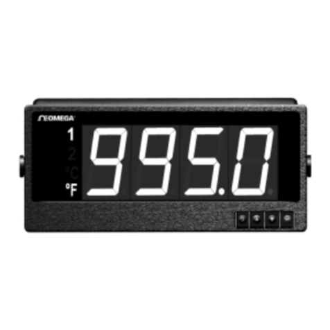
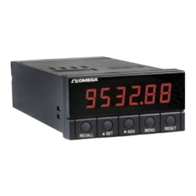
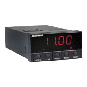
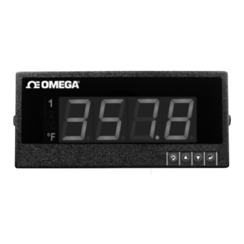
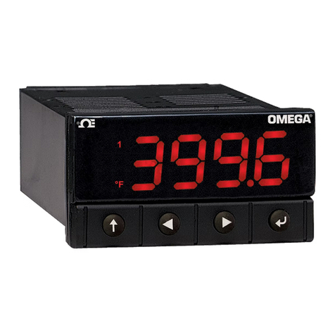
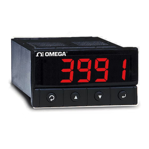
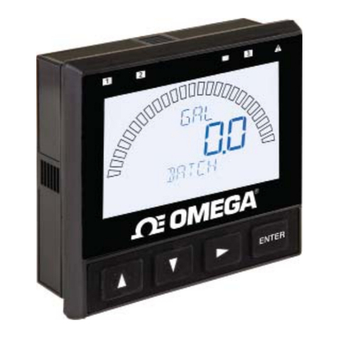
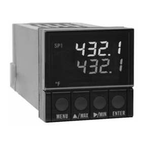
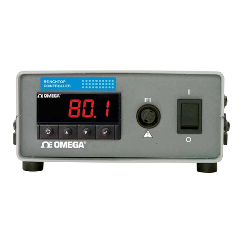
Omega i-SERIES User manual

Monitor / Controller
CCoommmmuunniiccaattiioonn MMaannuuaall
User’s Guide
www.omega.com
e-mail: [email protected]
For iSeries info:
www.omega.com/specs/iseries
For latest product manuals:
www.omegamanual.info
®
®
Shop on line at

It is the olicy of OMEGA to com ly with all worldwide safety and EMC/EMI regulations that a ly.
OMEGA is constantly ursuing certification of its roducts to the Euro ean New A roach Directives. OMEGA will add the CE mark
to every a ro riate device u on certification.
The information contained in this document is believed to be correct, but OMEGA Engineering, Inc. acce ts no liability for any
errors it contains, and reserves the right to alter s ecifications without notice.
WARNING: These roducts are not designed for use in, and should not be used for, atient-connected a lications.
!This device is marked with the international caution symbol. It is im ortant to read the Setu Guide before installing or
commissioning this device as the guide contains im ortant information relating to safety and EMC.
Servicin North America:
USA: One Omega Drive, P.O. Box 4047
ISO 9001 Certified Stamford CT 06907-0047
TEL: (203) 359-1660 FAX: (203) 359-7700
Canada: 976 Bergar
Laval (Quebec) H7L 5A1
TEL: (514) 856-6928 FAX: (514) 856-6886
For immediate technical or application assistance:
USA and Canada: Sales Service: 1-800-826-6342 / 1-800-TC-OMEGA®
Customer Service: 1-800-622-2378 / 1-800-622-BEST®
Engineering Service: 1-800-872-9436 / 1-800-USA-WHEN®
Mexico and TEL: (001)800-TC-OMEGA® FAX: (001) 203-359-7807
Latin America: En Es añol: (001) 203-359-7803
Servicin Europe:
Benelux: Postbus 8034, 1180 LA Amstelveen, The Netherlands
TEL: +31 20 3472121 FAX: +31 20 6434643
Toll Free in Benelux: 0800 0993344
Czech Republic: Frystatska 184, 733 01 Karviná
TEL: +420 59 6311899 FAX: +420 59 6311114
e-mail: info@omegasho .cz
France: 11, rue Jacques Cartier, 78280 Guyancourt
TEL: +33 1 61 37 29 00 FAX: +33 1 30 57 54 27
Toll Free in France: 0800 466 342
Germany/Austria: Daimlerstrasse 26, D-75392 Decken fronn, Germany
TEL: +49 7056 9398-0 FAX: +49 7056 9398-29
Toll Free in Germany: 0800 639 7678
United Kingdom: One Omega Drive
ISO 9002 Certified River Bend Technology Centre
Northbank, Irlam Manchester M44 5BD United Kingdom
TEL: +44 161 777 6611 FAX: +44 161 777 6622
Toll Free in England: 0800 488 488
OMEGAnet® On-Line Ser ice
www.omega.com
Internet e-mail
®
®

TABLE OF CONTENTS
Part 1: Before You Begin ....................................................................................2
Part 2: Introduction to Digital Communication.................................................3
2.1 O er iew.......................................................................................3
2.2 Definition of Terms ......................................................................3
Part 3: Hardware ...........................................................................................5
3.1 Communication Interfaces..........................................................5
3.2 Wiring RS-232 Interface .............................................................5
3.3 Wiring RS-485 Interface .............................................................6
Part 4: Communication Setup ............................................................................9
4.1 Flow Chart ....................................................................................9
4.2 Setup the i-Series De ice Through the Front Panel ...............10
4.3 Abbre iations, Range, Default Setup.......................................10
Part 5: i-Series Protocol....................................................................................13
5.1 Command Structure ..................................................................13
5.2 Command Formats ....................................................................14
5.3 Response Format ......................................................................19
5.4 Error Message............................................................................20
5.5 Alarm Status Characters...........................................................20
5.6 Examples of Transmitted Data .................................................21
5.7 Command Formats ....................................................................22
5.7.1 Input Type (Command Index 07)...................................22
5.7.1.1 Input Type for Temperature/Process ...............22
5.7.1.2 Input Type for Process/Strain Gauge ..............23
5.7.2 Reading Configuration (Command Index 08)..............23
5.7.2.1 Reading Configuration for
Temperature/Process........................................23
5.7.2.2 Reading Configuration for
Process/Strain Gauge .......................................24
5.7.3 Linearization Points (Command Index 29) ..................24
5.7.4 Color Display (Command Index 11)..............................25
5.7.5 Alarm 1 Configuration (Command Index 09)...............25
5.7.6 Alarm 1 Low (Command Index 12) ...............................26
5.7.7 Alarm 2 Configuration (Command Index 0A) ..............26
5.7.8 Output 1 Configuration (Command Index 0C).............27
5.7.9 Output 2 Configuration (Command Index 0D).............27
5.7.10 Communication Parameters (Command Index 10).....28
5.7.11 Bus Format (Command Index 1F) ................................28
5.7.12 Data Format (Command Index 20)................................29
5.7.13 Miscellaneous (Command Index 24) ............................29
5.7.14 % Low and % Hi (Command Index 27 and 28).............30
5.7.15 Reading Scale and Offset
(Command Index 14 and 3A).........................................30
5.7.16 Grouping Commands with the Same Formats............33
i

Part 6: Modbus Protocol...................................................................................34
6.1 Introduction................................................................................34
6.2 RTU Mode ...................................................................................34
6.3 De ice Address ..........................................................................35
6.4 Function Code............................................................................35
6.5 Data Field....................................................................................35
6.6 CRC Checking............................................................................36
6.7 Modbus RTU Registers .............................................................37
6.8 Command Format ......................................................................38
6.8.1 Read Multiple Register (03 or 04) .................................38
6.8.2 Write to Single Register (06) ........................................39
6.8.3 Diagnostic Command ....................................................41
6.8.4 Error Response ..............................................................41
Appendix A Reading Scale and Offset .........................................................43
Appendix B ASCII Chart.................................................................................48
ASCII Control Codes .................................................................49
Appendix C Examples of CRC Calculation ..................................................50
Example of CRC Calculation in “C” Language...............................................53
LIST OF FIGURES:
Figure 2.1 Transmission of “c” ....................................................................4
Figure 3.1 DB9 and RS-232 Wiring ..............................................................6
Figure 3.2 DB25 and RS-232 Wiring.............................................................6
Figure 3.3 Multipoint, Half-Duplex RS-485 Wiring .....................................7
Figure 4.1 Flow Chart for Communication Option......................................9
LIST OF TABLES:
Table 3.1 Communication Interface ...........................................................5
Table 3.2 Wiring RS-232 Interface ..............................................................6
Table 3.3 RS-485 Half Duplex Hook-up......................................................8
Table 4.1 Abbre iations, Range, Default Setup ......................................10
Table 5.1 Command Prefix Letters...........................................................13
Table 5.2 Command Formats....................................................................14
Table 5.3 Command Letters and Suffix ...................................................14
Table 5.4 Command Letters and Suffix ...................................................16
Table 5.5 Echo Mode .................................................................................19
Table 5.6 No Echo Mode ...........................................................................19
Table 5.7 Error Message ...........................................................................20
Table 5.8 Alarm Status Characters ..........................................................20
Table 5.9 Con ersion Number ..................................................................30
Table 5.10 Commands with Numeric Data Format ...................................33
Table 6.1 Function Code ...........................................................................35
Table 6.2 Modbus Registers .....................................................................37
Table A.1 Con ersion Number ..................................................................43
Table A.2 Input Resolution Multiplier .......................................................43
ii

NOTES, WARNINGS and CAUTIONS
Information that is es ecially im ortant to note is identified by following labels:
• NOTE
• WARNING or CAUTION
• IMPORTANT
• TIP
NOTE: Provides you with information that is im ortant to successfully
setu and use the Programmable Digital Meter.
CAUTION or WARNING: Tells you about the risk of electrical shock.
CAUTION, WARNING or IMPORTANT: Tells you of circumstances or
ractices that can effect the instrument’s functionality and must refer
to accom anying documents.
TIP: Provides you hel ful hints.
1

PART 1
BEFORE YOU BEGIN
Customer Ser ice
If you need assistance, lease call the nearest Customer Service De artment, listed in
this manual.
Manuals, Software
The latest O eration and Communication Manual as well as free configuration software
and ActiveX controls are available from the website listed in this manual or on the
CD-ROM enclosed with your shipment.
Communication Menu
The Communication menu only a ears with devices urchased with the RS-232C /
RS-485 Serial Communications O tion. Purchasing the controller with Serial
Communications ermits a controller to be connected directly to the PC’s available COM
ort. Device can be configured or monitored from an IBM PC com atible com uter using
software available on our CD or on our website.
To Disable Outputs
Standby Mode is useful during setu of the controller or when maintenance of the
system is necessary. When the controller is in standby, it remains in the ready condition
but all out uts are disabled. This allows the system to remain owered and ready to go.
1. When the controller is in “RUN” Mode, push dtwice to disable all out uts and
alarms. It is now in “STANDBY” Mode.
2. Push donce more to resume “RUN” Mode.
PUSH dTWICE to disable the system during an EMERGENCY.
To Reset the Meter
1. When the controller is in the “MENU” Mode, push cdown button once to direct
controller one ste backward of the to menu item.
2. Push ctwice to reset controller, rior to resuming “Run” Mode exce t after
“Set oints” and “Alarms” that will go to the “Run” Mode without resetting the
controller.
2

PART 2
INTRODUCTION TO DIGITAL COMMUNICATION
2.1 O er iew
This manual describes how to use a digital communication link and i-SERIES or
MODBUS communication rotocols to o erate the i-Series controllers. It has been
assumed that the user has some ex erience of communication rotocols and some
familiarity with i-Series controllers.
2.2 Definitions of terms
This guide is intended to hel the user to become familiar with digital communication
between a com uter (or other controlling instrument) and one or more devices.
User of this manual should be familiar with following definitions:
• Serial Communication is the exchange of the data one bit at a time on a single data
line. Serial com ares with arallel communication, which sends several bits of
information simultaneously over multi le lines or channels.
• Interface are connections over which com uters communicate. They may use one air
of wires to send information in one direction and another air to send in the o osite
direction (full duplex). They may also use one air to send the information in both
directions (half duplex).
• Bit is a unit of digital data (binary digit) either a “1” or “0”.
• Byte is a string of seven or eight bits, which re resents a single character.
• ASCII (American Standard Code for Information Interchange) – is a 7-bit code defines
128 characters, which include digits, u er and lowercase letters, unctuation symbols,
and control codes such as backs ace, line feed, carriage return and so on. The ASCII
code can be written in a base – 16 number system, called hexadecimal (“hex”). The first
10 digits of this system are re resented by the numbers 0 through 9, and the other six
digits are re resented by the letters A through F. The 128 ASCII character code with the
decimal, hexadecimal and binary equivalents is listed in A endix B.
• Synchronous and Asynchronous Communications
There are two basic ty es of serial communications, synchronous and asynchronous.
With synchronous communications, the two devices initially synchronize themselves to
each other, and then continually send characters to stay in sync. Asynchronous means
“no synchronization”, and thus does not require sending and receiving idle characters.
However, the beginning and end of each byte of data must be identified by start and sto
bits. The serial orts on IBM-style PCs are asynchronous devices and therefore only
su ort asynchronous serial communications.
• Start and Stop Bits
The start and sto bits identify the beginning and end of each character and ermit a
receiver to resynchronize a local clock to each new character. The start bit indicates
when the data byte is about to begin and the sto bit signals when it ends. The start bit is
always a 0. The sto bit is always a 1.
3

• Parity Bit
Besides the synchronization rovided by the use of start and sto bits, an additional bit
called a arity bit may o tionally be transmitted along with the data. A arity bit affords a
small amount of error checking, to hel detect data corru tion that might occur during
transmission. You can choose either e en arity, odd arity or no arity at all. When
even or odd arity is being used, the number of marks (logical 1 bits) in each data byte
are counted, and a single bit is transmitted following the data bits to indicate whether the
number of 1 bits just sent is even or odd.
For exam le, when even arity is chosen, the arity bit is transmitted with a value of 0 if
the number of receding marks (1’s) is an even number. For the binary value of 0110 0011
the even arity bit would be 0. If even arity were in effect when the binary number
1101 0110 is sent, then the arity bit would be 1. Odd arity is just the o osite, and the
arity bit is 0 when the number of mark bits (1’s) in the receding word is an odd number.
Parity error checking is very rudimentary. While it will tell you if there is a single bit error
in the character, it doesn't show which bit was received in error. Also, if an even number
of bits are in error then the arity bit would not reflect any error at all. No arity ignores
the arity bit. When transmitted, each character is receded by a start bit and followed
by a sto bit lus an o tional arity bit, making train of 10 or 11 bits for each transmitted
character. The Figure 2.1 below shows transmission of the 7 bits of the ASCII lower case
“c” with start, sto and even arity bits.
• Baud Rate
The baud rate refers to the data transmission. It s ecifies the communication rate over
the bus. When a change in signal re resents one data bit, baud rate is equal to bits er
second (b s). Standard baud rates for com uters are 300, 600, 1200,2400, 4800, 9600
and 19200 baud.
Figure 2.1 Transmission of “c” with start, stop, and e en parity bits.
• Communication Protocol
A data communication rotocol defines the rules and structure of messages used by all
devices on a network for data exchange. This rotocol also defines the orderly exchange
of messages, and the detection of errors. i-Series controllers use i-SERIES and
MODBUS communication rotocols.
7 - BIT CHARACTER
12345678
1
0
START BIT EVEN PARITY BIT
STOP BIT
4

PART 3
HARDWARE
3.1 Communication Interfaces
Two communication interfaces are su orted in the i-Series devices: RS-232 and
RS-485. These standards define the electrical characteristics of a communication
network.
• The RS-232 standard (point-to-point) allows a single device to be connected to a PC.
The i-Series devices o erate with full-du lex RS-232 using three wires: a Rx - receive
wire, a Tx - transmit wire and a common ground wire. RS-232 cable length is limited to
50 feet.
• The RS-485 standard (multipoint) allows one or more devices to be connected
(multi-dro ed) using a two wire connection (half-du lex) +Rx / +Tx and -Rx / -Tx.
Use of RS-485 communications allows u to 32 “remote” devices to connect to the
“master” com uter with cable length u to 4000 feet long.
• Both interfaces use standard RS-232/RS-485 voltage levels.
Although the RS-485 is commonly referred to as a “two wire” connection, the
i-Series also rovides a ground / return shield connection to use as a common
connection for EMI noise rotection.
The Table 3.1 shows the differences between RS-232 and RS-485 communication
interfaces.
Table 3.1 Communication Interfaces
Data Transmission Characteristics RS232 RS485
Transmission Mode Single ended Differential
Electrical connections 3 wire 2 wire
Drivers er line 1 driver 32 drivers
Receivers er line 1 receiver 32 receiver
Maximum data rate 20k bits/s 10M bits/s
Maximum cable length 50 ft (15 meters) 4000 ft (1200 meters)
Changing between RS-232 and RS-485 is ossible through front anel buttons
(see Part 4 for details).
3.2 Wiring RS-232 Interface
Most PC’s rovide an RS-232 ort for digital communication. The RS-232 communication
uses three wire full-du lex system: a line for receiving data, a line for transmitting data
and a common line between the com uter and device. Usually PCs use a 25 or 9 in
connector.
Caution: Do not connect ower to your instrument until you have com leted all
serial interface connections. Failure to do so may result in injury.
5

Figures 3.1 and 3.2 show the three-wire RS-232 connections between the host com uter
using a 9- in or 25- in “D” connector and the i–Series device.
Figure 3.1 Wiring between DB9 computer connector and RS-232 controller interface
Figure 3.2 Wiring between DB25 computer connector
and RS-232 controller interface
Table 3.2 shows the in connection assignments between the RS-232 connector on the
meter and the 9- in or 25- in “D” connectors of your com uter.
Table 3.2 Wiring RS-232 Interface
COMPUTER i-SERIES
FUNCTION/
PIN FUNCTION DB9 DB25 LABEL
Receive (Rx) 2 3 Transmit (Tx)
Transmit (Tx) 3 2 Receive (Rx)
Common ground 5 7 RTN
3.3 Wiring RS-485 Interface
RS-485 interface uses a two wire communication system (one for transmitting and one
for receiving) lus a common wire to connect to the shield of a cable. It is recommended
to use a shielded cable with one twisted air.
Use of twisted air and shield will significantly im rove noise immunity.
i-SERIES
12 3 4 5
DB-25 CONNECTOR
67 8 9 10 11 12 13
14 15 16 17 18 17 20 21 21 23 24 25
i-SERIES
12345
6789
DB-9 CONNECTOR
6

Figure 3.3 shows multi oint, half-du lex RS-485 interface connections for i-Series.
Figure 3.3 Multipoint, Half-Duplex RS-485 wiring
Value of the termination resistor is not critical and de ends on the cable
im edance.
7

Table 3.3 shows RS-485 half-du lex hooku using a com uter’s RS-232 interface, an
RS-485 interface converter, and an i-Series controller.
Table 3.3 RS-485 Half-Duplex Hook-up
COMPUTER CONVERTER BOX i-SERIES
FUNCTION/
PIN FUNCTION DB9 DB25 COMPUTER i-Series LABEL
SIDE SIDE
Rx/Tx 2 3 SEE CONVERTER’S -Rx/-Tx Tx
Rx/Tx 3 2 MANUFACTURING +Rx/+Tx Rx
Common ground 5 7 SPECIFICATION COM RTN
Communication Interfaces shown above are those which used on i-Series
devices. Other ty es of Communication Interfaces are not covered in this
cha ter.
8

PART 4
COMMUNICATION SETUP
4.1 Flow Chart
Figure 4.1 Flow Chart for Communication Option
9

4.2 Setup the i-Series De ice Through the Front Panel
You can setu your device by ressing the ush buttons on the front anel.
ENTER COMMUNICATION OPTION MENU:
Press a1) Press auntil CNFG rom t a ears.
Press d2) Dis lay advances to INPT In ut Menu.
Press a3) Press a, until dis lay advances to COMM Communication O tions Menu.
Press d4) Dis lay advances to C.PAR Communication Parameters Submenu.
a- Use ato advance/navigate through all Communication Menu items.
b- Press dto access the submenus from a to level of Communication Menu item.
Press dto store a submenu selection.
c- Press bto scroll through “flashing” selection. When a numerical value is dis layed,
ress bto change a value of this arameter.
d- Press cto go back to a to level of Communication Menu item. Press ctwice to
reset the device to Run mode.
4.3 Abbre iations, Range, Default Setup
The Communication Menu Dis lay items use some abbreviations and com act wording
shown on Table 4.1.
Table 4.1 Abbre iations, Range, Default Setup
Display Function Range/ Definition Factory
(abbre iations) Default
C.PAR Communication
Parameter:
bAUd Baud rate 300, 600,1200, 2400
4800, 9600, 19200 9600
PRtY (odd_, EVEN, Parity Odd, Even, No odd
_No_)
dAtA (7.bit, 8.bit) Data bit 7 bit, 8 bit 7.bit
StOP (1.bit, 2.bit) Sto bit 1 bit, 2 bit 1.bit
bus.F Bus format:
M.bUS Modbus rotocol Yes – Modbus rotocol enabled
No – i-Series rotocol enabled _No_
_LF_ Line feed Yes – rint on every other line
No – rint on every line _No_
ECHO Echo Yes – echo the command _YES
arameter
No – no echo
StNd (232C, 485_) Communication RS-232, RS-485 232C
Standard
ModE (CMd_, CoNt) Data Flow Mode Command – o erate in Command CMd_
Mode (res ond to valid command).
Continuous – o erate in
Continuous mode (transmit
different measurement values
continuously on the bus).
10

Abbre iations, Range, Default Setup Continued
SEPR (SPCE, _cR_) Data Se aration S ace – s ace inserted after each SPCE
Character iece of data.
Carriage Return – carriage return
inserted after each iece of data
dAt.F Data Format:
stAt Alarm Status Yes – enables the transmission of _No_
Alarms Value
No – disable
RdNG Reading Yes – enables the transmission _Yes
of Reading Value
No – disable
PEAk Peak Yes – enables the transmission _No_
of Peak Value
No – disable
VALY * Valley Yes – enables the transmission _No_
of Valley Value
No – disable
GROS ** Gross Yes – enables the transmission _No_
of Gross Value
No – disable
UNit Units Yes – enables the transmission _No_
of Units of Measurement
No – disable
AddR Multi oint Address 0000 to 0199 – Addressed Meter 0001
tR.tM Transmit Time 0000 to 5999 sec – transmission 0016
Interval Time Interval between consecutive
transmissions in Continuous Mode.
Recognition 20 Hex to 7F Hex (32 to 127 Dec) *
Character –see Table 2.1, exce t “^”, “A”,
“E”
* - For Tem erature/Process instrument only
** - For Process/Strain Gauge instrument only
1. There is no Continuous Mode, when device is configured to use the RS-485
interface standard.
2. The Multipoint Address will be included in the transmission data if RS-485
standard has been selected in menu items.
3. Transmit time is available only when device has configured for Continuous
Mode and RS-232 Standard.
4. If the meter is in oint-to- oint Continuous Mode, it ignores any transmitted
commands exce t Crtl S, which will sto transmission.
11

Communications Parameters Submenu
Allows the user to adjust Serial Communications settings of the device. When
connecting an instrument to a com uter or other device, the Communication Parameters
must match. Generally the default settings shown in Table 4.1 should be utilized.
Bus Format Submenu
Determines communications standards and command/data formats for transferring
information into and out of the device via the Serial Communications Bus.
Bus Format submenus essentially determine how and when data can be accessed via
the Serial Communications of the device.
Data Format Submenu
Preformatted data can be sent automatically or u on request from the device. Use the
Data Format Submenus to determine what data will be sent in this reformatted data
string. At least one of the Data Format subo tions must be enabled to send out ut data
to the Serial Bus.
Recognition Character
A selectable symbol transmitted as the first character of each message from the
com uter, which is used for message security: the meter ignores messages without this
symbol.
12

PART 5
i-SERIES PROTOCOL
To Enable the i-Series Protocol, set Modbus menu item to “No” in the Bus
Format Submenu of the Communication Menu. Refer to Section 5.7.11.
A Data Communication Protocol defines the rules and structure of messages used by all
devices on a network for data exchange. A ty ical transaction will consist of a request to
send from the “master” followed by the res onse from the “slave”.
5.1 Command Structure
The device can be commanded to “Read”, i.e., to transmit (send) data from either the
nonvolatile memory (EEPROM) or from the volatile working memory (RAM).
The device can also be commanded to “Write”, i.e., store new values for data rocessing
or control.
There are different command ty es associated in communicating with your meter shown
in Table 5.1, which shows the Command Prefix Letters (Command Classes).
Table 5.1 Command Prefix Letters
COMMAND PREFIX
(COMMAND CLASS) MEANING
^AE S ecial read, Communication arameters
P (Put) Write HEX data into RAM
W (Write) Write HEX data into EEPROM. 1,000,000 writes to EEPROM
is guaranteed!
G (Get) Read HEX data from RAM
R (Read) Read HEX data from EEPROM
URead status byte
VRead measurement data string in Decimal format
XRead measurement data values in Decimal format
DDisable
EEnable
ZReset
13

5.2 Command Formats
Table 5.2 shows the command formats for i-Series devices.
Table 5.2 Command Formats
For “P” and “W” Command For “G” and “R” Command For “X”, “V”, “U”, “D”,
classes: classes: “E”, and”Z” Command
classes:
Point-to-point mode Point-to-point mode Point-to-point mode
* ccc<data><cr> * ccc <cr> * ccc <cr>
Multipoint mode Multipoint mode Multipoint mode
* nnccc [<data>]<cr> * nnccc <cr> * nnccc <cr>
Where:
“*” is the selected Recognition Character. You may select any ASCII table symbol from
“!” (HEX address “21”) to the right-hand brace (HEX “7D”) exce t for the caret “^”, “A”,
“E”, which are reserved for bus format request.
“ccc” stands for the hex-ASCII Command Class letter (one of eleven given in Table 5.1),
followed by the two hex-ASCII Command Suffix characters identifying the meter data,
features or menu items to which the command is directed (given in Table 5.3).
“<data>” is the string of characters containing the variable information the com uter is
sending to the meter. These data (whether BCD or binary) are encoded into hex-ASCII
characters, two characters to the byte. Square brackets (indicating o tional status)
enclose this string, since some commands contain no data.
“<nn>” are the two ASCII characters for the device Bus Address of RS-485
communication . Use values from “00” to hex “C7” (199 decimal).
Table 5.3 and 5.4 shows the command letters and suffix for i-Series devices.
Table 5.3 Command Letters and Suffix for Temperature/Process and Process/Strain Gauge
Instrument
Command Command Function Command # Of Default
Index Bytes Characters Value
RW 01 SP1 3 6 200000
RW 02 SP2 3 6 200000
GPRW 03 RDGOFF 3 6 200000
RW 04 ANLOFF 3 6 400000
RW 05 ID 2 4 0000
-06 N/A - --
RW 07 INPUT 1 2 04
GPRW 08 RDGCNF 1 2 4A
RW 09 AL1CNFG 1 2 00
RW 0A AL2CNFG 1 2 00
RW 0B LOOP BREAK TIME 2 4 003B
RW 0C OUT1CNF 1 2 00
RW 0D OUT2CNF 1 2 60
RW 0E RAMPTIME 2 4 0000
14

Command Letters and Suffixes Continued
Command Command Function Command # Of Default
Index Bytes Characters Value
RW 0F ANLSCL 3 6 9186A0
RW 10 COMM.PARAMETERS 1 2 0D
RW 11 COLOR 1 2 09
RW 12 AL1LO 3 6 A003E8
RW 13 AL1HI 3 6 200FA0
GPRW 14 RDGSCL 3 6 100001
RW 15 AL2LO 3 6 A003E8
RW 16 AL2HI 3 6 200FA0
GPRW 17 PB1/DEAD BAND 2 4 00C8
GPRW 18 RESET 1 2 4 00B4
GPRW 19 RATE 1 2 4 0000
GPRW 1A CYCLE 1 1 2 07
-1B N/A - - -
GPRW 1C PB2/DEAD BAND 2 4 00C8
GPRW 1D CYCLE 2 1 2 07
RW 1E SOAK TIME 2 4 0000
RW 1F BUS FORMAT 1 2 14
GPRW 20 DATA FORMAT 1 2 02
RW 21 ADDRESS 1 2 01
RW 22 Transit Time Interval 2 4 0010
-23 N/A - --
RW 24 Miscellaneous 1 2 00
RW 25 C.J. OFFSET ADJ. 3 6 200000
RW 26 Recognition Character 1 2 2A
RW 27 %LOW 1 2 00
RW 28 %HI 1 2 63
D 01 DISABLE ALARM 1 0 0 -
D 02 DISABLE ALARM 2 0 0 -
D 03 STANDBY 0 0 -
D 04 DISABLE SELF 0 0 -
E 01 ENABLE ALARM 1 0 0 -
E 02 ENABLE ALARM 2 0 0 -
E 03 DISABLE STANDBY 0 0 -
E 04 ENABLE SELF 0 0 -
X 01 SEND READING 0 0 -
X 02 SEND PEAK READING 0 0 -
X 03 SEND VALLEY READING 0 0 -
U 01 SEND ALARM STATUS 0 0 -
U 03 SEND SW VERSION 0 0 -
V 01 SEND DATA STRING 0 0 -
Z 02 HARD RESET 0 0 -
15

Table 5.4 Command Letters and Suffix for Process/Strain Gauge Instrument with
10 Linearization Points
Command Command Function Command # Of Default
Index Bytes Characters Value
RW 01 SP1 3 6 200000
RW 02 SP2 3 6 200000
GPRW 03 RDGOFF 3 6 200000
RW 04 ANLOFF 3 6 400000
RW 05 ID 2 4 0000
-06 N/A - --
RW 07 INPUT 1 2 04
GPRW 08 RDGCNF 1 2 4A
RW 09 AL1CNFG 1 2 00
RW 0A AL2CNFG 1 2 00
RW 0B LOOP BREAK TIME 2 4 003B
RW 0C OUT1CNF 1 2 00
RW 0D OUT2CNF 1 2 60
RW 0E RAMPTIME 2 4 0000
RW 0F ANLSCL 3 6 9186A0
RW 10 COMM.PARAMETERS 1 2 0D
RW 11 COLOR 1 2 09
RW 12 AL1LO 3 6 A003E8
RW 13 AL1HI 3 6 200FA0
GPRW 14 RDGSCL 3 6 100001
RW 15 AL2LO 3 6 A003E8
RW 16 AL2HI 3 6 200FA0
GPRW 17 PB1/DEAD BAND 2 4 00C8
GPRW 18 RESET 1 2 4 00B4
GPRW 19 RATE 1 2 4 0000
GPRW 1A CYCLE 1 1 2 07
-1B N/A - - -
GPRW 1C PB2/DEAD BAND 2 4 00C8
GPRW 1D CYCLE 2 1 2 07
RW 1E SOAK TIME 2 4 0000
RW 1F BUS FORMAT 1 2 14
GPRW 20 DATA FORMAT 1 2 02
RW 21 ADDRESS 1 2 01
RW 22 Transit Time Interval 2 4 0010
-23 N/A - --
RW 24 Miscellaneous 1 2 00
RW 25 C.J. OFFSET ADJ. 3 6 200000
RW 26 Recognition Character 1 2 2A
RW 27 %LOW 1 2 00
RW 28 %HI 1 2 63
16
Other manuals for i-SERIES
1
Table of contents
Other Omega Controllers manuals

Omega
Omega MICROMEGA CN77000 series User manual

Omega
Omega CSi32 User manual

Omega
Omega CNI16 User manual

Omega
Omega PHCN-37 Troubleshooting guide

Omega
Omega PHCN-37 User manual

Omega
Omega DPU91-BC SERIES User manual

Omega
Omega CN16Pt User manual

Omega
Omega i Series User manual

Omega
Omega CN4420 Series User manual

Omega
Omega CN8EPt User manual

Omega
Omega CN38S User manual

Omega
Omega CNI16D User manual

Omega
Omega LINKR-M1 User manual

Omega
Omega DPF700 User manual

Omega
Omega ILD24-UTP User manual

Omega
Omega CNiS16D User manual

Omega
Omega CND3 Series User manual

Omega
Omega i Series User manual

Omega
Omega CN32Pt User manual

Omega
Omega i Series User manual