Stairmaster StairMaster Zephyr Quick start guide
A
ASSEMBLY
SSEMBLY I
INSTRUCTIONS
NSTRUCTIONS / O
/ OWNERS
WNERS M
MANUAL
ANUAL
Part No. 060-0036 Revision: B Date: 09/10
IMPORTANT:
:
:
READ ALL ASSEMBLY INSTRUCTIONS AND SAFETY PRECAUTIONS BEFORE USING THIS PRODUCT. REFERENCE ALL
SAFETY GUIDELINES AND WARNING LABELS. RETAIN PRODUCT LITERATURE FOR FUTURE REFERENCE.
SAFETY :PROPERLY WARM UP AND STRETCH BEFORE EXERCISING. IF YOU FEELPAIN ORDIZZINESS AT ANY TIME WHILE
EXERCISING , STOP IMMEDIATELY AND CONSULT YOUR PHYSICIAN.
StairMaster Zephyr
®

PAGE 1 ASSEMBLY INTRO
A
ASSEMBLY
SSEMBLY P
PREPARATION
REPARATION
To ensure ease of product assembly, please take time to verify the size and quantities of all required
assembly hardware. Use the itemized parts listing and hardware chart for reference.
The product assembly process has been documented in easy to follow stages. Please read all assembly
instructions carefully. Take time to review the manual and familiarize yourself with the entire
assembly process before proceeding.
Assembly Tip: It is always helpful to pre-stage the items needed for each assembly step.
Perform product assembly in a 4ft. x 6ft. flat area. Note: After assembly is completed, allow a minimal
of 2-3ft. of space on each side of bike for user access and dismounting.
Do not dispose of any packaging materials until assembly of the product is completed.
Assembly tools are included, but you may also use standard household tools to complete assembly of
this product.
If you experience problems with operation of the equipment after assembly, please reference the
troubleshooting guide in this manual.
For added component life, follow the preventative maintenance tips listed in this manual.
Make sure to completely fill-out the product registration form & return it to us within 30-days of
purchase.
Please contact us if you have additional questions or need service assistance at 1-888-678-2476.
I
IMPORTANT
MPORTANT P
PRECAUTIONS
RECAUTIONS
WARNING: To reduce the risk of injury, please read the following precautions before assembling or using your new product.
1. It is the responsibility of the owner to ensure that all users of this equipment are adequately informed of stated precautions.
2. Read all instructions and enclosed literature carefully. Understand the assembly and operation before using the equipment.
3. Use equipment on a flat level surface. Use adjustment levelers on the bottom of equipment to help stabilize unit.
4. It’s recommended to place an exercise mat beneath the equipment for added protection of floors or carpets.
5. Keep children & pets away from equipment at all times. Lock the fan wheel in place for added safety while not in use.
6. Inspect product on a frequent basis. Tighten loose assemblies or hardware as needed. Replace worn or damaged parts.
7. This equipment is intended for internal home use only. Do not use in a non-residential environment. Use in non-recommended
environments can lead to serious injury and will void all related warranties & liabilities.
8. Recommended user weight should not exceed 300 lbs.
9. Keep equipment clean and properly maintained.
10. Observe and adhere to all warning labels posted on equipment.
11. Properly warm-up and stretch before starting any strength training or cardio exercise routine.
12. If you feel pain or dizziness at any time while exercising, stop immediately and consult your physician.
Safety Warning: Before starting an exercise program, consult your physician. This is especially important for individuals over the age
of 35 or persons with pre-existing health problems. It’s important to read all instructions carefully. We assume no responsibility
for personal injury or consequential damages sustained by or through the use of this equipment. Additional terms & con-
ditions are listed in the back of this manual or enclosed owners manual.
Colors and specifications are subject to change without notice.

ASSEMBLY PARTS LISTING PAGE 2
A
ASSEMBLY
SSEMBLY P
PARTS
ARTS L
LIST
IST
Item # Part Number Description QTY.
1 060-0038
Base Frame Assembly 1
2 060-0001 Front Stabilizer Assembly 1
3 060-0002 Rear Stabilizer Assembly 1
4 060-0003
Sensor Cable 1
5060-0004 Console 1
6 060-0005 Console Mast 1
7 060-0006
Adjustable Seat Slider 1
8 060-0007
Seat Post 1
91
Seat
060-0008
10 060-0009 Seat Slider Adjustment Knob 1
11 060-0010 Seat Back Post 1
12 060-0011 Seat Post Adjustment Knob 1
13 060-0012
Seat Back Bracket 1
14 060-0013 Seat Back Pad 1
15 060-0014 Connecting Arm (Preinstalled) 2
16 060-0015 Left Pivot Arm Assembly 1
17 060-0016 Right Pivot Arm Assembly 1
18 060-0017 Left Foot Rest 1
19 060-0018 Right Foot Rest 1
20 060-0019 Left Pedal 1
21 060-0020 Right Pedal 1
22 060-0021 (Large) Carriage Bolt M8 x 50 Length 4
23 060-0022 (Large) Spring Washer 20 x 8.5 x 1.5t 12
24 060-0023 (Large) Acorn Nuts M8 12
25 060-0024 (Small) Carriage Bolts M6 x 35 Length 2
26 060-0025 Pan Head Screw 4
27 060-0026 Button Head Allen Bolt M8 x 40 Length 2
28 060-0027 Button Head Allen Bolt M8 x 12 Length 2
29 060-0028 Button Head Allen Bolt M8 x 15 Length 6
30 060-0029 Pivot Bolt M8 x 35 Length 2
31 060-0030 Flat Washer 20 x 8.5 x 1.5t 2
32 060-0031 Nylon Nut M8 2
33 060-0032 (Small) Spring Washer 10 x 6.5 x 1.5t 2
34 060-0033 (Small) Acorn Nut M6 2
35 060-0034 Cage, Water Bottle 1
36 060-0035 Water Bottle 1

PAGE 3
10
12
3
6
7
8
12
15
19
21
1
28
17
2
EXPLODED VIEW
5
4
27
24
23
22
33
34
18
20
25
16
22
23
24
29 23
24
30
31
23
24
NOTE
NOTE: THE EXPLODED PARTS VIEW IS SHOWN FOR REFERENCE ONLY. SOME ITEMS MAY BE PREASSEMBLED.
: THE EXPLODED PARTS VIEW IS SHOWN FOR REFERENCE ONLY. SOME ITEMS MAY BE PREASSEMBLED.
PLEASE REFER TO THE INDIVIDUAL ASSEMBLY STAGE INSTRUCTIONS FOR DETAILED PARTS ORIENTATION.
PLEASE REFER TO THE INDIVIDUAL ASSEMBLY STAGE INSTRUCTIONS FOR DETAILED PARTS ORIENTATION.
13
14
9
11
26
26
36 35
StairMaster® Zephyr Assembly Parts
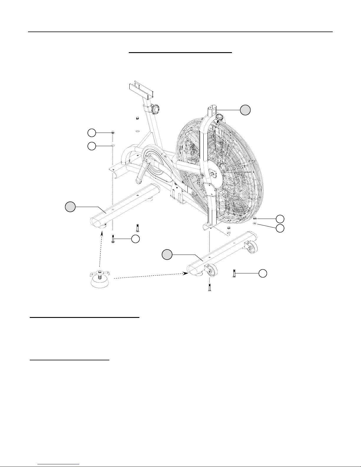
ASSEMBLY STAGE #1
Attach Stabilizers to the Main Base
Assembly Hardware Required:
#22 Carriage Bolt Qty. 4 #24 Acorn Nut Qty. 4
#23 Spring Washer Qty. 4
Assembly Description:
A) Assemble the Front Stabilizer Assembly (#2) to the Main Base Assembly (#1) using 2-Carriage Bolts (#22),
2-Flat Washers (#23), and 2-Acorn Nuts (#24). Note: Make sure that the transport wheels on the Front Stabilizer
are facing away from the Main Base Assembly as shown.
B) Assemble the Rear Stabilizer Assembly (#3) to the Main Base Assembly (#1) using 2–Carriage Bolts (#22), 2
–Flat Washers (#23), and 2–Acorn Nuts (#24).
C) Use the Adjustable Levelers on the bottom of the Stabilizer Assemblies to adjust the bike and keep it from rocking
on an uneven surface (Figure 1).
Assembly Step #1 completed.
ASSEMBLY INSTRUCTION PAGE 4
24
23
22
3
24
23
22
2
1
Adjustable Levelers
Figure 1

ASSEMBLY STAGE #2
Attach Console Mast & Mount Computer on the Main Base
Assembly Hardware Required:
#25 Carriage Bolt Qty. 2 #33 Spring Washer Qty. 2
#26 Pan Head Screw Qty. 2 #34 Acorn Nut M6 Qty. 2
Assembly Description:
A) Carefully route the Sensor Cable (#4) through the Computer Mast (#6) and slide the mast down onto the
corresponding mounting area of the Base Frame Assembly. Secure the mast to the base frame using 2-Carrriage
Bolts (#25), 2-Spring Washers (#33), and 2-Acorn Nuts (#34).
B) Install (2) AA Batteries into the back of the Computer (#5), as shown in Figure 2. Connect the Sensor Cable (#4)
to the receptacle end of the cable coming from the back ofthe computer. Tuck the excess cable length into the mast
and slide the computer onto the mast mounting plate. Secure the computer in place using 2-Pan Head Screws (#26).
Assembly Stage #2 completed.
ASSEMBLY INSTRUCTIONPAGE 5
34
25
33
4
6
5
Figure 2
#4 Sensor Wire
Computer Back View
26

ASSEMBLY STAGE #3
Attach Seat Slider and Seat to Main Base Assembly
Assembly Hardware Required:
#27 Button Head Allen Bolt Qty. 2 #28 Button Head Allen Bolt Qty. 2
Assembly Description:
A) Insert the Adjustable Seat Slider (#7) into the u-channel of the Seat Support Post (#8). Secure the seat slider
assembly in place using the 1-Seat Adjustment Knob (#10).
B) Attach the Seat Back Post (#11) to the Adjustable Seat Slider (#7) using 2-Button Head Allen Bolts (#27).
C) Assemble Seat (#9) onto the knurled post of the seat slider. Set the seat at the desired position and secure it in place
by tightening the u-clamp on the underside. Tighten the clamp until the seat no longer twists or tilts.
D) Assemble the Seat Back Bracket (#13) to the Back Pad (#14) using 2-Button Head Allen Bolts (#28). Slide the
back pad assembly over the Seat Back Post (#11) and lock into a desired position using Back Pad Adjustment Knob
(#12)
Seat Adjustments: Adjust the seat height by unscrewing and pulling out on the Seat Post Adjustment Knob (#12).Select a
desired seat post height and retighten the knob until seat post is secure. Proper Height Adjustment: Adjust seat height so the user
is comfortable during use (pedaling motion). As a reference point, the users leg should be slightly bent at the bottom of the pedal
stroke. The horizontal seat position can be adjusted using the Seat Slider (#7) . Note: If the seat post wobbles during use, make sure
the u-clamp and all adjustment knobs are securely tightened.
Assembly Stage #3 completed.
ASSEMBLY INSTRUCTION PAGE 6
7
10
8
27
12
9
14
13
12
28
11
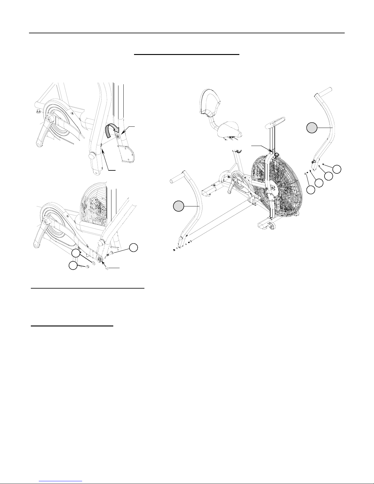
ASSEMBLY STAGE #4
Attach Pivot Arms to the Main Base
Assembly Hardware Required:
#23 Spring Washer Qty. 2 #30 Pivot Bolt M8 Qty. 2
#24 Acorn Nut M8 Qty. 2 #31 Flat Washer Qty. 2
Assembly Description:
A) Install the Pivot Arms (#16 & #17) by threading the (preinstalled) pivot shaft into the corresponding pivot-boss of
the Base Frame Assembly (#1). Using a standard crescent wrench (not included), thread each shaft into the pivot
-boss using a clockwise rotation. Fully tighten each shaft until it is flush against the pivot-boss of the Base Frame
Assembly. (Reference Figure #3)
B) Once the Pivot Arms are mounted to the Base Frame Assembly, attach the ends of the Connecting Arms (#15)
using 1-Pivot Bolt (#30), 1-Flat Washer (#31), 1-Spring Washer (#23), and 1-Acorn Nut (#24) per side.
(Figure #4).
Hardware Orientation:The #31-Flat Washer must be placed in-between the connecting arm and inner flange mount-
ing of the Pivot Arm. (Reference Figure #4).
Safety Note: The arm / pedal movement can be locked in place by turning the Fan Safety Knob until it makes contact
with the fan wheel..
Assembly Stage #4 completed.
ASSEMBLY INSTRUCTIONPAGE 7
Figure 3
Figure 4
Place #31 Flat Washer in-between the Connecting Arm and the Pivot Arm
30
24
23
17
16
Pivot Shaft
Pivot-Boss
30
31
23
24
Fan Safety Knob
ASSEMBLY INSTRUCTION
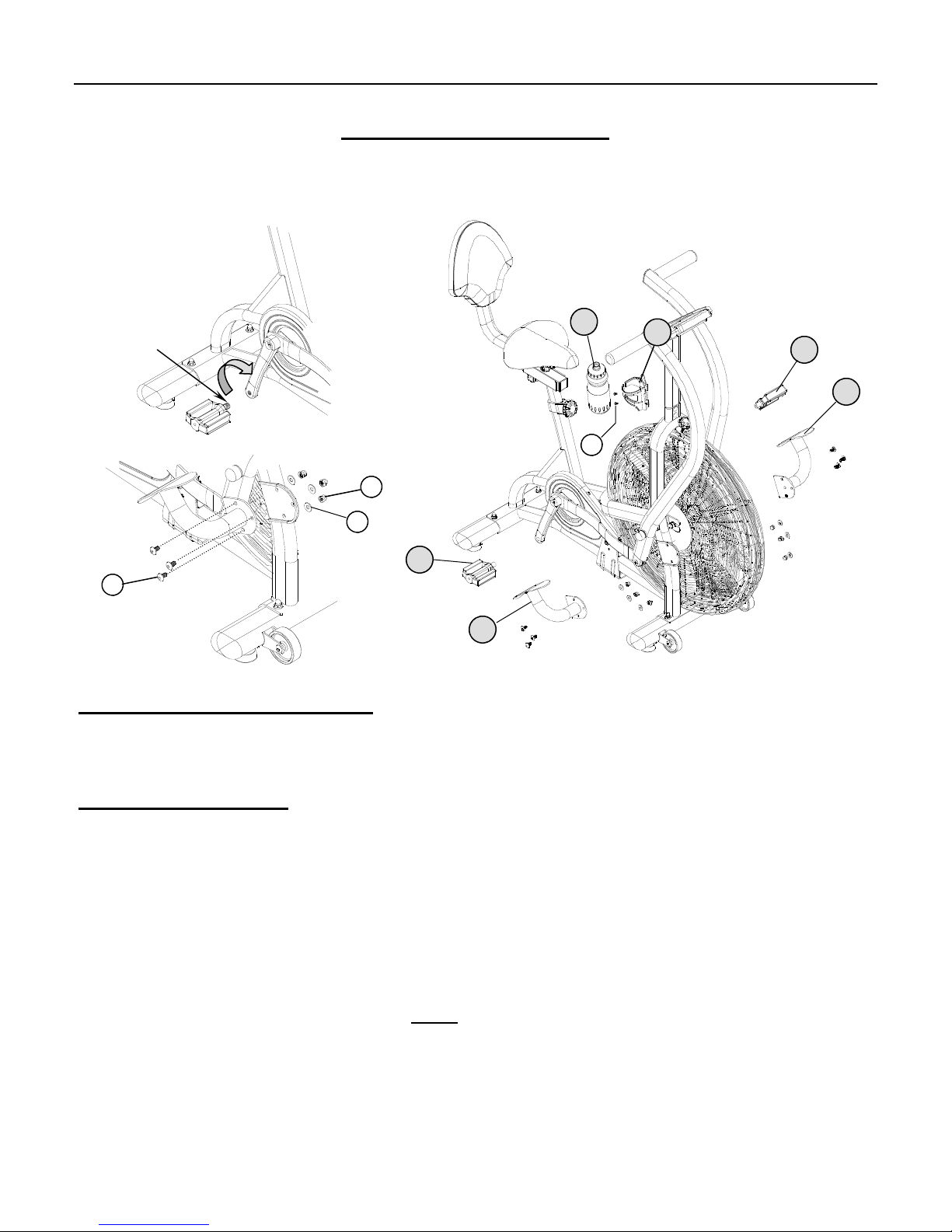
ASSEMBLY STAGE #5
Attach Pedals & Foot Rest to the Main Base Assembly
Assembly Hardware Required: (*Assembly hardware may be preinstalled)
#23 Spring Washer Qty. 6 #26 Pan Head Screw* Qty. 2
#24 Acorn Nut Qty. 6 #29 Button Head Allen Bolt Qty. 6
Assembly Description:
Assembly Note: The right and left pedals are appropriately marked (R) and (L). The threading orientation on the left pedal is
reversed from the threading orientation on the right pedal. To avoid stripping of the threads on the pedals or crank arms, make sure
to follow the proper assembly orientation.
A) Assemble the Right Pedal (#20) to the Right Crank Arm on the Main Base Assembly. Thread the pedal on the crank arm
(clockwise) and securely tighten with the pedal wrench (included). (Reference Figure #5)
B) Assemble the Left Pedal (#21) to the Left Crank Arm on the Main Base Assembly. Thread the pedal onto the crank arm
(counterclockwise) and securely tighten with the pedal wrench (included).
C) Mount the Left & Right Foot Rest (#18 & #19) to the Main Base Assembly (#1) using 3-Button Head Allen Bolts (#29), 3
-Spring Washers (#23), and 3-Acorn Nuts (#24) per side. (Reference Figure #6)
D) Mount the Bottle Cage (#35) to the Computer Mast (#6) using 2-Pan Head Screws (#26). Insert Sport Bottle (#36) into the
cage. ( Note: Washing the bottle before use is recommended)
Assembly Tip: Take time to review the additional information regarding computer operation, product maintenance, and warranty.
Congratulations !
You have successfully completed the assembly of this product and you are ready to start exercising toward a healthier lifestyle!
PAGE 8
Figure 5
Figure 6
29
23
24
21
19
20
18
36 35
26
® Right Pedal

COMPUTER OPERATION
BUTTON FUNCTIONS
BUTTON FUNCTIONS
MODE THE “MODE” BUTTON WILL SELECT AND SCROLL THROUGH EACH DISPLAY
FUNCTION.
RESET THE RESET BUTTON CAN BE USED TO ZERO OUT AN INDIVIDUAL DISPLAY
FUNCTION.
TOTAL RESET THIS BUTTON WILL ZERO OUT ALL DISPLAY READINGS AND PRESET VALUES.
NOTE: THE REMOVAL OF THE BATTERIES WILL ALSO RESET ALL DISPLAY
FUNCTIONS TO ZERO.
UP THIS BUTTON ADJUST (INCREASES) FUNCTION VALUES.
DOWN THIS BUTTON ADJUST (DECREASES) FUNCTION VALUES .
DISPLAY FUNCTIONS
DISPLAY FUNCTIONS
SPEED THE COMPUTER WILL REFERENCE A TRAINING SPEED BASED ON
CORRESPONDING PEDAL RPM.
TIME COMPUTER DISPLAY WILL ACCUMULATE TOTAL TRAINING TIME IN 00:00
(MINUTES : SECONDS). COMPUTER WILL COUNT UP TO A MAXIMUM
DISPLAY READING OF 99:99.
PRESET TARGET TRAINING TIME: USE THE “MODE” BUTTON TO SCROLL
TO TIME FUNCTION AND PRESS THE “UP OR DOWN” BUTTONS TO SET THE
DESIRED TIME. SETTINGS WILL BE ENTERED IN 1:00 MINUTE INCREMENTS
AND THE COMPUTER WILL COUNT DOWN FROM THE SET TIME. ONCE THE
DESIRED TIME IS SET, START PEDALING TO BEGIN TRAINING OR PRESS THE
“MODE” BUTTON TO CONTINUE THE TARGET SET UP OF OTHER FUNCTIONS.
DISTANCE THE COMPUTER ACCUMULATES TRAINING DISTANCE FROM 0.00 TO A
MAXIMUM OF 99.99 MILES. EACH INCREMENT WILL BE DISPLAYED IN 0.01
MILE.
PRESET A TARGET TRAINING DISTANCE: USE THE “MODE” BUTTON TO
SCROLL TO THE TIME FUNCTION AND PRESS THE “UP OR DOWN” BUTTON
TO SET A DESIRED DISTANCE. EACH SETTING WILL BE IN INCREMENTS OF
0.5 MILE AND THE COMPUTER WILL COUNT DOWN FROM THE SET
DISTANCE. ONCE THE DESIRED DISTANCE IS SET, START PEDALING OR
PRESS THE “MODE” BUTTON TO CONTINUE THE TARGET SET UP OF OTHER
FUNCTIONS.
SCAN THE COMPUTER WILL AUTOMATICALLY SCAN (CYCLE) THROUGH EACH
FUNCTION READING EVERY 5 SECONDS. THE LARGE CHARACTER
INFORMATION WILL CORRESPOND TO A BLINKING FUNCTION WINDOW AT
THE BOTTOM OF THE DISPLAY. SCAN (CYCLING) SEQUENCE; SPEED, TIME,
DISTANCE, AND CALORIES.
NOTE: THE SCAN FUNCTION CAN BE TURNED OFF DURING A TRAINING
SESSION BY PRESSING THE “MODE” BUTTON ONCE. THE SCAN SEQUENCE
CAN BE REACTIVATED BY USING THE “MODE” BUTTON TO MANUALLY
SCROLL TO THE BEGINNING FUNCTION WINDOW (SPEED READING). AT THIS
POINT, THE WORD “SCAN” WILL APPEAR IN THE UPPER LEFT CORNER AND
AUTOMATICALLY BE REACTIVATED.
PAGE 9

PAGE 10
COMPUTER OPERATION
DISPLAY FUNCTIONS
DISPLAY FUNCTIONS (Continued)
CALORIE COMPUTER ACCUMULATES TOTAL CALORIE CONSUMPTION (BURN) DURING
A TRAINING PERIOD. COMPUTER WILL COUNT IN 1 CALORIE INCREMENTS, FROM 0
TO A MAXIMUM READING OF 9999 CALORIES.
PRESET A TARGET CALORIE BURN: USE THE MODE” BUTTON TO SCROLL TO THE
CALORIE FUNCTION AND PRESS THE “UP OR DOWN” BUTTONS. SETTINGS CAN BE
ENTERED IN INCREMENTS OF 10 CALORIES AND THE COMPUTER WILL COUNT
DOWN FROM THE SET CALORIE VALUE. ONCE THE CALORIE FUNCTION IS SET,
START PEDALING TO BEGIN TRAINING OR PRESS THE “MODE” BUTTON TO
CONTINUE THE TARGET SET UP OF OTHER FUNCTIONS.
NOTE: THE REPORTED CALORIE DATA IS ONLY A REFERENCE GUIDE FOR THE USER.
IT SHOULD NOT BE USED IN COMPARISON OF CALIBRATED MEDICAL EQUIPMENT.
TRAINING NOTE: EACH FUNCTION WILL ALWAYS RESET TO A ZERO VALUE AFTER A PRESET TARGET
IS ACHIEVED. THE COMPUTER WILL AUTOMATICALLY START COUNTING UP FROM
ZERO IF A USER CONTINUES TO TRAIN (PEDAL) AFTER REACHING A TARGET
VALUE .
FEATURES
AUTO START COMPUTER WILL ACTIVATE ONCE A SENSOR SIGNAL IS DETECTED (PEDAL OR ARM
MOVEMENT).
SLEEP MODE COMPUTER WILL AUTOMATICALLY STOP DISPLAYING FUNCTION READINGS
AFTER 5 MINUTES OF NOT RECEIVING A SENSOR SIGNAL.
NOTE: START PEDALING TO REACTIVATE THE COMPUTER.
TIME & TEMP THE COMPUTER WILL ALWAYS DISPLAY THE ROOM TEMPERATURE AND
TIME WHEN THE OTHER FUNCTIONS ARE NOT IN USE OR COMPUTER IS IN A
SLEEP MODE.

PAGE 11 TROUBLESHOOTING
BASIC TROUBLESHOOTING TIPS
BASIC TROUBLESHOOTING TIPS
PROBLEM DESCRIPTION SUGGESTED SOLUTION
NO DISPLAY 1) CHECK BATTERY ORIENTATION: + / -
2) CHECK BATTERY VOLTAGE: (2) AA BATTERIES 1.5 VOLTS EACH
3) CHECK CABLE CONNECTIONS: MAKE SURE CONNECTIONS ARE
SECURE AND IN THE CORRECT ORIENTATION.
4) CHECK CABLE ASSEMBLIES FOR DAMAGE: PINCH POINTS &
POSSIBLE SHORTING OF WIRES.
5) CHECK FOR POSSIBLE COMPUTER DAMAGE: CRACKED DISPLAY
WINDOW (BLACK SCREEN).
*If computer still fails to operate after checking these suggestions,
contact us for technical support.
PRODUCT WILL NOT SIT LEVEL 1) USE LEVELERS ON THE BOTTOM OF THE STABILIZERS TO ADJUST
EQUIPMENT TO UNEVEN SURFACES.
SEAT POST MOVEMENT 1) MAKE SURE THE ADJUSTMENT KNOB IS LOCKED INTO A SEAT
POST HOLE.
2) SECURELY TIGHTEN THE SEAT POST IN PLACE BY TURNING THE
ADJUSTMENT KNOB.
PEDAL WOBBLE 1) CHECK TO MAKE SURE PEDALS ARE INSTALLED CORRECTLY
(ORIENTATION) AND MOUNTED FLUSH WITH THE CRANK ARMS.
2) LOOSEN THE PEDALS, CHECK FOR POSSIBLE CROSS-THREADING
OF CRANK ARMS.
NO SPEED READING 1) CHECK COMPUTER CONNECTION: MAKE SURE CONNECTORS ARE
SECURE AND IN THE CORRECT ORIENTATION.
2) CHECK SPEED SENSOR. CONFIRM CABLE CONNECTION AND
ALIGNMENT WITH MAGNET.
Make sure to reference the assembly steps & parts information in this manual when performing any troubleshooting.
If you experience other technical problems that are not listed or have additional questions, please contact the original
retailer or call us at 1-888-678-2476.

PREVENTATIVE MAINTENANCE PAGE 12
E
EQUIPMENT
QUIPMENT M
MAINTENANCE
AINTENANCE
Use a dampened soft-cloth to wipe equipment free of perspiration after each use. Avoid getting
excessive moisture on computer or electronic components. Do not use abrasive cleaners or
petroleum-based solvents to clean equipment.
Do not remove drive train shrouds or attempt any technical service on equipment without consulting
an authorized service representative.
Regularly inspect product for lose assembly hardware and worn components.
(If applicable) For added safety, unplug equipment from the wall socket when it is not being used.
Use a product /exercise mat underneath equipment for protection of floors & carpets.
(If applicable) Apply recommended component lubricants at the required time periods.
Keep product assembly manual, purchase receipt, and service records in a safe storage place.
( If applicable) Periodically check batteries for proper voltage output & replace as needed.
Do not store or use equipment outdoors.
Moving equipment:
Lift up the rear stabilizer and carefully tip the bike forward until the front stabilizer wheels touch
the floor. Do not use the computer or pivot arms to move the unit. You may wish to lock the fan in
place (which will keep the arms from moving), by turning the safety knob (referenced on page 7)
until it makes contact with the fan wheel.
TRAINING FOR SUCCESS
TRAINING FOR SUCCESS
How you start an exercise program depends on your physical condition. If you have been inactive
for awhile or you have pre-existing health condition, you should start slowly. Initially you may only
be able to exercise for a short amount of time using minimal resistance levels or weight loads.
Begin your desired training program slowly and gradually increase the amount of time you
exercise. Apply realistic goals, that have been set by you or your physician. You should see
sufficient gains in your personal fitness level within 6-8 weeks of continuous exercise, but do not be
discouraged if it takes longer. It is very important to exercise at your own pace and become
confident in obtaining your goals. It is also important to apply warm-up, stretching, and cool down
periods with any exercise program.
As your fitness level increases, so will your confidence and sense of accomplishment. Regular
exercise and a healthy diet will energize you and offer a sense of well-being.

General Terms & Conditions
All StairMaster® exercise products are warranted to be free from
defects in materials and workmanship under the terms of
recommended use and warranty coverage.
Warranty coverage is valid to the original retail purchaser and is not
transferable. Coverage will be calculated from the date of retail
purchase. Original proof of purchase and serial number identification
will be required with any associated warranty claim.
Coverage periods & warranty terms may vary per product model.
Applied warranties will be based on type of product, components,
and recommended application (use environment). Products sold or
placed in non-recommended user applications will void all warranty
coverage set forth by StairMaster.
Coverage Periods
StairMaster hereby extends the following limited warranties for the
application, components, and time periods indicated:
User Environment: Residential Light Commercial
Structural Frame: 10 years (limited) 5 years (limited)
Mechanical Parts: 3 years 2 years
Electronic Parts: 1 year 1 year
Wear Items*: 6 months 6 months
Labor**: 1 year 1 year
*Wear items are those components that may need replacement based
on normal wear & tear conditions (i.e. cables, upholstery, grips, etc.).
**Labor coverage excludes unauthorized repairs, service calls, and
non-warranty related charges.
Exclusions & Limitations
Applied warranties are exclusive to StairMaster.
Warranty coverage will not extend to any product not purchased from
StairMaster or from an authorized reseller.
Warranty coverage is void and will not extend to; a) use of product in
non-recommended environments ; b) invalid claims and / or; c) any
damage, failure or loss due to improper assembly / installation,
improper maintenance, negligence, misuse, unauthorized repair,
alteration, accident, normal wear & tear, or an ACT OF GOD.
Except as expressly set forth in the stated warranty terms
StairMaster makes no other warranties, expressed or implied
including, but not limited to, any implied warranties of merchant-
ability and fitness for a particular purpose. Any implied
warranties that may be imposed by law are limited to the terms
stated within StairMaster® product warranties. Neither
StairMaster nor any of its affiliates will be responsible for
incidental or consequential damages.
Some states do not allow limitations on how long an implied
warranty lasts or the exclusion or limitation of incidental
or consequential damages, so the preceding exclusions or limita-
tions may not apply. The stated warranty gives you specific legal
rights and you may have other rights that vary state to state.
StairMaster neither assumes or authorizes anyone to assume for
it any other express warranty.
Exclusive Remedies
For any product that fails to conform under the terms of applied
warranty, StairMaster will provide, at their option, one of the
following: 1) repair or replacement of defective parts, or
2) replacement of equipment with a product of equal value; 3)
limited credit reimbursement toward another StairMaster® product.
Service Procedure
Obtain warranty service by contacting StairMaster or the original
place of product purchase. Warranty service will be performed by the
original reseller or an authorized service provider.
All warranty claims must be validated and meet the requirements
set forth by StairMaster. Warranty claims will include confirmation
of model number, serial number, and all pertinent information
supporting the existence of an alleged defect.
All non-warranty related service cost will be the sole responsibility of
the purchaser.
Purchaser is responsible for all transportation of product to and from
the reseller. Service calls & travel fees are not covered under standard
warranty labor and are the responsibility of the purchaser.
Unauthorized repairs, service performed by someone other than an
authorized service provider, and / or use of unapproved replacement
parts will void warranty coverage.
Note to Authorized Warranty Service Providers:
Warranty labor reimbursement or warranty parts rights may not be
transferred or reassigned to a third party service provider without the
authorization of StairMaster.
Product Registration
Fill out the enclosed warranty registration form and return to
StairMaster within 30 days of product purchase. You
can also register your product online. Along with product registration,
keep copies of all product information for your personal records.
Product Information
Model:_______________________ Purchase Date:_____________
Serial Number:___________________________________________
Contact Information:
Address: StairMaster
Phone: 1-888-678-2476
LIMITED WARRANTY
PAGE 13

Please Cut Along This Line
Thank you for purchasing a StairMaster® product. Our products are designed and manufactured to the
highest quality standards. We are committed to our customers satisfaction and we will do everything we can under the con-
ditions of your product warranty to keep you secure in your product purchase. To help us serve you better, please fill out
this Product Registration form & return it to us within 30-days of product purchase.
Send completed registration form to: StairMaster
8000 NE Parkway Drive, Suite 220
Vancouver, Washington 98662
Thank you ! We appreciate your response. The information provided on this questionnaire is used exclusively by StairMaster and will not be
distributed to any other individuals or agencies regardless of purpose.
Safety Recommendations: Consult a physician or health professional before starting any type of exercise program. Warm up and stretch before
staring a exercise routine. Inspect your product for proper assembly. Make sure all assembly hardware is tightened appropriately. Check cables and
all moving parts for smooth movement and full range of motion. If you are unsure of proper use of your purchased product, contact a local retailer
or call us for instruction. Equipment is not designed for the use of children or minors. Failure to follow or apply these suggested safety tips may
result in serious injury.
PRODUCT REGISTRATION PAGE 14
______________________________________________________________
Your Name
______________________________________________________________
Address Apt. #
______________________________________________________________
City
______________________________________________________________
State Zip Code
Phone Number: ________________________________________________
Email Address:_________________________________________________
PRODUCT INFORMATION
Model:________________________________________________________
Product Type:__________________________________________________
(Home Gym, Upright Bike, Free Weight etc.)
Serial Number:_________________________________________________
Date of Purchase:_______________________________________________
(Month / Day / Year)
Purchased From:_______________________________________________
(Retailer Name)
Address: ______________________________________________________
SURVEY
A) How did you learn about our products?
1. ƑRecommendation of personal trainer
2. ƑRecommendation of retail salesperson
3. ƑRecommendation of friend / relative
4. ƑArticle in magazine / newspaper
5. ƑInternet
6. ƑTV / radio
7. Ƒother:______________________________________________________
B) Please note all factors that influenced your product purchase:
1. ƑValued priced 5. ƑStrength training
2. ƑQuality / durability 6. ƑCardiovascular fitness
3. ƑBrand name 7. ƑWeight loss
4. ƑDesign / look / feel 8. ƑHome fitness convenience
C) Rate the overall in-home assembly of the product:
ƑFair ƑAverage ƑExcellent
D) Rate the satisfaction with the retailer from which you purchased your product:
ƑFair ƑAverage ƑExcellent
E) What other types of exercise equipment do you own?
1. ƑTreadmill 5. ƑUpright bike
2. ƑStepper 6. ƑRecumbent bike
3. ƑElliptical 7. ƑFree weights
4. ƑHome Gym 8. Other:____________________________
F) What product features / functions are most important to you?
1. ƑHeart rate monitoring 6. ƑDesign / appearance
2. ƑMultiple user programs 7. ƑEase of assembly
3. ƑEase of use 8. ƑWarranty & service
4. ƑQuality / durability 9. ƑBrand recognition
5.ƑComfort / fit / feel 10. Other:___________________________
G) How many times a week do you exercise?
Ƒ1-2 times Ƒ3-4 times Ƒ4-5 times Ƒ6-7 times
H) What is the duration of your workout?
Ƒ20-30 minutes Ƒ1-2 hours Ƒ2 hours or more
I) Age Group:
Ƒ18-25 Ƒ26-35 Ƒ36-45 Ƒ46-55 Ƒ56-65 Ƒ66 & older
J) Gender: ƑMale ƑFemale
K) Type of use: ƑPersonal ƑSpouse ƑFamily
L) Do you belong to a health club, gym, wellness center, etc.?
ƑYes ƑNo

www. stairmaster. com
StairMaster
8000 NE Parkway Drive, Suite 220
Vancouver, WA 98662
1-888-678-2476
Other manuals for StairMaster Zephyr
1
Table of contents
Other Stairmaster Exercise Bike manuals


Popular Exercise Bike manuals by other brands


Pro Fitness
Pro Fitness EB2000 Assembly & user instructions

Fit4Home
Fit4Home KPR65850 user manual

DKN technology
DKN technology AM-3i manual

Maxxus
Maxxus SpeedBike S1 Installation & operating manual

Precor
Precor Spinner Ride Series Service manual

Keys Fitness
Keys Fitness Health Trainer 440 Upright Bike HT440U owner's manual


