Gymstick PRO20.0 User manual

PRO20.0 RECUMBENT BIKE
USER MANUAL
IMPORTANT: Read all instructions carefully before using this product. Retain this owner’s manual for future
reference. The specications of this product may vary from this photo, subject to change without notice.

2PRO20.0 RECUMBENT BIKE
BEFORE YOU BEGIN
Thank you for choosing the Gymstick PRO20.0 Recumbent Bike. We take great pride in producing
this quality product and hope it will provide many hours of eective exercise to make you feel
better, look better and enjoy life to its fullest.
TABLE OF CONTENT
1. SAFETY INSTRUCTIONS.................................................................................................. 3
2. EXPLODED DRAWING...................................................................................................... 4
3. CHECK LIST....................................................................................................................... 5
4. PARTS LIST........................................................................................................................ 6
5. ASSEMBLY INSTRUCTIONS............................................................................................. 8
6. MOVING THE MACHINE.................................................................................................... 13
7 SEAT ADJUSTMENTS........................................................................................................ 13
8. CONOLE OPERATION INSTRUCTIONS........................................................................... 14
9. IMPLIED WARRANTY......................................................................................................... 20
READ AND FOLLOW THE SAFETY INSTRUCTIONS. FAILURE TO FOLLOW THESE INSTRUCTIONS
CAN RESULT IN SERIOUS INJURY.
!
NOTIFICATION!

3PRO20.0 RECUMBENT BIKE
!
WARNING!
SAFETY INSTRUCTIONS
Basic precautions should always be followed, including the following safety instructions when using
this equipment: Read all instructions before using this equipment.
1. Keep children and pets away from the machine at all times. DO NOT leave unattended children in the
same room with the machine.
2. Handicapped or disabled persons should not use the machine without the presence of a qualied health
professional or physician.
3. If the user experiences dizziness, nausea, chest pain, or any other abnormal symptoms, STOP the
workout at once. CONSULT A PHYSICIAN IMMEDIATELY.
4. Before beginning training, remove all within a radius of 2 meters from the machine. DO NOT place any
sharp objects around the device.
5. Position the machine on a clear, level surface away from water and moisture. Place mat under the unit to
help keep the machine stable and to protect the oor.
6. Use the machine only for its intended use as described in this manual. DO NOT use any other
accessories not recommended by the manufacturer.
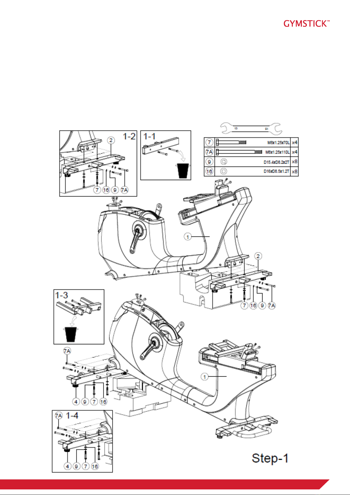
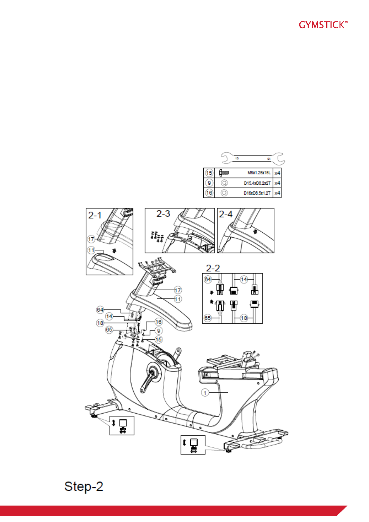
7. Assemble the machine exactly as the descriptions in the instruction manual.
8. Check all bolts and other connections before using the machine for the rst time and ensure that the
trainer is in the safe condition.
9. Hold a routine inspection of the equipment. Pay special attention to components which are the most
susceptible to wear o, i.e. connecting points and wheels. The defective components should be replaced
immediately. The safety level of this equipment can only be maintained by doing so.
10. NEVER operate the machine if it is not functioning properly.
11. This machine can be used for only one person’s training at a time.
12. Do not use abrasive cleaning articles to clean the machine. Remove drops of sweat from the machine
immediately after nishing training.
13. Always wear appropriate workout clothing when exercising. Running or aerobic shoes are also required.
14. Before exercising, always do warm-up and stretching rst.
15. Maximum user weight: 180 kg.
BEFORE BEGINNING THIS OR ANY EXERCISE PROGRAM, CONSULT YOUR PHYSICIAN FIRST.
THIS IS ESPECIALLY IMPORTANT FOR INDIVIDUALS OVER THE AGE OF 35 OR PERSONS WITH
PRE-EXISTING HEALTH PROBLEMS.

4PRO20.0 RECUMBENT BIKE
EXPLODED DRAWING

5PRO20.0 RECUMBENT BIKE
CHECK LIST

6PRO20.0 RECUMBENT BIKE
PARTS LIST
No. Description Qty.
1 Main frame 1
2 Rear stabilier 1
3Adjustable wheel 4
4Front stabilizer 1
5Front stabilizer cover 2
6 Allen bolt M8*1.25*40L 2
7Hex bolt M8*1.25*70L 4
7A Hex bolt M8*1.25*110L 4
8Curved washer D22xD8.5x1.5T 4
9Spring washer D15.4xD8.2x2T 12
10L Middle supporting cover(left) 1
10R Middle supporting cover(right) 1
11 Upper decorative cover 1
12 Rear cover 1
13 Seat post 1
14 Quick key cable(middle) 2
15 Hex bolt M8*1.25*15L 9
16 Flat washer D16*D8.5*1.2T 29
17 Handlebar psot 1
18 Handle pulse cable 2
19 Bracket for water bottle holder 2
20 Water bottle holder 2
21 Bearing #6004-2RS(C0) 2
22 Waved washer D27*D20.3*0.5T 1
23 Screw M3*0.5*30L 4
24 C-clip D22.5*D18.5*1.2T 2
25 Screw M3*0.5*12L 2
26 Crank axle 1
27 Belt wheel 1
28 Nylon nut M6*1.0*6T 6
29 Hex bolt M6x1.0x15L 4
30 Belt 1
31 Round magnet 1
32L Quick key cable (upper)(2) 1
32R Quick key cable(upper)(1) 1
No. Description Qty.
33 Upper cover for handle pulse 2
34 Lower cover for handle pulse 2
35L Membrane keys (+) 1
35R Membrane keys(-) 1
36 Handlebar 1
37L Quick key cable(lower)(2) 1
37R Quick key cable(lower)(1) 1
38 Screw ST4.2*15L 45
39 Bolt M5*0.8*12L 29
40 Back cover for the computer 1
41 Hex bolt M8*1.25*50L 4
42 Rear cover for handlebar 1
43 Front cover for handlebar 1
44 Flat washerD26*D21*1.5T 1
45 Crank cover 2
46 Left chain cover 1
47 Right chain cover 1
48L Left crank 1
48R Right crank 1
49 Anti-loose nut M10*1.25*9T 2
50 Screw cover D29*11.5L 2
51L&R Pedal set 1
52 Allen screw M6*1.0*15L 6
53 Flat washer D13*D6.5*1.0T 8
54 Flat washer D13*D6.5*1.0T 4
55 Self-generator system 1
56 Pin 12
57 Nut M5*0.8*5T 1
58 Screw M5*0.8*20L 1
59 Battery connecting cable 1
60 Buer bar 2
61 Chargeable battery 1
62 Connecting cable(2) 1
63 Upper computer cable 1
64 Upper computer cable 1

7PRO20.0 RECUMBENT BIKE
PARTS LIST
No. Description Qty.
65 Lower computer cable 1
66 Fixing plate(1) 1
67 End cap(round) 2
68 Controller 1
69 Seat 1
70 Dip foam 2
71L Left rear chain cover 1
71R Right rear chain cover 1
72 Handleabar 1
73 Sensor cable 1
74 Electric cable 1
75 Connecting cable 1
76 Computer 1
77 C-clip S-17(1T) 1
78 Waved washer D17*D22*0.3T 3
79 Bearing 6203-2RS 2
80 Plastic washer D10*D24*0.4T 1
82 Flat washer D28*D8.5*3T 1
83 Plastic cover D3*30L 2
84 Spring D2.2*D14*55L 1
85 Fixing plate for idle wheel 1
86 Plastic washer D50*D10*1.0T 1
87 Nut M8*1.25*6T 1
88 Nylon nut M8*1.25*8T 3
89 Sliding rail 1
90 Limiting plate for seat post 1
91 Fixing plate 2 1
92 Screw M5*0.8*15L 4
93 Enforcing plate for sliding rail 1
94 Bolt M6*1*15L 3
95 Hex bolt M8*1.25*45L 4
96 Enforcing tube for sliding rail 2 2
97 Allen screw M8*1.25*55L 2
98 Buer 4
99 Allen bolt M8*1.25*100L 2
No. Description Qty.
100 Cable plug 2
101 Wheel 2
102 Connecting tube for sliding rail 3
103 Adjustable pole 1
104 Trigger 1
105 Round cap 1
106 Allen bolt M8*1.25*25L 1
107 Allen screw M6*1.0*35L 2
108 Sleeve 1
109 Fixing plate 1
110 Spring D1.5*D10*35L 1
111 Wheel 8
112 Hex bolt M8*1.25*35L 4
113 End cap 4
114 Left cover for handlebar 1
115 Right cover for handlebar 1
116 Adjustable protective cover 1
117 Backrest adjusting tube 1
118 Hex bolt M8*1.25*25L 4
119 Backrest 1
120 Backrest decorative cover 1
121 Round cap 4
122 Bolt 4
123 Water pad 2
Allen spanner 1
Spanner 1

8PRO20.0 RECUMBENT BIKE
ASSEMBLY INSTRUCTIONS
STEP 1.
1. Throw away the xing tube including two bolts into trash. They are not the machine parts. Please refer to 1-1.
2. Take the styrfoam used in the packaging and put it under the rear frame to assemble the rear stabilizer (2) with main
frame (1) by using at washer (16), spring washer (9) and hex bolt (7 & 7A). Please refer to 1-2.
3. Throw away the xing tube including two bolts into trash. They are not the machine parts. Please refer to 1-3.
4. Raise up the front frame with styrofoam. Assemble the front stabilizer (4) with main frame (1) by using at washer
(16), spring washer(9) and hex bolts (7 & 7A). Please refer to 1-4.

9PRO20.0 RECUMBENT BIKE
ASSEMBLY INSTRUCTIONS
STEP 2.
1. We suggest two persons to assemble this step.
2. Assemble the front post (17) through the upper cover (11) and move it up. Please refer to 2-1
3. Connect the middle cable for console (64) with lower cable for console (65), and middle cable for quick button (14)
with hand pulse cable (18). Please refer to 2-2.
4. Throw away the xing plate, it is not a machine part. Please refer to 2-3.
5. Place down the upper cover (11) and match it well with the front post. Please refer to 2-4.
6. Adjust the knobs under stabilizers to make the machine as steady as possible.

10PRO20.0 RECUMBENT BIKE
ASSEMBLY INSTRUCTIONS
STEP 3.
1. Connect the console (76) with middle cable for console (64) and middle cable for quick button (14). Refer to 3-1.
2. Fix the console (76) onto the front post by using cross bolts (39). Please refer to 3-2.
3. Fix the back cover for console (40) onto the console by using bolts (39). Please refer to 3-3.

11PRO20.0 RECUMBENT BIKE
ASSEMBLY INSTRUCTIONS
STEP 4.
1. Assemble the back pad (119) with main frame by using at washer (16), the spring washer (9) and hex bolt (15).
2. Connect lower cable for quick button (2) & lower cable for quick button (1) with hand pulse cable (18). Fix the
handlebar (36) onto the frame by using curve washer (8) and bolt (41). Put the bottle holder (20) into the bracket.
3. Fix the front handlebar (72) by using curve washer (8) and bolt (41). Cover the rear protective cover for handlebar
(42).

12PRO20.0 RECUMBENT BIKE
ASSEMBLY INSTRUCTIONS
STEP 5.
1. Assemble the seat (69) onto the main frame by using at washer (16) and bolt (12).
2. Assemble pedals (51L & 51R) with cranks (48L & 48R). by twisting left pedal by counter-clockwise, right pedal
clockwise.
3. Cover the cover of front & rear stabilizer (5) and left & right handrail cover (114&115), fasten them by using the cross
bolt (39) and the cross screw (38).

13PRO20.0 RECUMBENT BIKE
MOVING THE MACHINE
SEAT ADJUSTMENT
The machine can be easily moved from one place to another by using the transportation wheels at the front. Grab the
machine from the handle at the back, and tilt the machine until the wheels touch ground.
You can adjust the seat distance by turning the seat adjustment handle counter-clockwise, and then moving the seat to
desired position and releasing the handle.

14PRO20.0 RECUMBENT BIKE
CONOLE OPERATION INSTRUCTIONS
DISPLAY FUNCTIONS
BUTTON FUNCTIONS
ITEMS DESCRIPTION
TIME Setting range: 0:00~99:00 (±1 minute)
Display range: 0:00~99:59
DISTANCE Setting range: 0.00~99.0 (±1)
Display range: 0.00~99.99
CALORIES Setting range: 0~9990 (±10)
Display range: 0~9999
PULSE Setting range: 0~30~230 (±1)
Display range: 0~230
WATTS Display range: 0~999
SPEED Display current working speed, max 99.9
RPM Display current RPM
Display range : 0~999
ITEMS DESCRIPTION
+Setting or increase the training resistance.
-Setting or decrease training resistance.
ROTARY BUTTON To conrm all setting.
STAR/STOP To start or stop workout.
RESET In setting mode or in selection mode, press to go back to initial training
mode. If keep pressing this button 2s, computer will restart.
RECOVERY To test heart rate recovery status.
BODY FAT To test body fat % when press the BODY FAT button in standby mode.

15PRO20.0 RECUMBENT BIKE
CONOLE OPERATION INSTRUCTIONS
OPERATING MANUAL
Power on
1. When powering on the device, the LED-display will display all segments, such as wheel diameter, KM or
ML, Eurasian gauge. (Image 1 & 2)
2. Enter into user selection mode, setting user’s private le U1-U4 (image 3), GENDER (image 4), AGE
(image 5), HEIGHT (image 6), WEIGHT (image 7). After setting the information, device will enter into
function selection mode: MANUAL, PROGRAM, USER PROGRAM, H.R.C, WATT.
Image 1. Image 2.
Image 3. Image 4.
Image 5. Image 6.
Image 7.
Power o
If without RPM input for 4 minutes, LED-display will be closed and the computer will be in power o -mode.
If RPM is detected again, the computer will wake up.

16PRO20.0 RECUMBENT BIKE
CONOLE OPERATION INSTRUCTIONS
MANUAL FUNCTION
By turning buttons “+” or “-” , user may set up TIME > DISTANCE > CALORIES > PULSE (image 8 - 10).
Press START/STOP without settings to start a workout, and in working period the user can adjust the
RESISTANCE LEVEL. Press START/STOP again and the computer will enter into break mode, press button
“RESET” to leave this mode.
PROGRAM FUNCTION
In this mode, there are 12 programs (P1~P12) for the user to select (image 11). When the user chooses
a PROGRAM, by turning buttons “+” or “-”, can be set the TIME (image 12). When nished setting press
“START/STOP” to start workout (in break mode the user can choose to adjust the “TIME” value). In START
status, user can adjust RESISTANCE level. During workout, press “START/STOP” and the computer will
enter into break mode, press “RESET” leave this mode.
Image 8. Image 9.
Image 11. Image 12.
Image 10.

17PRO20.0 RECUMBENT BIKE
CONOLE OPERATION INSTRUCTIONS
PROGRAM FUNCTION
All the dierent programs are shown below (P1-P12).
USER PROGRAM FUNCTION
By turning buttons “+” or “-” , the user can set PROGRAM, then press MODE/ENTER to conrm the setting
value of RESISTANCE (image 13). If the user wants to stop the setting, keep pressing MODE/ENTER
button for 2 seconds, LED-display will show last value set. While pressing MODE/ENTER button for 2
seconds, the user can set “TIME” (image14), if no value is set, press “START” to enter into working mode. In
START mode user can adjust the resistance. During the workout press “START” to enter into break mode,
then press button “RESET” leave this mode.
P1
P5
P9
P3
P7
P11
P2
P6
P10
P4
P8
P12
Image 13. Image 14.

18PRO20.0 RECUMBENT BIKE
CONOLE OPERATION INSTRUCTIONS
H.R.C FUNCTION
In H.R.C mode, the LED screen will show heart rate percentage 55%, 75%, 90% and TARGET. User may
select one of the heart rate percentages by turning “+” or “-” button (image 15). TARGET preset value is
100, user can also set the pulse value by themselves. By pressing the rotary button TIME can be set (image
16). If there is no need to set TIME, press “START/ STOP “, device will start the workout according to the
H.R.C function and show the current pulse value. If pulse is not detected, the LED-display will show as seen
in image 17. During the workout press “START” enter into break mode, then press “RESET” to leave this
mode.
WATT FUNCTION
The preset watt value is 120 (image 18). By turning “+” or “-” button, the WATT value can be set (setting
range is 10-350). When done setting, press the rotary button to set TIME (image 19), if there is no need to
set the TIME value, press “START/STOP”, resistance value will adjust automatically according to the set
target WATT value. During the workout press “START/STOP” to enter into break mode, then press button
“RESET” to leave this mode.
Image 15. Image 16.
Image 18. Image 19.
Image 17.

19PRO20.0 RECUMBENT BIKE
CONOLE OPERATION INSTRUCTIONS
RECOVERY FUNCTION
1. If there is no detected pulse input press “RECOVERY” button.
2. If there is a detected pulse input, press button to enter “RECOVERY” mode; time countdown from 00:60
to 00:00 (image 20). Screen will display your heart rate recovery status F1-F6 (image 21). F1 is the best
and F6 is the worst. User may keep exercising to improve their heart rate recovery status.
3. Press the RECOVERY button to leave this test mode.
BODY FAT FUNCTION
1. Press “BODY FAT” button to start testing your body fat (image 22 - image 24). At this time the user
should grab the hand grips correctly, computer will display the test value.
2. If any of the following situations occur, there will be an indication showing on display.
• “E-1” (image 25) - User did not put their thumb properly on the conductor. Please try again.
• “E-4” - BODY FAT advice has exceeded the setting range (5%~50%).
3. After the testing has nished, display will show both BODY FAT % and BMI (image 26, image 27).
During BODY FAT testing mode, press BODY FAT button to cancel the test and go back to continue the
previous excercise.
Image 20. Image 21.
Image 22. Image 23.
Image 24. Image 25.
Image 26. Image 27.

20PRO20.0 RECUMBENT BIKE
IMPLIED WARRANTY
The importer of this product assures that this device is manufactured with high quality materials.
The prerequisite for the implied warranty is the proper setup in accordance with the operating instructions.
Improper use and /or incorrect transportation can void the warranty.
The implied warranty for wear parts is valid for 1 year and for frame 5 years, beginning from the date of
purchase. For eventual defects please contact the dealer of this product within the guarantee period.
The warranty applies to the following parts (as far as included in the scope of delivery): frame, electronic
devices, wheels, foot straps and pedals.
The guarantee does not cover:
• Damage eected by outer force
• Intervention by unauthorized parties
• Incorrect handling of the product
• Non-compliance of the operating instructions
Note: Wear parts and expendable parts are also not covered.
The device is intended for professional use.
Manufactured for:
Gymstick International Oy
Ratavartijankatu 11
15170 Lahti, FINLAND
Devices marked with this symbol must be disposed of separately from your household waste, as they contain valuab-
le materials which can be recycled. Proper disposal protects the environment and human health. Your local authority
or retailer can provide information on the matter.
Other manuals for PRO20.0
4
Table of contents
Other Gymstick Exercise Bike manuals

Gymstick
Gymstick EB-DESK User manual

Gymstick
Gymstick 6100 User manual

Gymstick
Gymstick GB4.0 User manual

Gymstick
Gymstick MINI BIKE 2.0 User manual

Gymstick
Gymstick FTR7 INDOOR RACER User manual

Gymstick
Gymstick CRANK BIKE X4 User manual

Gymstick
Gymstick PRO FTR User manual

Gymstick
Gymstick AIR BIKE PRO User manual

Gymstick
Gymstick GB6.0 User manual

Gymstick
Gymstick VAPOR BIKE 10.0 User manual