Stairmaster MOMENTUM 3400 CE User manual
------
MOMENTUM
3400
CE/3800
RC
OWNER'S
MANUAL
__
StairMaster.
THE
RESULTS
YOU WANT'"
C40
OWNER'S
MANUAL

•
•
StairMastet:
Printed
in
the
United
States.
©
2001
StairMaster
Health
&
Fitness
Products,
Inc.
All
rights
reserved.
Corporate
Headquarters
12421
Willows
Road N.E..
Suite
100
Kirkland.
WA
98034
(800)
635-2936
(425)
823-1825
Fax
(425)
823-9490
www.stairmaster.com
PIN
25559-A
•
o
2001
StairMaster
Health
&
Fitness
Products.
Inc.
StairMaster
is
a
registered
trademark
of
StairMaster
Health
&
Fitness
Products.
Inc.
in
the
United
States
and
other
countries.
StairMaster
is
a
Rutledge
capital
company.
Page
iii

•
•
•
WARRANTY
This
is
to
certify
that
the
StairMaster"
Momentum
systems
cycle
ergometer
is
warranted
for
a
period
of
three
years
by
StairMaster
Health
&
Fitness
Products.
Inc.
to
be
free
of
all
defects
in
materials
and
workmanship.
This
warranty
does
not
apply
to
any
defect
caused
by
negligence.
misuse.
accident.
alteration.
impro~r
maintenance.
or
an
"act
of
Goa."
This
warranty
is
nontransferable
from
the
onginal
owner.
If.
within
three
years
from
the
date
of
purchase.
any
part
of
the
StairMaster
Momentum
systems
cycle
ergometer
should
fall
to
operate
properly
(except
any
accessories
or
the
battery).
contact
our
Customer
Service
Department
to
reP.qrt
the
problem.
International
customers
should
contact
their
local
distributor.
When
calling.
Rlease
be
prepared
to
provide
our
customer
service
representative
with
tile
following
Information:
•
Your
name.
shipping
address.
and
telephone
number;
•
The
model
number
of
the
inoperable
unit;
•
The
serial
number
of
the
inoperable
unit
(located
on
the
frame);
•
The
date(s)
of
purchase
for
the
inoperable
unit(s);
•
Your
billing
address.
This
information
will
ensure
that
you
are
the
only
one
ordering
parts
under
your
warranty
protection.
If
warranty
replacement
parts
are
shipped
to
you.
you
may
be
required
to
return
the
inoperable
part.
To
facilitate
this
process.
the
folfowing
policy
has
been
established:
•
Please
call
our
Customer
Service
Department
to
receive
a
Return
Materials
Authorization
(RMAl
prior
to
shipment.
•
StairMaster
Health
&
Fitness
Products.
Inc.
will
incur
all
freight
(i.e
..
shipping
and
handling)
charges
for
warranty
parts
ordered
for
a
product
that
is
less
than
45
days
ola.
The
parts
willoe
shipped
to
you
via
an
overnight
courier.
•
The
customer
is
responsible
for
freight
charges
on
warranty
parts
for
products
that
are
more
than
45
days
old.
Customers
will
not
be
responsible
for
the
return
shipment
of
the
inoperable
parts
(see
below).
•
Some
ino~rable
warranty
parts
must
be
promptly
returned
to
our
Customer
Service
Department.
We
will
pay
the
snipping
cost
for
the
inoperable
warranty
parts.
Detailed
instructions
are
included
with
each
warranty
replacement
part
shipment.
StairMaster
Health
&
Fitness
Products.
Inc.
neither
makes.
assumes.
nor
authorizes
any
representative
or
other
person
to
make
or
assume
for
us.
any
other
warranties
whatsoever.
whether
expressed
or
implied.
in
connection
with
the
sale.
service.
or
shipment
of
our
products.
We
reserve
the
right
to
make
changes
and
improvements
in
our
products
without
incurring
any
obligation
to
similarly
alter
products
previously
purchased.
In
order
to
maintain
your
product
warranty
and
to
ensure
the
safe
and
efficient
operation
of
your
StairMaster
Momentum
systems
cycle
ergometer.
only
authorized
replacement
parts
can
be
used.
This
warranty
is
void
ifany
parts
other
than
those
provided
by
StairMaster
Health
&
Fitness
Products.
Inc.
are
used.
•
Note:
Aerosol
products
cannot
be
transported
via
air.
Pageiv

•
•
•
PREFACE
The
StairMasterill>
Momentum
systems
cycle
ergometer
is
a
safe
and
effective
way
to
develop
aerobic
fitness
while
conditioning
the
major
muscles
of
the
lower
body.
In
order
to
get
the
best
results,
and
to
keep
your
machine
in
peak
operating
condition,
you
should
carefully
read
and
follow
the
guidelines
presented
in
this
manual.
WHAT
IS
IN
THIS
MANUAL?
This
manual
includes
sections
on
safety,
installation.
operating
instructions.
preventive
maintenance.
and
detailed
information
on
troubleshooting
and
repair
procedures.
An
appendix
at
the
end
of
the
manual
provides
important
phone
numbers
and
drawings.
WHAT
IS
THE
STAIRMASTER
STRATUS
CYCLE
ERGOMETER?
The
Momentum
systems
cycle
ergometers
have
20
levels
of
intensity
for
each
exercise
program.
The
Momentum
uses
a
variable
resistance
system
to
maintain
constant
power
within
any
given
intensity
level.
The
resistance
decreases
as
you
pedal
faster
and
increases
as
you
pedal
slower.
The
variable
resistance
system
ensures
you
will
do
the
same
amount
of
work
regardless
of
how
fast
or
slow
you
pedal.
WHAT
IS
THE
BATTERY
CHARGER
USED
FOR?
Plug
in
the
battery
charger
only
to
recharge
a
weak
battery.
Exercising
on
the
Momentum
cycle
while
the
battery
charger
is
connected
will
not
damage
the
machine.
but
will
affect
the
power
output
(watts)
statistics.
Page
v
•
•
•
----------
-
CONTENTS
SAFID
GUIDELINES
_ _
..
___ 1
INTRODUCTION
_ _ _ _ _ 3
INSTALLATION
INSTRUCTIONS
_ _ _ _ 5
BASIC
OPERATING
INSTRUCTIONS
_ 6
Adjustments
6
Seat
Height
Adjustment
on
the
Momentum
3400
CE
6
Seat
Adjustment
on
the
Momentum
3800
RC
6
Foot
Strap
Adjustment
on
the
Momentum
3400
CE
7
Basic
Instructions
For
First-Time
Users
8
Begin
Exercising
8
Rest
Periods
9
Cool
down
9
GENERAL
EXERCISE
GUIDELINES
..
_
10
Setting
a
Goal
10
Flexibility
Training
10
Exercise
Principles
11
HEART
RATE
MONITORING
_
12
Heart
Rate
Input
12
Locked/Non-locked
Option
12
Error
Messages
13
TELEMETRY
HEART
RATE
_ _ _ _
14
Using
The
Transmitter
Belt
14
Maintaining
The
Transmitter
Belt
15
CONTACT
HEART
RATE
16
Contact
Heart
Rate
16
Using
The
Contact
Heart
Rate
16
MOMENTUM
SYSTEMS
CONSOLE
17
Display
Window
17
Numeric
Keypad
17
Entertainment
Keypad
17
Page
vi

,-------------------------------------
--
•
CONTENTS
•
•
Intensity
Level
Keys
17
Stop
Key
17
Workout
Statistics
19
Exercise
Program
Keypad
20
The
Quick
Start
Program
20
The
Manual
Program
20
The
Fat
Burner
Program
21
The
Aerobic
Training
Program
21
The
Speed
Intervals
Program
21
The
Constant
Heart
Rate
Program
22
The
Fitness
Test
Programs
23
Understanding
Submaximal
Exercise
Testing
23
Pretest
Screening
25
The
StairMaster~
Submaximal
Fit
Test
25
Turning
on
the
StairMaster
Fitness
Test
28
Console
Codes
29
Custom
Codes
29
Machine
Status
Codes
31
Diagnostic
Codes
31
Configuration
Codes
33
Fitness
Testing
Codes
33
MAINTENANCE
INSTRUCTIONS
34
Helpful
Hints
34
Tool
List
34
Maintenance
Records
34
Resetting
The
Maintenance
Timer
35
Preventive
Maintenance
35
Cleaning
35
Weekly
Inspection
36
Monthly
Inspection
36
TROUBLESHOOTING
GUIDELINES
39
General
Troubleshooting
Guidelines
39
Systematic
Electrical
Troubleshooting
39
Systematic
Mechanical
Troubleshooting
42
Console
Diagnostic
Tests
43
Diagnostic
Codes
43
Page
vii

•
•
•
CONTENTS
Display
Test
43
Keypad
Test
43
Serial
Port
Test
44
Alternator
Test
44
Tach
Test
45
Error
Reporting
45
Contact
Heart
Rate
46
Telemetry
(Polar-)
Heart
Rate
Test...
47
PARTS
REMOVAL
AND
REPlACEMENT
_.48
Alternator
48
Covers
49
Console
50
Handlebar
Assembly
(3400
CE)
50
Seat
(3300
CE)
51
Seat
(3800
RC)
52
Seat
Post
(3400
CE)
53
Seat
Handle
(3400
CE)
54
Seat
Track
(3800
RC
54
High
Torque
Drive
(HTD)
Belt
55
POly-V
Belt
55
Intermediate
POly-V
Pulley
Assembly
56
Pedals
57
Crank
and
Bottom
Bracket
Assembly
58
GROUNDING
INSTRUCTIONS
._
_ _ _ _
60
NOTICE
OF
FCC
COMPLIANCE
..................................•.
_
61
APPENDICES
Important
Phone
Numbers
62
Battery
Recycling
Centers
63
Figures
8-
21
65
LIST
OF
TABLES
Table
1:
Dimensions
of
the
Momentum
Cycle
Ergometer
4
Table
2:
Fitness
Rating
Norms(V02max)
28
Table
3:
Preventive
Maintenance
Schedule
38
Page
viii

•
•
•
CONTENTS
LIST
OF
ILLUSTRATIONS
Figure
1:
Major
Parts,
3400
CE
3
Figure
2:
Major
Parts.
3800
RC
4
Figure
3:
Leg
Levelers
5
Figure
4:
Transmitter
Belt..
15
Figure
5:
Momentum
Systems
Console
17
Figure
6:
StairMaster
e
Fitness
Protocol
27
Figure
7:
Grounding
System
60
Figure
8:
Cover
Fasteners
65
Figure
9:
Cover
Fastener
Location.
3400
CE
66
Figure
10:
Cover
Fastener
Location,
3800
RC
67
Figure
11:
Right
Side
View,
3400
CE
68
Figure
12:
Right
Side
View,
3800
RC
69
Figure
13:
Seat
Post
Assembly,
3400
CE
70
Figure
14:
Seat
Assembly,
3800
RC
71
Figure
15:
Seat
Track
Assembly.
3800
RC
72
Figure
16:
Intermediate
POly-V
Assembly
73
Figure
17:
Crank
Assembly
74
Figure
18:
Alternator/Flywheel
Assembly
75
Figure
19:
Wire
Connections
76
Figure
20:
Power
Control
Board
Plug-ins
77
Figure
21:
Wiring
Diagram
78
Pageix

This
symbol
appearing
throughout
this
manual
means
Attention!
Be
Alert!
Your
safety
is
involved.
•
SAFETY
GUIDELINES
WHEN
USING
ELECTRICAL
EQUIPMENT,
ALWAYS
FOlLOW
THESE
BASIC
PRECAUTIONS:
IMPORTANT
SAFETY
INSTRUCTIONS
&
The
following
definitions
apply
to
the
words
"Danger"
and
"Warning"
found
throughout
this
manual:
DANGER.
Used
to
call
attention
to
IMMEDIATE
hazards
which.
if
not
avoided.
will
result
in
immediate.
serious
personal
injury
or
loss
of
life.
READ
All
INSTRUCTIONS
BEFORE
USING
THE
MACHINE.
WARNING
-
Used
to
call
attention
to
POTENTIAL
hazards
that
could
result
in
personal
injury
or
loss
of
life.
•&
DANGER
&
WARNING
To
reduce
the
risk
of
electrical
shock.
always
unplug
the
external
power
supply
from
the
electrical
outlet
before
cleaning.
maintaining.
or
repairing.
To
reduce
the
risk
of
bums.
electric
shock.
or
injury
to
persons:
•
1.
The
external
power
supply
should
always
be
unplugged
from
the
electrical
outlet
before
removing
or
installing
parts.
Never
make
adjustments
or
repairs
while
an
exercise
program
is
in
progress.
2.
Close
supervision
is
necessary
whenever
the
machine
is
used
by
or
near
children.
invalids.
or
disabled
persons.
Unplug
from
outlet
when
not
in
use.
3.
Keep
your
hands
away
from
all
moving
parts
and
keep
your
feet
on
the
pedals
while
exercising.
Do
not
operate
the
machine
with
the
side
covers
removed.
or
outdoors.
Page
1

•
•
•
SAFETY
GUIDELINES
4.
Use
this
machine
only
for
its
intended
use
as
described
in
this
Manual.
Do
not
use
parts.
attachments.
or
accessories
other
than
those
provided
by
StairMaster~
Health
&
Fitness
Products.
5.
Do
not
use
the
external
power
supply
if it
has
a
damaged
cord
or
plug.
if it
is
not
working
properly.
ifit
has
been
dropped
or
damaged.
or
dropped
into
water.
Contact
our
Customer
Service
Department
to
arrange
for
the
return
of
damaged
parts.
6.
Connect
the
external
power
supply
to
a
properly
grounded
AC
wall
outlet;
refer
to
the
"Grounding
Instructions"
section.
Keep
all
cords
away
from
heated
surfaces.
7.
To
disconnect
the
external
power
supply.
remove
the
plug
from
the
AC
wall
outlet.
8.
Never
drop
or
insert
any
object
into
any
opening
on
the
machine.
9.
Do
not
operate
where
aerosol
(spray)
products
are
being
used
.
10.
Always
wear
insulated
gloves
when
handling
batteries.
11.
Do
not
crUSh.
incinerate.
or
dismantle
the
battery.
The
electrolyte
contains
sulfuric
acid
which
can
cause
serious
damage
to
eyes
and
skin.
Should
this
occur.
flush
profusely
with
water
and
seek
medical
attention.
12.
Do
not
use
the
machine
outdoors.
The
safety
level
given
by
the
design
of
this
equipment
can
only
be
maintained
when
the
equipment
is
regularly
examined
for
damage
and
wear.
Inoperable
components
shall
be
replaced
immediately
or
the
eqUipment
shall
be
put
out
of
use
until
it
is
repaired.
Failure
to
follow
all
guidelines
may
compromise
the
effectiveness
of
the
exercise
experience.
expose
yourself
(and
possibly
others)
to
injury.
and
reduce
the
longevity
of
the
machine.
Follow
all
training
instructions
listed
in
the
manual
and/or
on
the
machine.
Physical
injury
may
result
from
incorrect
or
excessive
training.
/-
-..-
--
-.- -
--
t
.-'"
·l--~~r:-~
--
--....-----""--~
.......
~--.
~'
I.'
f
j"
I
~
r
~
to.
I :
~.
:'
'.
r '
..
,'
'\
....
)-I
....
~;#
j
1.
I
."
/.
I
.,.
-
..
<'
..
l
..
_._
..
~
._.
..
__
._.
__
._.
.
__
..
~._
~
Page
2
•
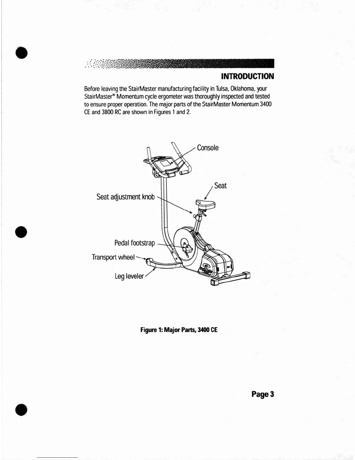
INTRODUCTION
Before
leaving
the
StairMaster
manufacturing
facility
in
Tulsa,
Oklahoma.
your
StairMaster
e
Momentum
cycle
ergometer
was
thoroughly
inspected
and
tested
to
ensure
proper
operation.
The
major
parts
of
the
StairMaster
Momentum
3400
CE
and
3800
RC
are
shown
in
Figures
1
and
2.
•
Seat
adjustment
knob
Pedal
footstrap
Transport
wheel
Leg
leveler
Console
/seat
•
Figure
1:
Major
Parts,
3400
CE
Page
3
•
----
---
-----
-----
---------
-
-----
----
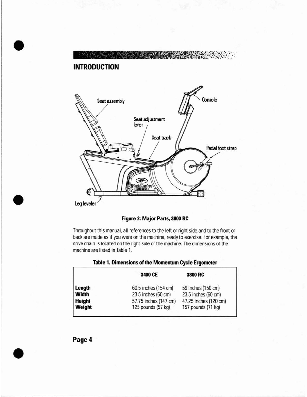
INTRODUCTION
•
Seat
assembly
/
Leg
leveler
Figure
2:
Major
Parts,
3800
RC
Console
Throughout
this
manual.
all
references
to
the
left
or
right
side
and
to
the
front
or
back
are
made
as
if
you
were
on
the
machine,
ready
to
exercise.
For
example,
the
drive
chain
is
located
on
the
right
side
of
the
machine.
The
dimensions
of
the
machine
are
listed
in
Table
1.
Table
1.
Dimensions
of
the
Momentum
Cycle
Ergometer
•
Length
Width
Height
Weight
Page
4
3400
CE
60.5
inches
(154
cm)
23.5
inches
(60
cm)
57.75
inches
(147
cm)
125
pounds
(57
kg)
3800RC
59
inches
(150
cm)
23.5
inches
(60
cm)
47.25
inches
(120
cm)
157
pounds
(71
kg)
,-----------------------------------
•
INSTALLATION
INSTRUCTIONS
Assemble
your
machine
before
use.
Machines
shipped
outside
the
United
States
need
to
be
uncrated
before
they
can
be
assembled;
refer
to
the
"Uncrating
Instructions"
included
with
your
machine
for
the
details.
1.
Remove
all
shipping
material
and
the
battery
charger
from
the
machine.
The
battery
charger
is
only
used
to
recharge
alow
battery.
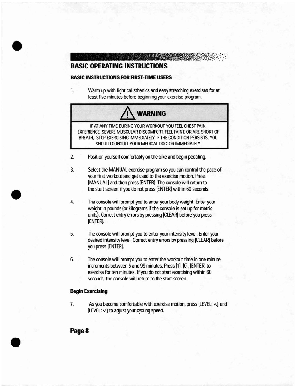
2.
Make
sure
the
machine
is
level
before
you
use
it
for
the
first
time.
Adjust
the
leg
levelers
as
necessary
to
level
the
machine
(see
below).
•
Leg
levelers
284$
Figure
3:
Leg
levelers
3.
Pedal
the
cycle
to
turn
on
the
console.
Watch
the
console,
it
should
display
the
machine
type
and
then
show
"SELECT
WORKOUT."
If
the
console
does
not.
connect
the
battery
charger
to
the
machine
and
then
plug
it
into
an
electrical
outlet.
If
the
console
powers
up,
your
battery
is
low
and
needs
to
be
charged.
Leave
the
battery
charger
connected
to
the
machine
for
24
to
48
hours
to
charge
the
battery.
It
is
okay
to
use
the
machine
with
the
battery
charger
connected.
4.
If
the
console
still
does
not
power
up
correctly,
contact
our
Customer
Service
Department.
Refer
to
the
Appendix
for
the
appropriate
phone
number.
PageS
•

•
•
•
BASIC
OPERATING
INSTRUCTIONS
ADJUSTMENTS
You
should
check
two
adjustments
before
using
your
StairMaster-
Momentum
systems
cycle
ergometer:
the
seat
and
the
pedal
foot
strap
length.
Seat
Height
Adjustment
on
the
Momentum
3400
CE
Sit
on
the
seat.
Put
both
feet
onto
the
pedals
and
into
the
foot
straps.
Pedal
slowly
and
then
stop
when
one
leg
is
extended
and
your
foot
is
as
close
to
the
floor
as
possible.
The
knee
of
the
extended
leg
should
be
slightly
bent
when
the
sole
of
your
foot
is
parallel
to
the
floor.
If
you
need
to
adjust
the
seat
height,
get
off
the
bike
and
stand
to
one
side.
The
seat
adjustment
knob
is
located
on
the
frame
tube
just
below
the
front
part
of
the
seat.
Hold
onto
the
seat
with
one
hand
and
pUll
out
on
the
seat
adjustment
knob
with
your
other
hand.
You
may
need
to
lift
up
on
the
seat
to
disengage
the
seat
pin.
Lower
or
raise
the
seat
as
necessary.
A
WARNING
------------41
TO
ELIMINATE
THE
RISK
OF
INJURY,
DO
NOT
ADJUST
THE
SEAT
HEIGHT
WHILE
SIDING
ON
THE
MOMENTUM
3400
CE
CYCLE
ERGOMETER.
MAKE
SURE
THAT
THE
SEAT
ADJUSTMENT
PIN
COMPLETELY
ENGAGES
THE
HOLE
IN
THE
SEAT
POST
BEFORE
REMOUNTING
THE
BIKE.
Seat
Adjustment
on
the
Momentum
3800
RC
Sit
on
the
seat.
Put
both
feet
onto
the
pedals
and
into
the
foot
straps.
Pedal
slowly
and
then
stop
when
one
leg
is
extended.
The
knee
of
the
extended
leg
should
be
slightly
bent.
The
seat
adjustment
lever
is
in
front
of
the
seat
base.
Remain
seated
and
keep
your
feet
on
the
pedals.
Pull
up
on
the
lever
and
slide
forward
or
backward
as
necessary.
Release
the
lever
and
make
sure
the
seat
is
locked
in
place
by
trying
to
move
the
seat
forward
and
backward.
Page
6

•
•
•
BASIC
OPERATING
INSTRUCTIONS
Foot
strap
Adjustment
To
ensure
your
feet
are
properly
secured
to
the
pedals,
you
need
to
check
the
position
of
the
foot
straps.
Position
your
foot
so
that
the
ball
of
your
foot
is
over
the
pedal
spindle.
The
pedal
foot
straps
should
be
tight
enough
to
secure
your
feet
to
the
pedals
but
not
so
tight
so
as
to
cut
off
the
circulation.
If
you
need
to
adjust
the
foot
strap
length,
get
off
the
bike
and
stand
to
one
side.
There
are
two
adjusting
holes
on
the
inside
foot
strap
mount
and
four
holes
on
the
outside
foot
strap
mount.
Most
shoes
can
be
accommodated
by
adjusting
the
outside
mounting
holes.
To
make
the
necessary
adjustments,
grasp
the
pedal
with
one
hand
and
the
outside
end
of
the
foot
strap
with
your
other
hand.
Carefully
pull
the
outside
end
of
the
foot
strap
off
the tab
on
the
pedal.
Insert
the
proper
hole
of
the
foot
strap
onto
the
pedal
tab.
If
you
need
to
make
additional
adjustments,
repeat
the
process
with
the
inside
mounting
holes
of
the
foot
strap
.
Page
7
c----------------------------------~----~-
•
BASIC
OPERATING
INSTRUCTIONS
BASIC
INSTRUCTIONS
FOR
FIRST·
TIME
USERS
1.
Warm
up
with
light
calisthenics
and
easy
stretching
exercises
for
at
least
five
minutes
before
beginning
your
exercise
program
.
.&
WARNING
IF
AT
ANY
TIME
DURING
YOUR
WORKOUT
YOU
FEEL
CHEST
PAIN.
EXPERIENCE
SEVERE
MUSCULAR
DISCOMFORT.
FEEL
FAINT.
OR
ARE
SHORT
OF
BREATH.
STOP
EXERCISING
IMMEDIATELY.
IF
THE
CONDITION
PERSISTS.
YOU
SHOULD
CONSULT
YOUR
MEDICAL
DOCTOR
IMMEDIATELY.
2.
Position
yourself
comfortably
on
the
bike
and
begin
pedaling.
4.
The
console
will
prompt
you
to
enter
your
body
weight.
Enter
your
weight
in
pounds
(or
kilograms
if
the
console
is
set
up
for
metric
units).
Correct
entry
errors
by
pressing
[CLEAR)
before
you
press
[ENTER).
•
3.
Select
the
MANUAL
exercise
program
so
you
can
control
the
pace
of
your
first
workout
and
get
used
to
the
exercise
motion.
Press
[MANUAL)
and
then
press
[ENTER).
The
console
will
return
to
the
start
screen
if
you
do
not
press
[ENTER)
within
60
seconds
.
•
5.
The
console
will
prompt
you
to
enter
your
intensity
level.
Enter
your
desired
intensity
level.
Correct
entry
errors
by
pressing
[CLEAR)
before
you
press
[ENTER).
6.
The
console
will
prompt
you
to
enter
the
workout
time
in
one
minute
increments
between
5
and
99
minutes.
Press
[1). [0).
[ENTER)
to
exercise
for
ten
minutes.
If
you
do
not
start
exercising
within
60
seconds.
the
console
will
return
to
the
start
screen.
Begin
Exercising
7.
As
you
become
comfortable
with
exercise
motion.
press
[LEVEL:
1\]
and
[LEVEL:
v]
to
adjust
your
cyci
ing
speed.
Page
8
r---------------------------
---
•
BASIC
OPERATING
INSTRUCTIONS
8.
Select
an
intensity
level
that
allows
you
to
stay
at
a
comfortable
pace.
Harder
is
not
always
better.
Exercise
at
a
level
that
is
consistent
with
your
fitness
level.
Rest
Periods
9.
You
can
stop
and
rest
as
many
times
as
necessary
for
up
to
one
minute
for
each
rest
period
during
all
programs.
To
stop,
either
press
[STOP]
or
step
off
the
machine.
Follow
the
onscreen
prompt
to
continue
your
work
out
after
a
rest
period.
Cool
Down
•
10.
When
you
are
finished
with
your
workout.
the
machine
will
slow
down
and
the
messages
"GOAL
ATIAINED",
and
then
"COOL
DOWN"
will
be
displayed.
You
can
cool
down
on
the
machine
by
continuing
to
pedal
at
a
low
intensity.
The
console
timer
will
continue
to
count
up
from
the
selected
time
to
the
console's
set
maximum
time,
and
the
intensity
level
wi
II
default
to
level
1.
For
example,
if
the
console's
time
limit
was
set
for
60
minutes
and
you
entered
a
45
minute
workout
session,
the
cool
down
period
would
last
for
15
minutes,
or
until
you
stepped
off
the
machine.
If
no
time
limit
is
set
on
the
console.
the
timer
will
count
up
to
99,
return
to
O.
and
start
counting
up
again.
Press
[STOP]
to
end
the
cool
down.
or
step
off
the
machine.
If
the
machine
is
idle
for
one
minute
during
the
cool
down.
it will
turn
off.
•
11.
You
can
also
cool
down
by
getting
off
the
machine
walking
or
stretching
for
at
least
five
minutes.
Page
9

•
•
GENERAL
EXERCISE
GUIDELINES
SETTING
A
GOAL
The
first
step
to
a
successful
exercise
program
is
to
set
realistic
goals
and
objectives.
Are
you
wanting
an
exercise
program
that
is
geared
to
build
muscle,
maintain
muscle
tone,
or
lose
weight?
In
order
to
ensure
that
you
fUlly
receive
all
the
benefits
of
a
sound
exercise
program,
you
need
to
first
identify
the
existence
(if
any)
of
risk
factors
that
may
influence
the
design
of
your
exercise
program.
Based
upon
a
comprehensive
analysis
of
your
personal
exercise
needs
and
interests,
you
should
then
develop
(or
have
developed
for
you
by
a
competent
or
trained
professional)
an
individualized
program
of
exercise
that
is
enjoyable,
easy,
and
yet
challenging.
Your
greatest
health
benefit
will
come
from
a
lifestyle
change
that
encourages
a
lifetime
of
physical
activity.
One
way
to
guarantee
success
in
reaching
your
goal
is
to
eat
correctly.
A
well-rounded
diet
provides
the
proteins,
carbohydrates,
fats,
vitamins,
minerals,
and
water
necessary
for
good
health.
If
you
are
unsure
of
your
dietary
needs,
seek
the
advise
of
your
physician,
an
exercise
professional,
or
visit
your
local
bookstore
for
more
information
on
nutrition.
FLEXIBILITY
TRAINING-
Achieving
and
maintaining
an
adequate
range
of
motion
should
always
be
objectives
of
a
comprehensive
exercise
program.
The
warm-up
phase
of
your
exercise
session
should
include
some
type
of
light
warm-up
activity
to
increase
both
your
heart
rate
and
your
body
temperature,
which
is
then
followed
by
flexibility
exercises
that
are
specifically
designed
to
stretch
the
musculature
around
your
body's
major
skeletal
joints.
Attempting
to
stretch
a
cold
muscle
can
be
dangerous
to
the
soft
tissues
surrounding
the
muscle.
No
matter
how
controlled
the
movement,
forcing
a
muscle
through
a
full
range
of
motion
(and
beyond)
without
appropriately
warming
up
is
both
unsafe
and
counterproductive.
A
general
exercise
program
for
achieving
and
maintaining
flexibility
should
adhere
to
the
following
guidelines:
•
-Frequency
-Intensity
-
Duration
Page
10
.
daily
-
to
a
position
of
mild
discomfort
-
10-30
seconds
for
each
stretch
•
GENERAL
EXERCISE
GUIDELINES
-
Repetitions
-Type
EXERCISE
PRINCIPLES-
-
2-6
for
each
stretch
-
static,
with
a
major
emphasis
on
the
low
back
and
hamstrings
area
because
of
the
high
prevalence
of
low-back
pain
syndrome
in
our
society.
The
American
College
of
Sports
Medicine
has
developed
a
position
paper
concerning
exercise
programs
for
healthy
adults
and
the
need
for
guidelines.
The
following
recommendations
concern
the
quantity
and
quality
of
(exercise)
training
for
developing
and
maintaining
cardiorespiratory
fitness
in
a
healthy
adult:
•-
Frequency
-Intensity
-
Duration
-
Mode
of
Activity
-
Rate
of
Progression
-3
to
5
days
per
week
-50%
-
85%
of
maximum
oxygen
uptake
(V0z
ma.l
-20
to
60
minutes
of
continuous
aerobic
activity
-Any
activity
that
uses
the
large
muscle
groups.
that
can
be
maintained
continuously.
and
is
rhythmical
and
aerobic
in
nature.
-Initial
Conditioning
-4
to
6
weeks;
low-
end
intensity
(40%
-
60%
VO
zma
);
low-end
duration
(15
to
20
minutes).
-Improvement
Stage
-6
weeks
to
6
months;
moderate
intensity;
moderate
duration.
-Maintenance
Stage
-6
months
plus;
moderate
to
high
intensity;
moderate
to
high
duration.
•
•
Note:
Some
of
the
materia
I
conta
ined
in
this
section
is
adapted
from
The
StairMaste~
Fitness
Handbook
2nd
Ed
..
James
A
Peterson,
and
Cedric
X.
Bryant
(editors).
Sagamore
Publishing.
1995.
Page
11

•
•
HEART
RATE
MONITORING
HEART
RATE
INPUT
Contact
heart
rate
and
telemetry
(e.g.,
Polar~)
heart
rate
signal
detection
is
available.
The
default
heart
rate
input
option
is
"BOTH
LOCKED."
If a
telemetry
signal
is
detected
first.
contact
heart
rate
signals
are
inhibited
from
being
detected
throughout
the
rest
of
the
workout
session
and
vice-versa.
There
is
also
a
short
"lock
out"
period
at
the
beginning
of
each
workout
session
during
which
the
console
first
detects
a
signal
and
then
validates
the
signal
type.
The
duration
of
this
shorter,
initial
"lock
out"
period
differs
between
telemetry
and
contact
heart
rate.
•
Telemetry
heart
rate·
after
the
initial
belt
signal
is
detected,
the
console
will
enter
a
validation
phase
in
which
four
good
heart
beat
signals
within
four
seconds
are
required
before
locking
on
telemetry
heart
rate
signals
for
the
duration
of
the
workout
session.
During
the
validation
phase
the
console
will
not
recognize
contact
heart
rate
signals
.
•
Contact
heart
rate
-
after
the
initial
contact
sensor
signal
is
detected,
the
console
will
enter
a
validation
phase
requiring
a
good
heart
beat
signal
within
10
to
15
seconds,
or
until
the
system
acquires
a
valid
signal.
During
the
validation
phase,
the
console
will
not
recognize
telemetry
heart
rate
signals.
The
console
will
display
a
beating
double
heart
icon
that
has
the
inner
heart
colored
in
while
searching
for
a
valid
signal.
Locked/Non-locked
Option
When
the
"not
locked"
option
is
selected
the
heart
rate
source
signal
is
not
fixed
during
the
exercise
(if
the
signal
is
lost.
either
input
will
be
valid).
If
the
"locked"
option
is
selected,
then
the
heart
rate
source
signal
is
locked
on
the
first
detected
signal
during
the
workout.
To
set
a
heart
rate
signal
input.
or
to
turn
off
the
heart
rate
option
all
together,
perform
the
following
steps:
1.
On
the
console
keypad,
press
[LEVEL:
A
l,
[3].
[2].
At
this
point
the
screen
will
display
"HR
INPUTS."
Press
[ENTER]
to
select
this
option.
Page
12
This manual suits for next models
1
Table of contents
Other Stairmaster Exercise Bike manuals

Stairmaster
Stairmaster Turbo Trainer User manual

Stairmaster
Stairmaster StairMaster Zephyr Reference manual

Stairmaster
Stairmaster HIIT Bike User manual

Stairmaster
Stairmaster Stratus Systems User manual

Stairmaster
Stairmaster StairMaster Zephyr Quick start guide

Stairmaster
Stairmaster Air Fit User manual
Popular Exercise Bike manuals by other brands


Proteus
Proteus PEC 3050 owner's manual

Technogym
Technogym Bike Forma user manual

Energetics
Energetics CT- 450 Assembly instruction

FF Europe
FF Europe physionics EXBK06 Original instruction manual

Horizon Fitness
Horizon Fitness S3 owner's manual

BH FITNESS
BH FITNESS G2336i Instructions for assembly and use