manuals.online logo
Brands
  1. Home
  2. •
  3. Brands
  4. •
  5. Precor
  6. •
  7. Exercise Bike
  8. •
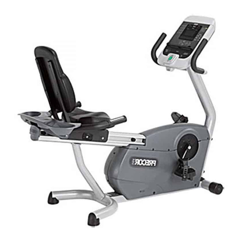
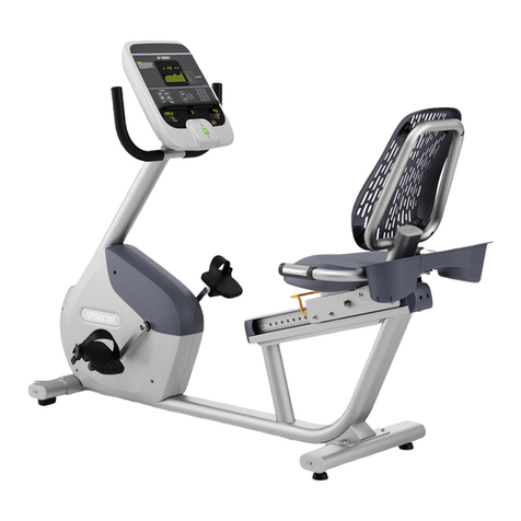
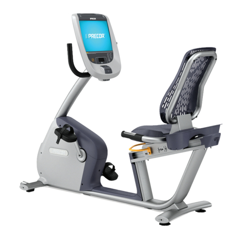
  9. Precor 600 Line RBK User manual

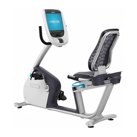
Precor 600 Line RBK User manual

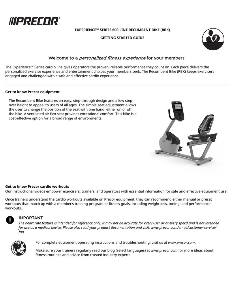
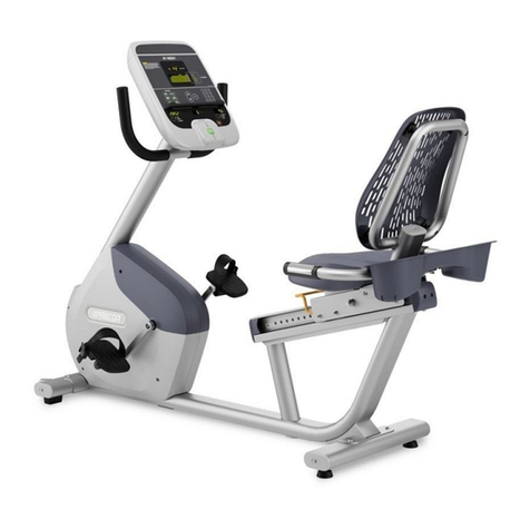
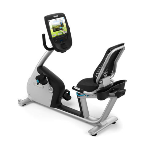
600 Line Recumbent Bike (RBK) Assembly Guide
To assemble the equipment, follow the steps in the order listed in this assembly guide. For more product information, visit us at www.precor.com.
WARNING
At least two people are required to assemble the equipment. DO NOT
attempt assembly by yourself.
We recommend you:
▪ Assemble the equipment close to where you plan to use it.
▪ Assemble the equipment on a solid, at surface, so that it remains level and stable.
▪ Locate the equipment at least 19.7 inches (0.5 meter) away from walls or furniture on
either side of the equipment, and 19.7 inches (0.5 meter) away from objects behind or in
front of the equipment.
▪ DO NOT move the equipment without assistance.
Upright support
Side cover
Top
cover
Adjustable
foot
Bottle
holder
Seat back
assembly
Rear stabilizer
Front stabilizer
Required tools and hardware
For hardware, the US English acronym is used throughout the guide and in all localized versions.
Tools Component Description Quantity Component Description Quantity
▪ 6 mm hex wrench
▪ 10 mm hex wrench
▪ 13 mm open-end, box or
socket wrench
▪ 14 mm open-end
wrench
▪ Short 3 mm ball end hex
wrench
▪ 5/32-inch ball end hex
wrench
▪ #2 Phillips screwdriver
▪ Wire cutter
▪ Fish tape
Socket head cap screw (SHCS) /
M12 x 80 mm
2 Button head cap screw (BHCS) /
M10 x 15 mm
4
Button head cap screw (BHCS) /
M10 x 40 mm
4 Washer / 5 mm 1
Button head cap screw (BHCS) /
M10 x 55 mm
2 Hex nut / M10 2
Flat head cap screw (FHCS) / 1/4-
inch x 5/8-inch (used with console)
4 Button head cap screw (BHCS) /
M5 x 16 mm
1
Attach the stabilizers
NOTE
The front stabilizer has two wheels. These wheels help to move the location of
the bike.
To install the stabilizers:
1. Place the rear stabilizer under the bracket at the rear of the bike (Figure 1).
2. Secure the rear stabilizer using two M10 x 40 mm BHCS (Figure 2). Fully tighten using a
6 mm hex wrench.
3. Place the front stabilizer underneath the bracket at the front of the bike (Figure 3).
4. Secure the front stabilizer using two M10 x 40 mm BHCS (Figure 4). Fully tighten using a
6 mm hex wrench.
Figure 1 Figure 2
Figure 3 Figure 4
Attach the seat back
IMPORTANT
DO NOT pinch the cable during this procedure.
To attach the seat back:
1. While your assistant holds the seat back assembly, feed the heart rate sensor cable into the seat
back support through the opening at its base and then out through the opening in the handlebar
bracket (Figure 5).
2. Insert the lower front edge of the seat back assembly under the seat base.
3. Position the seat back assembly so that its four screw holes line up with the holes on the seat
carriage bracket (Figure 6).
IMPORTANT
DO NOT allow the seat to slide forward or it will pinch the cable.
4. Attach it using four M10 x 15 mm BHCS and fully tighten the screws using a 6 mm hex wrench.
Figure 5
Figure 6
To complete the seat assembly:
1. Connect the heart rate sensor cable in the handlebars to the cable you fed through the
seat back in the previous procedure. Feed any extra cable back into the seat back
assembly.
2. Tilt the handlebar assembly with the handlebars slightly downward before tting it into
the slot behind the seat, making sure not to pinch the cable (Figure 7). Roll the
handlebar assembly upward so that it seats in the slot behind the seat.
3. Secure the handlebars using two M10 x 55 mm BHSC and two M10 hex nuts (Figure 8).
IMPORTANT
Gently move the cable out of the way of the screw hole. If necessary, use a dull-
edged tool inserted through the hole on the back of the handlebar assembly to
move the cable.
4. Fully tighten using a 6 mm hex wrench and a 14 mm open-end box or socket wrench.
Figure 7 Figure 8
To attach the bottle holder:
1. Move the seat back as far as it can go beyond the last latch and have your assistant hold
it in place.
2. Position the bottle holder so that the two tabs on its underside are aligned with the
bottle holder bracket.
3. Slide the bottle holder forward so that its tabs t around the bracket (Figure 9) and the
screw hole in the center of the bottle holder and the bracket line up .
4. Secure it using an M5 x 16 mm BHCS and a 5 mm at washer (Figure 10). Fully tighten
using a short 3 mm ball end hex wrench.
Figure 9 Figure 10
Attach the upright support and cables
CAUTION
DO NOT attempt to connect electrical power until all assembly procedures are complete
and properly installed.
Figure 11
To attach the upright support and cables:
1. Retrieve the cables for the console that you plan to install on this bike and for any PVS equipment that
you plan to install on the console.
2. Remove the wire tie holding the base unit data cable in place inside the upright support channel. Save
the tie for use in Step 4.
If you are installing PVS equipment on the console, continue with Step 3. If you are not installing PVS
equipment, skip to Step 5.
3. Use the wire tie from Step 1 to bind the upper ends of the cables together.
4. Feed the television and power cables through the opening at the bottom of the front stabilizer.
5. Using a sh tape, place the upright support on the oor with its lower end next to the bike. Thread the
cable(s) upward through the support and secure them to the top of the support.
6. Remove the extra serial number label from the upright support channel and set it aside for attachment
to the console mount bracket during console installation.
7. Lift the upright support and position its lower end over the upright support channel. Set the upright
support so that it rests on the metal tab within the upright support channel to prevent sliding (Figure
11).
IMPORTANT
In the following step, be extremely careful not to trap or pinch any of the cables between the
mounting screws and their seats.
8. Insert two M12 x 80 mm SHCS through the opening on the support and into the holes on the body
assembly (Figure 12). Fully tighten using a 10 mm hex wrench.
Figure 12
Level the equipment
Make sure the equipment is level before allowing anyone to use it.
CAUTION
To eliminate movement, make sure the adjustable feet are in contact with the oor. Rotating the adjustable feet cannot compensate
for extremely uneven surfaces.
To level the equipment:
1. Try to shake the equipment. If there is any movement, tip the equipment to one side to locate the adjustable foot.
2. Correct the height of each adjustable foot as follows:
If you want to ... Then turn the adjustable feet …
Raise the equipment Counterclockwise
Lower the equipment Clockwise
3. When you are nished adjusting the equipment, recheck for movement and readjust as necessary.
600 Line RBK Getting Started Guide | P/N 305386-101, ENU
© 2019 Precor Incorporated | 1 January 2019
Other Precor Exercise Bike manuals

Precor EC 850 User manual

Precor

Precor EC 850 User manual

Precor RBK 615 User manual

Precor

Precor RBK 615 User manual

Precor SPINNER RALLY User manual

Precor

Precor SPINNER RALLY User manual

Precor UBK 615 Assembly Instructions

Precor

Precor UBK 615 Assembly Instructions

Precor Experience 600 Series User manual

Precor

Precor Experience 600 Series User manual

Precor C842i User manual

Precor

Precor C842i User manual

Precor Move Beyond 846i Owner's manual

Precor

Precor Move Beyond 846i Owner's manual

Precor RBK 615 User manual

Precor

Precor RBK 615 User manual

Precor SPINNING Spinner Chrono Power Operating manual

Precor

Precor SPINNING Spinner Chrono Power Operating manual

Precor SPINNER RALLY User manual

Precor

Precor SPINNER RALLY User manual

Precor RECUMBENT RBK 800 Assembly Instructions

Precor

Precor RECUMBENT RBK 800 Assembly Instructions

Precor SPINNER SHIFT User manual

Precor

Precor SPINNER SHIFT User manual

Precor Experience 600 Series User manual

Precor

Precor Experience 600 Series User manual

Precor UBK 615 Assembly Instructions

Precor

Precor UBK 615 Assembly Instructions

Precor SPINNER RIDE User manual

Precor

Precor SPINNER RIDE User manual

Precor Teambike 800 User manual

Precor

Precor Teambike 800 User manual

Precor UBK 815 Assembly Instructions

Precor

Precor UBK 815 Assembly Instructions

Precor Spinner Chrono User manual

Precor

Precor Spinner Chrono User manual

Precor Bicycle-mounted Child Seat C846 User manual

Precor

Precor Bicycle-mounted Child Seat C846 User manual

Precor EC860 User manual

Precor

Precor EC860 User manual

Precor RBK 615 Assembly Instructions

Precor

Precor RBK 615 Assembly Instructions

Precor UBK 800 Assembly Instructions

Precor

Precor UBK 800 Assembly Instructions

Precor Experience 800 Series User manual

Precor

Precor Experience 800 Series User manual

Precor C842i User manual

Precor

Precor C842i User manual

Popular Exercise Bike manuals by other brands

Huong Dan Su Dung MK-332 instruction manual

Huong Dan Su Dung

Huong Dan Su Dung MK-332 instruction manual

Weslo Wl40230aero 800 manual

Weslo

Weslo Wl40230aero 800 manual

Proteus PEC-4350HP owner's manual

Proteus

Proteus PEC-4350HP owner's manual

Weslo 895i user manual

Weslo

Weslo 895i user manual

Weslo Pursuit R 20 Bike Manuale d'istruzioni

Weslo

Weslo Pursuit R 20 Bike Manuale d'istruzioni

SportsArt Fitness C575R Repair manual

SportsArt Fitness

SportsArt Fitness C575R Repair manual

Weslo Pursuit S 25 Exercise Bike Bedienungsanleitung

Weslo

Weslo Pursuit S 25 Exercise Bike Bedienungsanleitung

Tunturi B20 Upright X-Bike user manual

Tunturi

Tunturi B20 Upright X-Bike user manual

Giant CYCLOSMART manual

Giant

Giant CYCLOSMART manual

Weslo Pursuit T 89 Bike Manuale d'istruzioni

Weslo

Weslo Pursuit T 89 Bike Manuale d'istruzioni

Fitness Benelux virtufit user manual

Fitness Benelux

Fitness Benelux virtufit user manual

VIRTUFIT Etappe I user manual

VIRTUFIT

VIRTUFIT Etappe I user manual

Insportline Xbike Cube IN 20146 user manual

Insportline

Insportline Xbike Cube IN 20146 user manual

Horizon Fitness Comfort 3 manual

Horizon Fitness

Horizon Fitness Comfort 3 manual

Domyos VS 900 Original instructions

Domyos

Domyos VS 900 Original instructions

HOP-SPORT LEAF HS-035H instruction manual

HOP-SPORT

HOP-SPORT LEAF HS-035H instruction manual

HSE24 123526 instruction manual

HSE24

HSE24 123526 instruction manual

Sunny Health & Fitness SF-B1002 user manual

Sunny Health & Fitness

Sunny Health & Fitness SF-B1002 user manual

manuals.online logo
manuals.online logoBrands
  • About & Mission
  • Contact us
  • Privacy Policy
  • Terms and Conditions

Copyright 2025 Manuals.Online. All Rights Reserved.