5
1
Tighten this screw
temporarily so that
the screw head does
not come out.
Knife Holder
APC-45 Knife Replacement
The following procedures show how to install
new knife.
You cannot use the knife which
height is 64 mm (2.52") or shorter
byre-sharpening.
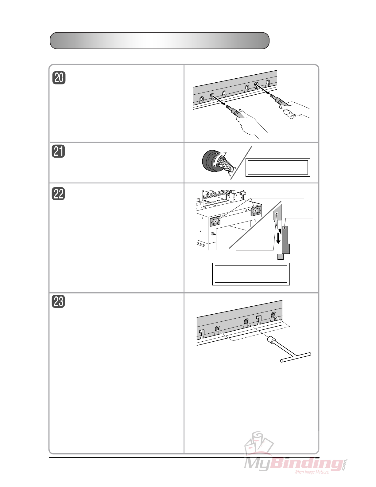
Screw the knife replacing tools in.
- Screw the knife replacing tool into the screw
holes No.2 and 5.
- Screw the knife replacing tool until 13 mm (0.52")
spaceisprovidedbetweentheknifereplacingtool
and the knife.
IMPORTANT
If the space is too much, the knife may fall.
Or if the space is too small, the knife
cannot be installed to the knife holder.
Install the knife.
1) Hold the knife replacing tools tightly and move
the knife upward slowly, then to the left along the
groove on screw hole No.2 and 5.
2) Stay the knife there and turn the knife replac-
ing tool clockwise to lock the knife.
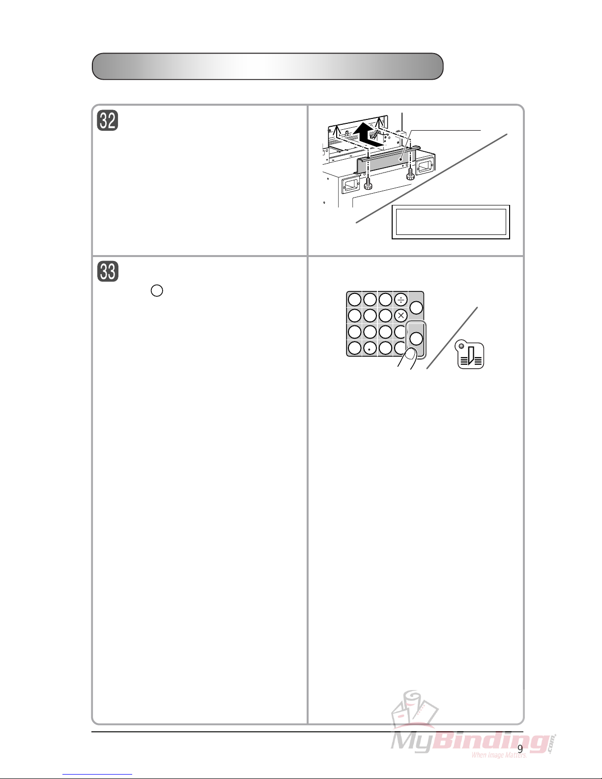
Install the fixing screws.
- Tighten the screws No.3, 4 and 6 tightly.
- Tighten the screw 1 temporarily so that the
head of the screw does not come out at least.
(This step is to lower the knife by its weight when
the fixing screws No.3, 4 and 6 are loosened in
step 23.)
14
3
2
56
14
3
2
56
64 mm (2.52") or
longer
[Reference]
Height of the new knife is
70 mm.
About
13 mm
(0.52")
New Knife
123456