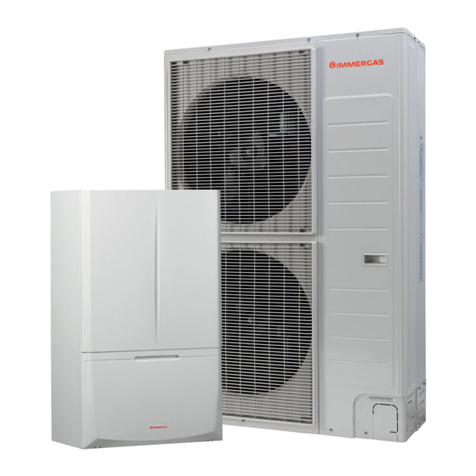
Stanley WSL141 Owner's manual

Manual for Installation, Operation
and Maintenance of Internal heat
pump units.
Models
WSL141, WSL142
The manual must be handed over to the end user after installation.

2
Content
1.
Important information ......................................................................................................... 4
1.1
Symbols.....................................................................................................................4
1.2
General......................................................................................................................5
1.3
Safety warnings and instructions.................................................................................6
1.4
Obligations of the manufacturer..................................................................................7
1.5
Obligations of the installer during installation...............................................................8
1.6
Obligations of the authorised contractor for commissioning at first commission. ..........8
1.7
Obligations of the user................................................................................................8
1.8
Factory testing............................................................................................................8
2.
Transport and installation of the device ............................................................................ 9
2.1
Transport....................................................................................................................9
2.2
Installation of the device.............................................................................................9
2.3
Storage and warehousing of the device......................................................................9
3.
Delivery.............................................................................................................................. 10
3.1
Internal unit ..............................................................................................................10
3.1.1
Hydro module SPLIT.............................................................................................10
3.2
External device.........................................................................................................11
3.3
Recycling of packaging and heat pumps at end of life...............................................11
4.
Installation of the device................................................................................................... 12
4.1
General....................................................................................................................12
4.2
Location of the device............................................................................................... 14
4.2.1
Minimal clearance from the device........................................................................14
4.2.2
Wall mounting.......................................................................................................16
4.2.3
Attachment of the indoor unit ................................................................................17
4.2.4
Removal of front cover..........................................................................................18
4.3
Connection with the external device..........................................................................19
4.3.1
Refrigeration connection - Gas and liquid connection............................................19
4.4
Hydraulic connection ................................................................................................23
4.4.1
DHW system.........................................................................................................23
4.4.2
Heating system.....................................................................................................27
4.4.3
The scheme of the heating system........................................................................28
4.4.4
Charging of the heating system.............................................................................31
4.4.5
Preparing the heating hydraulic system - secondary..............................................33
4.5
Electrical connection.................................................................................................35
4.5.1
Removal of the control unit lid...............................................................................35
4.5.2
Description of elements in electrical closet In the case of WSL141................... 36
4.5.3
Schematic display of the control system - TT3000.................................................38
4.5.4
Connecting the internal control unit –TT3000.......................................................41
4.5.5
Cable routing........................................................................................................43
4.5.6
Connection of power cable....................................................................................44
4.5.7
Connecting terminals of the communication cable.................................................45
4.5.8
Ethernet connecting terminal.................................................................................46
4.5.9
Electrical scheme..................................................................................................47

3
4.6
Connection of the spatial corrector WSL KT-1and WSL KT-2.................................... 50
5.
Commissioning of the device ........................................................................................... 51
6.
Care and maintenance ...................................................................................................... 51
6.1
Cleaning the water filter............................................................................................51
6.2
Monitoring the pressure in the heating system ..........................................................51
6.3
Cleaning of the heat conductors................................................................................51
6.3.1
Cleaning of the heating system (water section).....................................................51
6.4
Disturbances in the operation ................................................................................... 52
6.4.1
Reset of the thermal protection of the electrical heater.......................................... 52
7.
Technical data ................................................................................................................... 54
7.1
Dimensions of the device..........................................................................................54
7.1.1
WSL141, ..............................................................................................................54
7.1.2
WSL142,...............................................................................................................55
7.1.3
Technical data WSL141........................................................................................56
7.1.4
Technical data WSL 142.......................................................................................57
7.2
Noise........................................................................................................................ 59
Manual for installation, use and maintenance –Hydro module WSL141, WSL142,
This document is copyrighted. Any use outside the provisions of the copyright law without the
permission of Waterford Stanley is illegal and punishable by law. All previous versions of this document
are void. We reserve the right to make changes and printing errors.

4
1. Important information
The manual describes the process of installation and maintenance of the device. The installation and
maintenance can only be performed by qualified personnel. Read the manual carefully before the
installation, this way you will be informed about the intended use, functionality and process of handling
the device.
The manual has to be handed over to the end user after installation.
In case the product is given for use to a third person, the manual hasto be handed over to them
as well.
1.1 Symbols
These symbols mark various risks for the user or the device.
DANGER: Risk of situations which can lead to serious physical injuries.
WARNING: Risk of situations which can lead to minor physical injuries.
CAUTION: Risk of situations which can lead to damage or malfunction of the
device.
This symbol marks information for the user.
NOTE: A notice holding important information regarding requirements of the
manufacturer and the device.
Definitions
An informed person is a person who reads this manual.
A qualified person has a certificate of expert qualifications.
An authorised commission contractor is trained by the manufacturer and authorised to perform
commission.
The authorised technician is trained and authorised by the manufacturer to perform
maintenance and servicing of the device.
The user uses the device according to its use.
The installer is a person professionally trained for performing hardware and/or electric
installation work and mounting of the device.
Incorrect use of the device can lead to damage to the device, property or injury to the user. To reduce
risk, the manual points out important information with the use of symbols.

5
1.2 General
NOTE
Read the instructions for operation and installation before installation.
NOTE
Any remaking or replacement of original components of the device voids the
manufacturer’s guarantee for safe and functional operation. The
manufacturer is not responsible for the consequences and will not
acknowledge claims for damages in these cases of undesignated and
incorrect use of the device. The user is solely responsible for injuries and
damages on the device itself or on other objects resulting fromundesignated
and incorrect use of the device.
NOTE
The installation of the device has to be performed in accordance with the
manual; otherwise the manufacturer does not acknowledge the warranty.
NOTE
High pressure in heating system can cause that safety valve leak water.
Make sure the drainage pipe is open to atmospheric pressure.
CAUTION
A yearly inspection of the safety valve is necessary to ensure its proper
operation; when performing it, remove lime deposits and make sure the
safety valve is not blocked.
NOTE
The device with the mark WSL142 has a 200 litre DHW installed.
CAUTION
The drainage hole of the safety valve must be directed downwards. Make
sure it does not freeze.
DANGER
Failure to comply with the manual and good practise while connecting the
device to the power supply can lead to serious injury or death.
WARNING
Connecting the device to the power source can only be performed by a
qualified installer.

6
1.3 Safety warnings and instructions
DANGER
It is prohibited to move, shift, clean or service the device while in operation.
WARNING
It is prohibited to play with the device. Children are not allowed to clean the
device without supervision.
WARNING
The device can be operated independently only by informed persons who
are familiar with the safe operation of the device and understand possible
hazards of its operation. Children older than 8 and people with reduced
physical and mental capacities and with lack of experience and knowledge
can only operate the device under the supervision of an informed person.
WARNING
Before installation and any further adjustments to the device it is necessary
to consider the manual for safe use and maintenance.
WARNING
The installation has to be performed in accordance with national regulations
on electrical installations and with the instructions of the manufacturer. It has
to be performed by a professionally trained person.
WARNING
It has to be made sure that the device does not endanger anybody. Access
to the device has to be denied to children and persons who are not informed
about the operation of the device.
WARNING
The device must never be cleaned with cleaning agents containing sand,
soda, acid or chlorides because these might damage the surface of the
device.
WARNING
The device contains fluorinated greenhouse gas. This is why tampering with
the device is only allowed to persons authorised for working with the
refrigerant as defined by the national legislation in force. While performing
works on the device, it is necessary to prevent the refrigerant to leak into the
atmosphere.
WARNING
It is necessary to consider all technical data and instructions in this manual
as well as all warnings and notes during planning, design, installation and
use of the device.
WARNING
Electrical installations have to be inspected in accordance with regulations
on the requirements for low voltage electrical installations in buildings by a
qualified installer.

7
DANGER
Connecting the devices power cable must be performed by a qualified
electrician. The device must not be live during the procedure.
WARNING
In case the power cable of the device is damaged, it has to be replaced. The
replacement can only be performed by the installer and/or authorised
maintenance worker.
WARNING
Before opening the device, disconnect all electrical circuits and make sure
the device is not live.
CAUTION
Putting any kinds of items on or next to the device is prohibited.
CAUTION
The device must not be placed in a room where it cannot be removed. Later
walling or setting up of other obstacles next to the device is forbidden.
CAUTION
In three-phase versions of the device it is necessary to ensure the correct
arrangement of phases when connecting the device to the power supply.
CAUTION
For the correct operation of the device, the electrical distributor has to
provide electricity of adequate quality (SIST EN 50160). In normal conditions
this is within ± 10 % of the rated voltage. The data about the state of the
electrical grid may be acquired from the electrical distributor.
CAUTION
Connecting the device to the electric grid has to be performed in accordance
with the standards. The device has to be connected to the electric grid via
the power supply cut-off which isinstalled into the electricalinstallation under
the regulations in force.
1.4 Obligations of the manufacturer
The manufacturer guarantees that the device is in accordance with current European directives and
standards. The device is marked with the mark CE and it has all the necessary documentation.
We reserve the right to make changes to the manual without prior notice.
As manufacturer we do not take responsibility for the consequences arising from:
Non-compliance with the manual for the device.
Incorrect and/or inadequate maintenance of the device.
Non-compliance with the manual for the installation of the device.

8
1.5 Obligations of the installer during installation
The installer is responsible for installing the device in accordance with the following requirements:
To thoroughly study the instructions for use and installation accompanying the device before
installation.
To install the device in accordance with the instructions and national legislation, policies and
standards in force.
1.6 Obligations of the authorised contractor for commissioning at first
commission.
CAUTION
The first commissioning can only be performed by a contractor appointed by the
manufacturer in accordance with the instructions for commissioning.
The contractor is responsible for commissioning the device in accordance with the following
requirements:
Performs the first commission and with the installer of others section of heating system
eliminates all eventual irregularities found at the commission.
To train the user for operating the device and settings.
Alerts the user to regularly maintain the device for keeping the device functioning properly
throughout its entire lifespan.
Gives the user all the documentation accompanying the device.
1.7 Obligations of the user
For ensuring unobstructed and effective operation of the device the user has to follow the following
instructions:
For ensuring unobstructed and effective operation of the device the user has to follow the following
instructions:
To thoroughly study the instructions for use and installation accompanying the device before
use.
To have a qualified and authorised installer perform the installation of the device.
To have a contractor for commissions perform the commission.
Allow the authorised contractor for commissioning or ask him to thoroughly explain the
functioning and how to operate the device.
Ensure regular yearly inspections and maintenance of the device by the authorised
maintenance worker.
Store this manual in an appropriate dry place close to the device.
1.8 Factory testing
For ensuring the high quality standard every device is tested in production for the following:
Tightness of the cooling cycle,
Water-tightness
Electrical safety and
Functionality.

9
2. Transport and installation of the device
WARNING
Valves, safety elements and pipes must be checked, calculated and
determined by the system or hardware installations contractor.
WARNING
Before connecting the device, it is necessary to rinse the pipe system
thoroughly and remove impurities (solid particles, oils, greases ...).
Use suitable detergents if necessary.
NOTE
The device must be connected via closing valves.
2.1 Transport
CAUTION
The device must be transported with transport devices.
Secure the device during transport to prevent damage.
2.2 Installation of the device
CAUTION
Appropriate transport equipment must be used for installing the device. Safety regulations
and good practise have to be applied.
2.3 Storage and warehousing of the device
The device has to be stored in a dry and clean place. The allowed storage temperature is between 10
°C and 45 °C, for a short period (up to 24h) also up to 50 °C.

10
3. Delivery
3.1 Internal unit
Temperature sensor of sanitary water (Pt 1000).
Temperature sensor of 2. mixing-heating circuit (Pt 1000).
Temperature sensor of external temperature
Installation instructions.
Instructions for use.
3.1.1 Hydro module SPLIT
Hydro module
Hydro module with integrated 200
litres domestic hot water cylinder
WSL141, WSL142,
DATA LABEL

11
3.2 External device
The external unit is installed depending on the design of the heating system:
See Manual for Installation, Use and Maintenance for air–water heat pump
WSLHP7 & WSLHP11
3.3 Recycling of packaging and heat pumps at end of life.
Sort the package according to cardboard, wood and foil and dispose of it in appropriate
containers.
After the lifespan of the device ends it has to be disposed of in accordance with the legislation
on waste electrical and electronic devices and devices which contains fluorinated greenhouse
gas.
Refrigerant
The device has to be connected to the external unit holding the HFC refrigerant which is a fluorinated
greenhouse gas. You have to prevent leakage of the gas into the atmosphere. During a maintenance
procedure or removal of the device it has to be made sure that the gas is removed in accordance with
the current regulations for the use of substances harmful to the ozone and fluorinated greenhouse
gasses.

12
4. Installation of the device
4.1 General
The device is installed according to capacity
WSL141
1 Refrigerant line - for gas
2 Refrigerant line - for liquids
3 Cold sanitary water
4 Hot sanitary water
5 Return line system
6 Supply pipe system

13
WSL142
1 Refrigerant line - for liquids
2 Refrigerant line - for gas
3 Cold sanitary water
4 Circulation of sanitary water
5 Hot sanitary water
6 Supply pipe system
7 Return line system

14
4.2 Location of the device
NOTE
It is obligatory to consider the minimal clearance from obstacles for ensuring unobstructed
access for maintenance and service.
NOTE
The location of the device has to be accessible with manual transport devices to ensure
undisturbed delivery of replacement parts and equipment for maintenance and servicing.
The operator is charged costs connected with hiring special equipment for installing the
device, servicing and maintenance separately, these costs are not subject of the warranty.
NOTE
Whenyou install the deviceinto the building,make sure that you buildin a water drain which
will serve as a water drain in case of spillage.
4.2.1 Minimal clearance from the device
Minimal clearances of the external device from walls for seamless operation, maintenance and
servicing.
WSL141 Clearances
CAUTION
The devicemust not beinstalled under pipelinesbecausethereisa possibility of condensate
forming. Ingress of water condensate can cause disturbances in the operation.
NOTE
The location of theinternal devicemust bedry and in thetemperaturerange between +10 °C
and 40 °C.

15
WSL142 Clearances

16
4.2.2 Wall mounting
In the case of WSL141,
CAUTION
The wall and screw fittings must hold the weight of the device. See technical
information.
The device must be levelled
1 Hydro module 3 Wall mount
2 Screws (accessories) 4 Levelling screw

17
4.2.3 Attachment of the indoor unit
CAUTION
The indoor unit has to be screwed to the base (the screws are not part of the delivery).
1 Screws holes ɸ10 for attaching the indoor unit.
1

18
4.2.4 Removal of front cover
Removal of side WSL141,
Unscrew 4 screws of the (1)
side Open the cover lid towards yourself and push
upward
Removal of side WSL142,
First unscrew 2 screws of the
lid (A). Open the lid (A) towards yourself and push
upward. After this repeat the procedure for each
lid.
1
1

19
4.3 Connection with the external device
The connection between the internal and external device is performed via refrigerant pipes.
CAUTION
The pipeline and electrical cables have to be protected with heat and waterproof insulation
in a protective pipe. This prevents the pipe connections soaking in cases of high
groundwater or rainwater and with it intensive draining of heat into its surroundings.
4.3.1 Refrigeration connection - Gas and liquid connection
The pipe connection between the external and internal device can be made by laying the pipes in two
ways:
A inside two separate ribbed protective pipes,
B in one joint ribbed protective pipe.
A B
P16
Fill with waterproof polyurethane
foam P20
Ribbed protective pipe min. ɸ75
P17
Protective pipe for external sensors
and communication cable P21
The ribbed protective pipe for the power cable
depends on the dimension of the supply cable
P18
Copper pipe Cu P22
Ribbed protective pipe min. ɸ150
P19
Insulation min. 13 mm.
Preparation of the refrigeration pipe
Prepare the refrigeration pipe in steps. Unsuitably made joints are one of the main reasons for leakage,
the joints must thus be made thoroughly and in accordance with the listed steps.
STEP 1: Cutting of the pipe
Use a pipe cutter which does not produce chips to cut the pipe.
Determine the distance between the outdoor and indoor device.
Cut the pipe to appropriate length, and connect the internal and external device.
Make sure that the pipe after soldering / screw driving not be tense.

20
1
Copper pipe
3
Uneven
2
Inclined
4
Rough
STEP 2: Removal of chips
Remove all chips from the part where the pipe was cut.
Hold the pipe downward during cleaning so that the chips do not fall into the pipe.
In the case of WSL141, WSL142
STEP 3: Inserting the screw nut
Remove the screw nut from the pipe in outdoor unit.
Insert the screw nut into the pipe which has been cleaned.
STEP 4: Edging
The edging has to be performed with tools for edging as shown:
1
Holder
4
Cone
2
Copper pipe
5
Bracket
3
Fitting
6
Handle
7
Holder
Mount the copper pipefirmly into the tool for edging. Consider the dimensions listed in the table
below.
External diameter
‘'A''
[mm]
[inch]
[mm]
9.52
3/8
1.5 ~ 1.7
15.88
5
/8
1.6 ~ 1.8
1. Copper pipe
2. Copper pipe held downward
3. Beveler
1. Copper pipe
2. Screw nut
This manual suits for next models
1
Table of contents