Stanley DE-MC521 User manual

Delayed Egress System, Model DE-MC521
Installation Instructions
Quick-Reference Guide
204038
Rev. B 4/12/08
Prohibition on Copying
Any unauthorized reproduction, disclosure or distribution of copies by any person of any
portion of this work may be a violation of copyright law of the United States of America
and other countries, could result in the awarding of statutory damages of up to $250,000
(17 USC 504) for infringement, and may result in further civil and criminal penalties. All
rights reserved.
Stanley Access Technologies
Quick-Reference Guide

204038
Rev. B, 4/12/08
© 2008, THE STANLEY WORKS. ALL RIGHTS RESERVED. 1 of 17
Stanley Access Technologies
Quick-Reference Guide
TABLE OF CONTENTS
1. PURPOSE...................................................................................................................................................... 2
1.1 Discussion.................................................................................................................................................... 2
1.2 Applicability ................................................................................................................................................ 2
2. PREREQUISITES ......................................................................................................................................... 3
2.1 Special Items Required for Installation ....................................................................................................... 3
3. INSTALLATION INSTRUCTIONS ............................................................................................................ 4
3.1 Installing the Door Panel Components........................................................................................................ 4
3.2 Installing the Header Components............................................................................................................... 5
3.3 Installing the Components on the Header Cover or Jamb ...........................................................................5
3.4 Installing the 4-Contact Plate Assembly ( P/N: 516908) for Biparting Doors ............................................ 6
3.5 Installing the 4-Contact Plate Assembly ( P/N: 516908) for Single-Slide Doors........................................ 7
3.6 Installing the Label (P/N: 516905) .............................................................................................................. 8
3.7 Wiring the Delayed Egress Assembly ......................................................................................................... 9
3.8 Operational Checkout of the Delayed Egress System ................................................................................. 9
3.9 Troubleshooting the Delayed Egress System ............................................................................................ 10
3.10 Replacement Parts ................................................................................................................................... 11
Attachments
Attachment 1, Replacement Parts ....................................................................................................................... 12
Attachment 2, Delayed Egress Schematic Diagram (P/N 185063)..................................................................... 13
Attachment 3, Delayed Egress Wiring Diagram (P/N 185071).......................................................................... 14

204038
Rev. B, 4/12/08
© 2008, THE STANLEY WORKS. ALL RIGHTS RESERVED. 2 of 17
1. PURPOSE
1.1 Discussion
This manual provides installation instructions for the Stanley Dura-Glide Delayed Egress system
Model DE-MC521. The delayed egress system provides a controlled egress for openings which
require panic or fire hardware for safe egress. This solution has been designed to aid in loss
prevention at retail locations by denying egress for a set time period.
Setting the key function switch to the “CLOSED LOCKED” or “ONEWAY” or “REDUCED
ONE WAY” position energizes the shear magnets and secures the door in the locked mode.
Activation of the delayed egress system occurs when the panic bar is pushed and held for 1
second. (Accidentally pushing the panic bar or touching it for less than the nuisance delay time
of 1second will not sound the alarm. This nuisance delay time helps avoid inadvertent
activation.) The alarm will sound when the panic bar is pressed, but the alarm sequence will not
start unless the panic bar is held in for more than the nuisance delay time. An audible alarm
sounds after pushing the panic bar for longer than the nuisance delay. This initiates an
irreversible sequence for 15 or 30 seconds until the device releases. After the delay egress time
of 15 or 30 seconds, the lock releases and the alarm continues to sound until it is reset with
setting the key function switch to HOLD OPEN, AUTOMATIC, or REDUCED OPEN. The
individual who pushes the panic bar is denied egress for 15 or 30 seconds.
1.2 Applicability
This manual is ONLY applicable to the Stanley Dura-Glide DE-MC521 Delayed Egress system.
Standard MC521 slide installation manual is a pre-requisite for this installation manual.
Instructions for installing Transom installation, optional accessories such as access control locks,
access control consoles, key switches, door alarm contacts, push plates, and door position
switches are provided in separate installation manuals. The Transom installation and optional
accessories have not been evaluated by UL for use with the DE-MC521 Delayed Egress System.
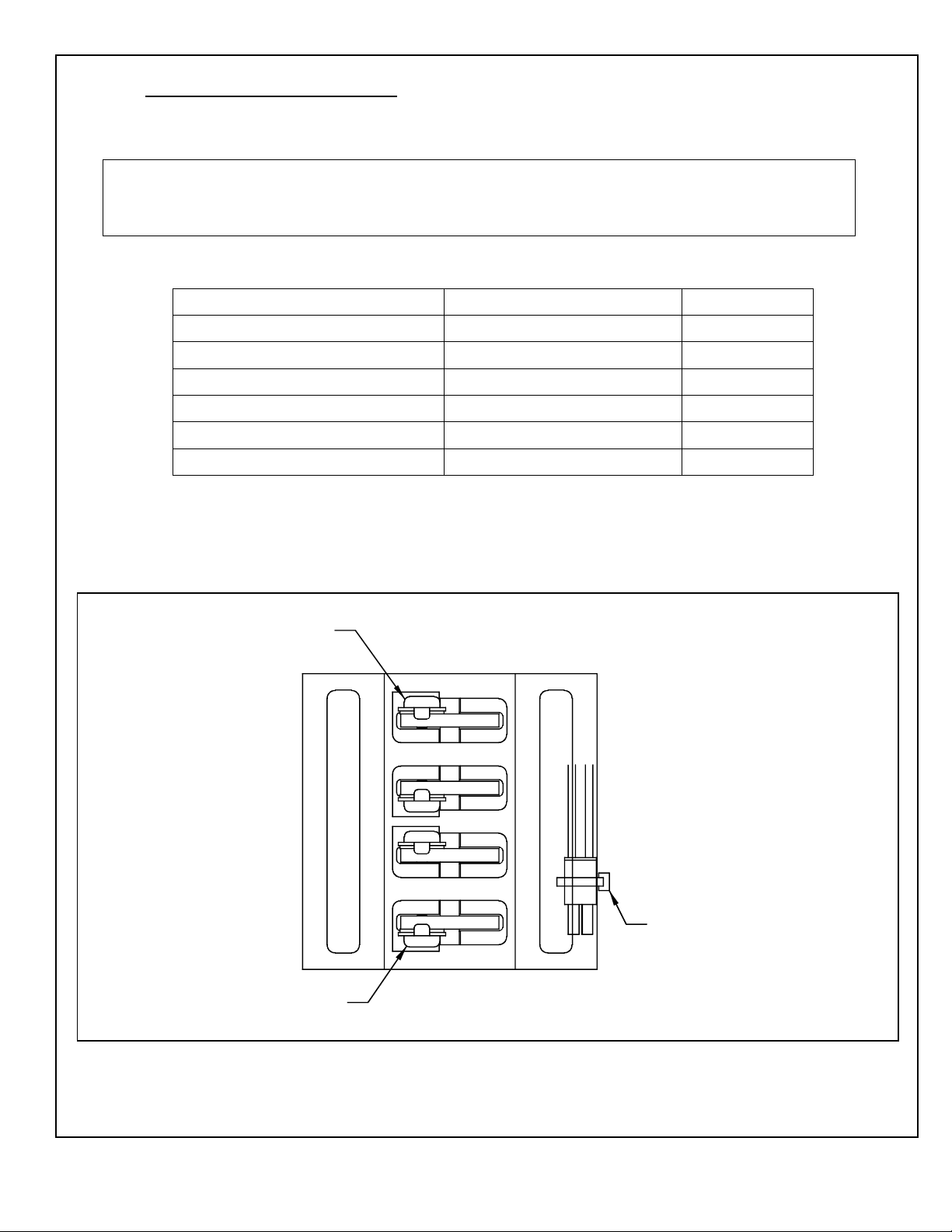
1.2.1 The delayed egress system includes the following components and functions:
•The MC521 controller mounted in the header provides the logic for the egress,
nuisance, and reset cycles
•The two UL FWAX2 Listed shear magnet locks provide locking for up to 1200
lbs of shear force. Each two-piece lock assembly includes a magnet mounted to
the underside of the hanger and an armature mounted to the top of the panel rail.
•The UL Recognized audible alarm mounted in the header connects to the MC521
controller. The input range must be greater than 20.2 Vdc.
•The four-contact assembly mounted in the center of the header transfers power
from the header to the hanger. The four-contact assembly is wired to a terminal
block assembly for shear lock control and push bar switch monitoring.
•The two-contact assembly mounted to each hanger transfers signal from the push
bar switch to the hanger when the doors are closed.
•The recessed panic bar mounted to each door panel activates the egress cycle
when pushed.

204038
Rev. B, 4/12/08
© 2008, THE STANLEY WORKS. ALL RIGHTS RESERVED. 3 of 17
2. PREREQUISITES
2.1 Special Items Required for Installation
2.1.1 UL-listed 24-VDC power supply
2.1.2 Fail-secure solenoid lock
2.1.3 Small screwdriver
2.1.4 Severence tool ( P/N: CK-3/4-45) for adding nuts to the nut track
2.1.5 Rotary/Key Switch Instruction Manual (Stanley Access Technologies Document No.
203926)
2.1.6 Power key switch assembly (P/N: 415119)

204038
Rev. B, 4/12/08
© 2008, THE STANLEY WORKS. ALL RIGHTS RESERVED. 4 of 17
3. INSTALLATION INSTRUCTIONS
3.1 Installing the Door Panel Components
NOTE
For new or retrofit installations, the door panel components shown in Table 3-1 are pre-assembled and
wired in the factory.
Table 3-1. Door Panel Components
Part Name Manufacturer Part Number
2-Contact Block Assembly Stanley Access Technologies 516909
2-Contact Plate Assembly Stanley Access Technologies 516910
4-Contact Block Assembly Stanley Access Technologies 516907
Recessed Panic Pushbar with Switch Adams Rite 185060
Detent Block for Delayed Egress Stanley Access Technologies 516906
Shear Magnet Locks GEM 714082
3.1.1 Refer to Figure 1, and, with the red wire at the top of the assembly, POSITION the 4-
contact block assembly at the lead edge of the hanger.
3.1.2 Using two #8-32 ½″pan-head screws and #8 external tooth washers, INSTALL the 4-
contact block assembly at the lead edge of the hanger.
3.1.3 Using a cable tie, SECURE the connector (and not the wires) to the tab.
Figure 1. Installing the 4-Contact Block Assembly
DE005
BOTTOM VIEW
CABLE TIE
GREEN WIRE
CONTACT
RED WIRE
CONTACT

204038
Rev. B, 4/12/08
© 2008, THE STANLEY WORKS. ALL RIGHTS RESERVED. 5 of 17
3.2 Installing the Header Components
NOTE
Table 3-2 shows the list of header components.
Table 3-2. Header Components
Part Name Manufacturer Part Number
Terminal Block Assembly Stanley Access Technologies 516913
Buzzer and Bracket Assembly Stanley Access Technologies 415109
4-Contact Plate Assembly Stanley Access Technologies 516908
DE-MC521 Controller Stanley Access Technologies 516928
3.2.1 Refer to Figure 2, and, using the nuts, clips, and screws provided, INSTALL the
following (typical) components on the track inside the header:
•DE-MC521 Controller: Replace the existing MC521 with DE-MC521 (P/N
516928)
•Terminal block assembly
•Buzzer and bracket assembly
3.2.2 SECURE all wire harnesses with cable ties.
3.3 Installing the Components on the Header Cover or Jamb
3.3.1 INSTALL power key switch assembly as follows:
•If installation is a Dura-Glide 3000, Refer to 203926, “Rotary/Key Switch
Instruction Manual,” for machining template and MOUNT power key switch
assembly P/N 415119 to header cover.
•If installation is a Dura-Glide 2000, Refer to 203926,“Rotary/Key Switch
Instruction Manual,” for machining template and MOUNT power key switch
assembly P/N 415119 to header or jamb inside of building.
Figure 2. Typical Layout for Components in the Header
HEADER
MOTOR GEAR
BOX
POWER
SUPPLY
PULLEY
SOLENOID
LOC
K
BUZZER
ASSY.
DE-MC521
CONTROLLER
TERMINAL
BLOCK ASSY.

204038
Rev. B, 4/12/08
© 2008, THE STANLEY WORKS. ALL RIGHTS RESERVED. 6 of 17
3.3.2 INSTALL rotary key switch assembly as follows:
•If installation is a Dura-Glide 3000, Refer to 203926, “Rotary/Key Switch
Instruction Manual,” for machining template and MOUNT rotary function key
switch assembly to header cover.
•If installation is a Dura-Glide 2000, Refer to 203926,“Rotary/Key Switch
Instruction Manual,” for machining template and MOUNT rotary key switch
assembly to header or jamb inside of building.
3.4 Installing the 4-Contact Plate Assembly ( P/N: 516908) for Biparting Doors
3.4.1 Refer to Figure 3, and INSTALL the 4-contact plate assembly as follows:
a. CLOSE the two doors, and ENSURE that the doors close at the center of the header.
b. MARK the center of the header onto the back of the header.
c. POSITION the 4-contact plate onto the header, and MARK the location of the
mounting holes.
CAUTION
The two top mounting holes for the 4-contact plate assembly are located above the track tube. When
drilling these two holes, use caution to ensure that the drill bit does not nick the wires located in the header
track.
d. DRILL the four mounting holes for #8-18 self-tapping screws.
e. ROUTE the 4-contact plate wire harness to the inside of the header.
f. Using the four screws provided, FASTEN the 4-contact plate to the header.
Figure 3. Installing the 4-Contact Plate Assembly for Biparting Doors
HEADER
PANEL PANEL
4 CONTACT PLATE MARK HOLES. USE # 29
DRILL
CENTER OF HEADER
HEADER
MARK HOLES. USE #29 DRILL
4-CONTACT PLATE
PANEL
PANEL
DE007

204038
Rev. B, 4/12/08
© 2008, THE STANLEY WORKS. ALL RIGHTS RESERVED. 7 of 17
NOTE
The 4-contact plate assembly must align properly with the two 4-contact switch block assemblies on the
hangers to ensure the transfer of electrical connections to the door panels. The position of the four-contact
switch block assemblies can be adjusted for vertical alignment.
3.4.2 CYCLE the door several times, and ENSURE the four-contact switch block assemblies
on the hanger leading edges mate properly with the center contact plate as the doors
come together.
3.5 Installing the 4-Contact Plate Assembly ( P/N: 516908) for Single-Slide Doors
3.5.1 CONFIGURE the 4-contact plate assembly for left side or right side mounting as
follows:
•If left side mounting, refer to Figure 4, UNSCREW the green wire from the back
of the plate, and ASSEMBLE it above the white wire.
•If right side mounting, refer to Figure 4, UNSCREW the WHITE wire from the
back of the plate, and ASSEMBLE it above the green wire.
3.5.2 Refer to Figure 5, and INSTALL the 4-contact plate assembly as follows:
a. CLOSE the DOOR.
b. Using the plate as template to mark the holes, POSITION the 4-contact plate
assembly on the header so that the dimension from the jamb to the center of the
contact plate hole is 1.8″.
Figure 4. Configuring the 4-Contact Plate Assembly for Left Side or Right Side Mounting
DE002
FINISHED
VIEW
SHOWN
MOVE FROM HERE
TO HERE MOVE FROM HERE
TO HERE
GN
BK
RD
WH
LEFT SIDE MOUTING WHEN HEADER COVER IS OPEN RIGHT SIDE MOUTING WHEN HEADER COVER IS OPEN
GN
BK
RD
WH

204038
Rev. B, 4/12/08
© 2008, THE STANLEY WORKS. ALL RIGHTS RESERVED. 8 of 17
CAUTION
The two top mounting holes for the 4-contact plate assembly are located above the track tube. When
drilling these two holes, use caution to ensure that the drill bit does not nick the wires located in the header
track.
c. Using a No. 29 drill, DRILL the four mounting holes for #8-18 self-tapping screws.
d. ROUTE the 4-contact plate wire harness to the inside of the header.
e. Using the four screws provided, FASTEN the 4-contact plate to the header.
NOTE
The 4-contact plate must align properly with the four-contact switch block assembly on the hanger to
ensure the electrical connection to the door panel. The position of the four-contact switch block assembly
can be adjusted for vertical alignment.
3.5.3 CYCLE the door several times, and ENSURE the 4-contact switch block assembly on
the hanger leading edge mates properly with the center contact plate as the door closes.
3.6 Installing the Label (P/N: 516905)
3.6.1 INSTALL the Delayed Egress label “PUSH UNTIL ALARM SOUNDS. DOOR CAN
BE OPENED IN 15 SECONDS” in the center of the push bar. (If a 30-second egress is
required and approved by fire marshal, ATTACH the “30” sticker on top of the number
“15” in the label.)
Figure 5. Installing the 4-Contact Plate Assembly for Single-Slide Doors (Left Side Mounting Shown)
HEADER
4 CONTACT PLATE
MARK HOLES. USE # 29
DRILL
PANEL
END CAP
1.8"

204038
Rev. B, 4/12/08
© 2008, THE STANLEY WORKS. ALL RIGHTS RESERVED. 9 of 17
3.7 Wiring the Delayed Egress Assembly
WARNING
All connections to the DE-MC521 controller (Part No. 516928) as indicated on the Attachment 3 must be
made by grounded, shielded cable.
Only the connections shown on the schematic in Attachment 2 have been evaluated by UL.
NOTE
The input power electrical rating for this assembly is 120-VAC, 60-Hz, and 5A. The output power
electrical rating is 14.7 ~ 20.2 VDC.
Power-limited Class 2 wiring must maintain 1/4" separation from non-power-limited Class 1 wiring.
3.7.1 Refer to Attachments 2 and 3 for the delayed egress schematic, and CONNECT system
wiring as shown.
3.8 Operational Checkout of the Delayed Egress System
3.8.1 Refer to 204003, “MC521 Installation and Operation Manual.” Perform FIS. Then SET
the door for delayed egress as follows:
NOTE
The door can be set for delayed egress using either the pushbuttons or the Palm. The following steps
describe setting delayed egress using the pushbuttons.
•INDEX 18. Value 00 is OFF (not evaluated by UL).
•INDEX 18. Value 01 is 15 sec.
•INDEX 18. Value 02 is 30 sec.
3.8.2 CYCLE the doors several times and ENSURE the following features function properly:
•The 1-second nuisance delay functions properly.
•The buzzer alarm sounds.
•The 15- or 30-second delay-of-egress period functions properly.
NOTE
The typical gap required between the magnet and the armature is 0.120″.
3.8.3 If shear locks do not engage, refer to Figure 6 and, using the key wrench supplied with
the lock kit, ADJUST the shear lock assembly. After adjusting the armature, remove the
armature and tighten nuts at the bottom. Reassemble.

204038
Rev. B, 4/12/08
© 2008, THE STANLEY WORKS. ALL RIGHTS RESERVED. 10 of 17
3.8.4 If necessary, ADJUST the 4-contact switch block assemblies and ENSURE proper
alignment with the center contact plate.
3.9 Troubleshooting the Delayed Egress System
3.9.1 Refer to Table 3-3 for a listing of symptoms and remedies.
NOTE
The following two conditions describe proper system operation:
1. Door is in CLOSED/LOCKED. The buzzer is OFF. The shear locks are energized. K1 LED is OFF. K2
LED is ON.
2. Door is in AUTOMATIC. The buzzer is OFF. The shear locks are de-energized. K1 LED is ON. K2
LED is OFF.
Table 3-3. Symptoms and Remedy
Symptom Remedy
Door set for CLOSED/LOCKED and door gets to
closed position. Delayed egress starts without
pressing push bar. The dE indication is displayed on
MC521. The buzzer turns ON. K2 LED is OFF. K1
LED is ON. And shear locks de-energize after 15/30
seconds.
Check connections from push bar switches to two-
contact transfer contacts to quad transfer contacts to
K2 coil.
Door set for CLOSED/LOCKED in closed position.
Shear locks energize, but door panel can break out.
Adjustment is required on armature. Set gap to
between 0.080″and 0.120″.
Figure 6. Adjusting the Shear Lock Assembly
ARMATURE
MAGNET
MIN. GAP
USE SUPPLIED KEY WRENCH TO ADJUST ARMATURE PLATE
TO APPROXIMATELY 0.080" to 0.120" OF GAP BETWEEN MAGNET
SURFACE. DE003

204038
Rev. B, 4/12/08
© 2008, THE STANLEY WORKS. ALL RIGHTS RESERVED. 11 of 17
3.9.2 CHECK for correct DC voltage measurements on terminal block assembly as follows:
a. SET the door to CLOSED/LOCKED.
b. CONNECT the negative (-) lead of the multimeter to TB2-10 of the DE-MC521
controller.
c. Refer to Table 3-4, and CHECK each terminal number of the terminal block and
relay assembly for the voltage shown.
Table 3-4. TB2-10 Voltage Checks
DE-MC521
TB2
Terminal
Block and
Relay Assy
Terminal No.
Voltage Possible Fault if Voltage is Incorrect
TB2-10 0 24 VDC The bridge on terminal blocks 0-1 or 2-3 is loose. Fire alarm input is
open or missing. The 24 VDC power supply disconnected.
TB2-10 1 24 VDC The bridge on terminal block 2-3 is loose. Fire alarm input open or
missing.
The 24 VDC power supply disconnected.
TB2-10 2 24 VDC The bridge on terminal block 2-3 is loose. Check 24 VDC power
supply.
TB2-10 3 24 VDC The 24 VDC power supply is disconnected.
TB2-10 4 24 VDC MC521 is selected for Fail Safe. Door position switch is not closed
TB1-7.
TB2-10 5 24 VDC The bridge on terminal block 0-1 or 2-3 is loose. Fire alarm input open
or missing.
The 24 VDC power supply is disconnected. K1 is defective.
TB2-10 6 24 VDC The bridge on terminal block 5-6 is loose.
TB2-10 7 0 VDC Wire connection open from TB5-10. Check if MC521 is configured for
delayed egress.
TB2-10 8 24 VDC Push bar switch is open. Dual transfer contact is not making
connection. Quad
Contact is not making connection.
TB2-10 9 0VDC K2 is off.
TB2-10 10 0VDC Wire disconnected from TB5-4.
TB2-10 11 0VDC Wire disconnected from TB5-10.
3.10 Replacement Parts
3.10.1 Refer to Attachment 1 for a listing of replacement parts.

204038
Rev. B, 4/12/08
© 2008, THE STANLEY WORKS. ALL RIGHTS RESERVED. 12 of 17
Attachment 1
Replacement Parts
(Sheet 1 of 1)
Description Part Number Manufacturer
Terminal Block and Relay Assembly 516913 Stanley Access Technologies
Buzzer and Bracket Assembly 415109 Stanley Access Technologies
Power Key Switch Assembly 415119 Stanley Access Technologies
4-Contact Block Assembly 516907 Stanley Access Technologies
4-Contact Plate Assembly 516908 Stanley Access Technologies
2-Contact Block Assembly 516909 Stanley Access Technologies
2-Contact Plate Assembly 516910 Stanley Access Technologies
Shear Magnet Locks 714082 GEM
Reset Switch 413584 Stanley Access Technologies
Push Bar Cartridge with Switch 185060 Adams Rite Mfg. Co.
DE-MC521 Controller Replacement
Kit
314063 Stanley Access Technologies

204038
Rev. B, 4/12/08
Page 13 of 17
© 2008, THE STANLEY WORKS. ALL RIGHTS RESERVED.
Attachment 2
Delayed Egress Schematic Diagram (P/N 185063)
(Sheet 1 of 1)
-
RELAY K1
SOL. LOCK CONTROL
DUAL TRANSFER
CONTACT
SHEAR LOCK
DUMMY PUSH BAR
WITH SWITCH 24 VDC
POWER SUPPLY
RELAY
K2
SHEAR LOCK CONTROL
SW1 SW2 +
EGRESS ENABLE CONTACT
DUMMY PUSH BAR
WITH SWITCH
24 VDC OUTPUT
24 VDC INPUT
BUZZER
TB5-3 (EGRESS ENABLE)
DUAL TRANSFER
CONTACT
SHEAR LOCK
TB1-10 (0 VDC)
TB1-9
TB1-5 (BUZZER CONTROL)
SHEAR LOCK CONTROL
DUMMY PUSH BAR RELAY
FIRE ALARM INPUT
OR JUMPER
TERMINAL BLOCK
TB5-4 (COMMON)
TB5-10 (SHEAR LOCK
CONTROL)
DE- MC521
CONTROL BOX
P/N: 516928
TB1-1 (+15 VDC)
QUAD TRANSFER CONTACTS
BRIDGE
TB2-10
TB2-9
OPTIONAL
RESET SWITCH
BRIDGE
1
2
3
4
5
6
7
8
9
10
11
A1
A2
22
21
14
11
A1
A2
NC
C
NO
C
TB1-8 (SOLENOID LOCK CONTROL)
OR
RD
RD
RD
RD
BK
BK
BK
BL
GN
GN
GN
WH
WH
WH WH
WH
WH
0
BRIDGE
TB1-2 (+24 VDC)
RD
BK
RD
12
GN
GN GN GN
WH
WH
WH
WH
GN
CHASIS
GROUND
WH
WH
WH
WH
GN
GN
GN
GN
INTERNALLY
CONNECTED
DE004
BL
GN
WH
RD
BK
RD
RD
BK

204038
Rev. B, 4/12/08
Page 14 of 17
© 2008, THE STANLEY WORKS. ALL RIGHTS RESERVED.
Attachment 3
Delayed Egress Wiring Diagram (P/N 185071)
(Sheet 1 of 4)
BUZZER AND
BRACKET ASSEMBLY
4- CONTACT PLATE
ASSEMBLY
P/N 516908
2-CONTACT BLOCK
ASSEMBLY
P/N 516909
INSTALL 1 JUMPER ON
2 INNER POSTS FOR 24 VDC
DE001_1
NOTE
THE INPUT ELECTRICAL POWER RATING FOR THIS
ASSEMBLY IS 120-VAC, 60-Hz, 5A. THE OUTPUT POWER
ELECTRICAL RATING IS 14.7~ 20.2 VDC.
POWER-LIMITED CLASS 2 WIRING MUST MAINTAIN 1/4"
SEPARATION FROM NON-POWER-LIMITED CLASS 1 WIRING.
DE-MC521 CONTROLLER
P/N 516928
TB1 TB2
TB3 TB4 TB5
TB2
1
2
3
4
5
6
7
8
9
10
24-VDC
POWER SUPPLY
TB5
1
2
3
4
5
6
7
8
9
10
RD
WH
GN
BL
RD
BK
TB1
1
2
3
4
5
6
7
8
9
10
RD
BK
+
-
BUZZER
21 11
24 14
A2 A1
RELAY
K1
22 12
NO
COM
NC
COIL
21 11
24 14
A2 A1
RELAY
K2
22 12
NO
COM
NC
COIL
1098
7654
3
21
LEDLED
-+
BK
OR
RD WH
GNBK
RD
BK
BK RD
RD
BK
SHEAR LOCK
P/N714082
PUSH BAR CARTRIDGE
W/ SWITCH P/N 185061
2-CONTACT PLATE
ASSEMBLY
P/N 516910
4- CONTACT BLOCK
ASSEMBLY
P/N 516907
TERMINAL BLOCK AND
RELAY ASSEMBLY P/N 516913
P/N 415109
GROUND SHIELD
RESET SWITCH
(OPTIONAL)
TVS ASSEMBLY
P/N 415140
RD
BK
RD
BK BK
RD
INSTALL ONLY 1 JUMPER ON
2 INNER POSTS FOR 24 VDC
FIRE ALARM
CONTROL INPUT
WH
WH
GN
RD
SHEAR LOCK
P/N 714082
BK
RD
WH
87
2
ON OFF
SCHEMATIC FOR THE
SWITCH REAR VIEW
COM PIN 2
PIN 8
BK
WH
GN
HARNESS 412544 OR 412545
BK
GN
WH
3
2
1
3
2
1
LINE
NEUTRAL
EARTH GROUND
GROUND SCREW IN HEADER
120 VAC LINE
HARNESS 415117
POWER OFF
POWER ON
POWER SWITCH
P/N 415119
BK
RD
GROUND SHIELD
RD OR BK GN BL WH
SHIELDED GROUND

204038
Rev. B, 4/12/08
Page 15 of 17
© 2008, THE STANLEY WORKS. ALL RIGHTS RESERVED.
Attachment 3
Delayed Egress Wiring Diagram (P/N 185071)
(Sheet 2 of 4)
FIELD TERMINAL BLOCK WIRING
DE001_2
TO DE-MC521
TO 4-CONTACT PLATE
ASSEMBLY P/N 516908
EXISTING WIRING
(PART OF TB ASSY.)
21 11
24 14
A2 A1
RELAY
K1
22 12
NO
COM
NC
COIL
21 11
24 14
A2 A1
RELAY
K2
22 12
NO
COM
NC
COIL
109876
5
4321
LED
LED
RD WH
GNBK
GROUND SHIELD
RD OR BK GN BL WH

204038
Rev. B, 4/12/08
Page 16 of 17
© 2008, THE STANLEY WORKS. ALL RIGHTS RESERVED.
Attachment 3
Delayed Egress Wiring Diagram (P/N 185071)
(Sheet 3 of 4)
DE001_3A
FIELD DE-MC521 CONTROLLER WIRING
TO TB
516913 TO BUZZER AND BRACKET
ASSEMBLY P/N 415109
TB1 TB2
TB3 TB4 TB5
TB2
1
2
3
4
5
6
7
8
9
10
24-VDC
POWER SUPPLY
TB5
1
2
3
4
5
6
7
8
9
10
RD
WH
GN
BL
TB1
1
2
3
4
5
6
7
8
9
10
RD
BK
+
-
BK
OR
GROUND SHIELD
RESET SWITCH
(OPTIONAL) SHIELDED GROUND

204038
Rev. B, 4/12/08
Page 17 of 17
© 2008, THE STANLEY WORKS. ALL RIGHTS RESERVED.
Attachment 3
Delayed Egress Wiring Diagram (P/N 185071)
(Sheet 4 of 4)
DE001_4
FIELD POWER SWITCH WIRING
DE-MC521 CONTROLLER
P/N 516928
TB1 TB2
TB3 TB4 TB5
WH
WH
GN
RD
BK
RD
WH
87
2
ON OFF
SCHEMATIC FOR THE
SWITCH REAR VIEW
COM PIN 2
PIN 8
BK
WH
GN
HARNESS 412544 OR 412545
BK
GN
WH
3
2
1
3
2
1
LINE
NEUTRAL
EARTH GROUND
GROUND SCREW IN HEADER
120 VAC LINE
HARNESS 415117
POWER OFF
POWER ON
POWER SWITCH
P/N 415119
BK
RD
Other manuals for DE-MC521
1
Table of contents
Popular Safety Equipment manuals by other brands

Micron Electronics
Micron Electronics AIRE Mate202 user manual

Black Diamond Equipment
Black Diamond Equipment GUIDE BT quick start guide

Dräger
Dräger FPS 7000 RP Instructions for use

P&P
P&P Rocker user manual

babcockdavis
babcockdavis Lume-A-Lite BEM-DSH1-10 Installation, operation and maintenance manual

STI
STI STI 6400 Quick setup guide