TIE DOWN Juggernaut User manual

Instruction #08342
E1739, Rev. 6/22/20
Online Manual
Safety Products Division
605 Stonehill Drive SW,
Atlanta, Georgia 30336
800-241-1806 • 404-344-0000
www.tiedown.com
Juggernaut and Guardrail
Instructions

TIE DOWN Safety Products Division
800-241-1806 • 404-344-0000 • www.tiedown.com
Page 2 of 8
Guardrail and Base Installation
Removable
Stack Post
#70799
Quick Set
Base
#70793
RZ Base
#70756
Safety Strap
#13814
Hoisting Ring
Forklift
Pockets
Forklift Pockets
3 Triangular Hook Points
3 Triangular Hook Points
Hoisting Ring
Loading The Juggernaut Cart
RZ Bases should be centered and
in alignment with the 3 hook points
located on the side of the cart.
Shown right.
Quick Set Bases should be inter stacked,
centered in the center of the cart.
Shown right.

TIE DOWN Safety Products Division
800-241-1806 • 404-344-0000 • www.tiedown.com
Page 3 of 8
3 Triangular Hook Points
Base Hook
Points
Base Hook
Points
Guardrail
Hook Points
Guardrail
Hook Points
Base Hook
Points
Loading The Juggernaut Cart
With 2 workers place each guardrail in the slots provided between the post.
Load all guardrails on the Juggernaut.
Prior to transporting or hoisting the
Juggernaut bases and guardrails must be
secured with Pull Straps
Secure bases with the pull strap by placing it
over and in between the base guide post.
Secure the guardrails by attaching the pull
straps over the mid rail. Use the hook points
located between the base hook points
WARNING!
• DO NOT STACK MORE THAN TWO HIGH (LOADED)
• DO NOT MOVE LOADED STACKED JUGGERNAUTS
• STACKING THE JUGGERNAUTS IS INTENDED FOR
STORAGE PURPOSES ONLY
Quick Set bases are stacked over the each other forming
a secure interlocking chain. Secure the Quick Set Bases
with three safety pull straps using the 3 triangular hook
points on the side of the cart.
TIE DOWN Safety Products Division
800-241-1806 • 404-344-0000 • www.tiedown.com
Page 4 of 8
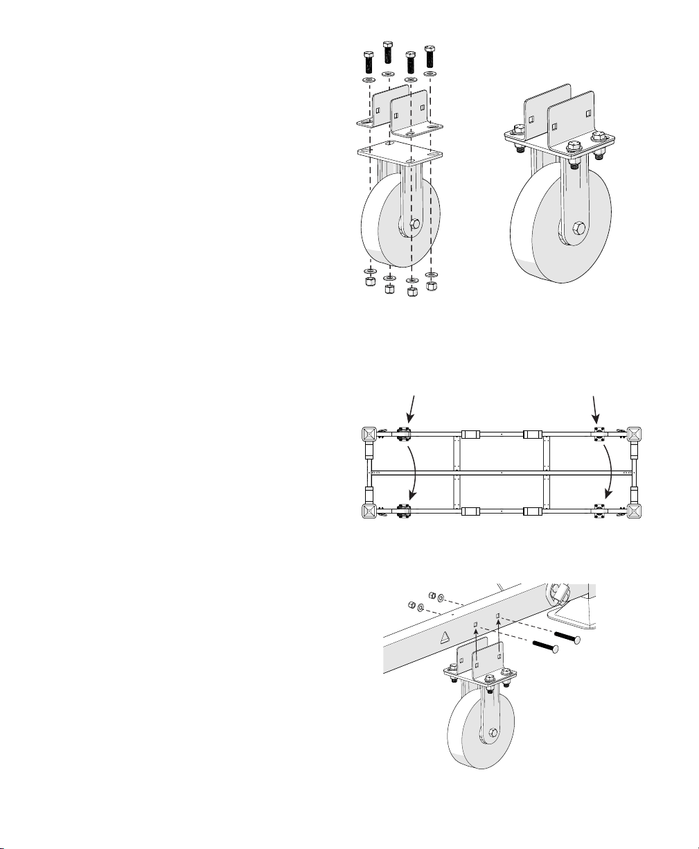
Caster Installation
Caster Bracket Assembly
Loosely install brackets onto
the casters with the nuts, bolts
and washers provided. Follow
assembly shown on the right.
Do not tighten.
Caster to Juggernaut Assembly
Locate the 2 square mounting holes on the
each side near the end of the cart. Align
brackets with the square mounting holes.
Install onto the frame as shown right using
the carriage bolts and nuts provided.
Tighten the carriage bolts and nuts attached
to the frame. Next tighten the 4 nuts and
bolts for the caster/bracket.
Rotating
Caster Wheels
Fixed
Caster Wheels
Caster Wheel Placement
It is recommended to use a forklift and rise the
Juggernaut cart off the ground about two feet.
The Juggernaut Cart is equipped with two sets of
casters, rotating and fixed.
Before assembling the casters to the Juggernaut
make sure the rotating casters are on both
positioned on the same short end of the cart.

TIE DOWN Safety Products Division
800-241-1806 • 404-344-0000 • www.tiedown.com
Page 5 of 8
Quick Set Base
Set Up Instructions
Prior to installation/set-up of the Universal Guardrail System, a competent person must develop a
system layout plan.
1. Evaluate the surface to confirm that the guardrail system will not be installed on top of gravel or
slippery surfaces.
2. Measure the work surface area to be protected and space the Quick SET base plate accordingly
(10 ft. centers for long runs, 7-1/2’ and or 5 ft. centers where required).
3. All Quick Set Base plates must be located a minimum distance of 18 in. from a “no curb”/parapet
leading edge, or opening. If the work location has a curb or parapet edge, the Quick Set Base can be
placed perpendicular against the rise of the structure.
4. Always be aware of all electrical hazards (ELECTRICITY KILLS). A minimum safe distance of 10 ft. away
from power lines and other electrical hazards must be maintained at all times.
5. Quick Set base plates must be oriented correctly with the guardrails installed perpendicular. Toe boards
are installed parallel to the guardrails. Safety clips pins must be inserted through all Quick Set base
plates and guardrails.
6. The guardrail layout must be installed in a continuous run, and must completely block all applicable
leading edges of potential fall hazards. Do not attempt to relocate a fully assembled system.
Continuous Guardrail Run
Leading Edge
Leading Edge
If you have any questions
call 800-241-1806 or 404-344-0000

TIE DOWN Safety Products Division
800-241-1806 • 404-344-0000 • www.tiedown.com
Page 6 of 8
Quick Set Base
Set Up Instructions
Assembly and Mounting
1. Place all Quick Set bases around the leading edge of the fall hazard area, space the Quick Set bases at
approximate lengths of the corresponding length of guardrail (10’, 7.5’ and 5’).
2. When assembling the guardrails into the Quick Set, position the guardrails between the fall hazard and the
installers work area. Position one leg of each guardrail into the outermost Quick Set retaining tube.
Maintaining the guardrail positions between the installers body and the fall hazard edge, position the tube
into the adjacent Quick Set retaining tube.
3. Once each guardrail tube has been inserted into the Quick Set retaining tube, install the retaining pins.
Single Screw Attachment
Must be attached through
the center slot
Multi Screw Attachment
Additional screws may be
added for additional security
Securing the Base
Quick Set base plates are only approved for concrete substrates with a minimum slab thickness of 6 inches with a
minimum concrete strength of 3,000 psi, normal weight, (cracked) concrete.
Screw should be 3.5 inches in length. 0.5 inches in diameter.
Rated for 1000 pounds of pull out force in substrate used.
1. Using the Quick Set plate as a guide: first drill a 1/2”x 4” hole using a carbide-tipped masonry bit. The quickest,
easiest way to drill into concrete is with a hammer drill. It’s also important to blow or vacuum the concrete dust
from the hole before inserting the fastener. Fasteners grip much more tightly to clean, dust-free holes.
2. Follow installation instructions supplied with the type fastener you are using.
6” Min.
4” Deep

TIE DOWN Safety Products Division
800-241-1806 • 404-344-0000 • www.tiedown.com
Page 7 of 8
Instructions
Use these instructions as part of a training program as required by OSHA and any applicable state agency. The
user must understand how to safely use the Universal Guardrails and all safety equipment used in combination
with the Universal Guardrails.
A competent person who is highly trained and experienced, assigned by the employer, must be responsible for
all elements of a fall safety program, including the regulation, management, and application as it relates to the use
of the Universal Guardrails and related system.
Safety Information
Serious injury, bodily harm or death may result if there is a failure to understand and comply with safety
regulations. These instructions are not all-inclusive and are for reference only and not intended to replace a
competent person, knowledge or judgment of Federal and State Standards. New OSHA Rule in affect:
Walking-Working Surfaces, 1910.28, please consult this as well as all local, State and Federal OSHA rules
Workplace conditions including, but not limited to weather conditions, corrosive chemicals, potential electrical
hazards, sharp objects/surface, and slope of the surface must be evaluated by a competent person before equipment
is selected and installed and before work begins. Do Not misuse equipment. Do Not alter equipment. Unprotected
leading edges and sides that are 6 feet or more above the next lowest level require the use of these guardrails,
safety nets or personal fall protection devices. Never lean or climb on a Roof Zone Guardrail.
Inspection of the Universal Guardrail must take place routinely at intervals not to exceed 6 months. A competent
person other than the end user must be responsible for the inspection of the Universal Guardrail System. All
inspection must be recorded by a competent person who must sign their initials and date (month/year) in the
appropriate box on the inspection grid decal for the month and year the inspection was conducted.
Prior to installation/set-up of the Universal Guardrail System, a competent person must develop a system
layout plan.
1. Evaluate the roof surface to confirm that the Guardrail System will not be installed on top of gravel or slippery surfaces.
2. Measure the work surface area to be protected and space the Zip base plate accordingly (10 ft. centers for long
runs, 7-1/2’ and or 5 ft. centers where required).
3. All Zip Base plates must be located a minimum distance of 18 in. from a “no curb”/parapet leading edge, or
opening. If the work location has a curb or parapet edge, the Zip Base can be placed perpendicular against the
rise of the structure.
4. Always be aware of all electrical hazards (ELECTRICITY KILLS). A minimum safe distance of 10 ft. away from
power lines and other electrical hazards must be maintained at all times.
5. Zip base plates must be oriented correctly with the Universal Guardrails installed perpendicular. Toe boards are
installed parallel to the guardrails. Safety clips pins must be inserted through all zip base plates and guardrails.
Universal Guardrail
Fall Protection

www.tiedown.com
ISO 9001:2015 Certification
Intellectual property of TIE DOWN Inc.
©2020 TIE DOWN, Inc.
Instruction #08340(E1733 Rev. 6/22/20)
Safety Products Division
605 Stonehill Drive SW
Atlanta, Georgia 30336
800-241-1806 • 404-344-0000
Guardrail Outrigger
Outrigger
Assembly and Use
1. Place all Zip Rail Baseplate's around the leading edge of the fall hazard area, space the Zip Rail Baseplate's at
approximate lengths of the corresponding length of guardrail (10’, 7.5’ and 5’).
2. When assembling the guardrails into the Zip Rail Baseplate, position the guardrails between the fall hazard and
the installers work area. Position one leg of each guardrail into the outermost Zip Rail Baseplate retaining tube.
Maintaining the guardrail positions between the installers body and the fall hazard edge, position the tube into
the adjacent Zip Rail Baseplate retaining tube.
3. Once each guardrail tube has been inserted into the Zip Rail Baseplate retaining tube, install the retaining pins.
4. Install toe-boards if and whenever required.
Continuous Guardrail Run
Leading Edge
IMPORTANT!
Guardrail Outriggers MUST be used at both ends of any
interruption in continuous guardrail sections, or at both ends
of a continuous guardrail section.
6. The Universal Guardrail System must be installed in a continuous run, and must completely block all applicable
leading edges of potential fall hazards. Do not attempt to relocate a fully assembled system.
7. Guardrail Outriggers MUST be used at both ends of any interruption in continuous guardrail sections, or at both
ends of a continuous guardrail section. See back for example.
8. A Guardrail Outrigger is installed perpendicular to a continuous guardrail run.
IMPORTANT: Zip Base plate must be placed perpendicular to the orientation of the guardrails. The base
can be orientated with long or short edge pointed to the direction of the leading edge. To minimize trip
hazards, install short end of base away from leading edge.
Table of contents
Other TIE DOWN Safety Equipment manuals

TIE DOWN
TIE DOWN 70853 User manual

TIE DOWN
TIE DOWN 70910 Quick start guide

TIE DOWN
TIE DOWN 70818 User manual

TIE DOWN
TIE DOWN 14367 Quick start guide

TIE DOWN
TIE DOWN PENETRATOR User manual

TIE DOWN
TIE DOWN Hippo Anchor 65219 User manual

TIE DOWN
TIE DOWN Parapet Anchor User manual

TIE DOWN
TIE DOWN 72874 User manual

TIE DOWN
TIE DOWN Big Foot 60060US Guide
Popular Safety Equipment manuals by other brands

TEUFELBERGER
TEUFELBERGER GRANIT PRO Manufacturer's information and instructions for use

Janus
Janus 3M Novec 1230 Refill Manual

SICK
SICK ReLy OSSD2 operating instructions

Larson Electronics
Larson Electronics EXP-RSP-FKWL-WLS-V1 manual

GARDEO PRO
GARDEO PRO GPROTECT-6 Original instructions

IRUDEK
IRUDEK OREKA manual


