Star Headlight & Lantern DLXT-121 Series User manual
DLXT
Thinline Auxiliary LED Lights
PLIT424 REV. F 4/10/13
DL T-121*** or DL T-241***
(12 VDC)
(24 VDC)
DL T-124*** or DL T-244***
(12 VDC)
(24 VDC)
Phase 1
Flash Pattern #
Phase 2
Flash Pattern #
Pattern Type
Pattern Description
Shortcut
1 11 A Fast Singleflash (1.9 CPS)
Pattern 1
(Phase 1)
:
3 sec or 1 flash
Pattern 11
(Phase 2)
:
9 sec or 3 flashes
2 12 B Flicker flash (1.7 CPS)
3 13 C Post pop (1.4 CPS)
4 14 PSU-flicker (0.4 CPS)
5 15 E
Random (1.9 CPS)
(DEFAULT PATTERN)
6 16 F Quadflash (1.0 CPS)
Pattern 6
(Phase 1)
:
6 Sec or 2 flash
Pattern 16
(Phase 2)
:
12 sec or 4 flashes
7 17 G Quadflash
w/Post-Pop (1.0
CPS)
8 18 H Singleflash (1.0 CPS)
9 19 I oubleflash (1.0 CPS)
10 20 J elta-Omega (0.3 CPS)
N/A Steady
(see below)
18 sec or 6 flashes
Pattern Shortcuts: Hold Green wire to ground for indicated
time.
Steady Burn: Not in pattern cycle. Only accessible through
shortcut. Hold Green wire to ground for 1
seconds (light will flash 6 times).
You can synchronize up to six
lights with compatibility.
DO NOT CONNECT WH TE W RES
UNT L PROGRAMM NG HAS BEEN
COMPLETED FOR ALL L GHTS!!
1. Power up the first unit and select a
Phase 1 pattern. Touch and
release the green wire to ground to
change patterns.
2. Program the second light with
the same Pattern Type.
Lights with the SAME phase
flash together (simultaneous).
Lights with DIFFERENT phases
flash opposite one another
(alternate).
3. After programming all lights, tie
off the green wires and connect
the white wires together.
4. Test lights by applying power to all of them at the same time.
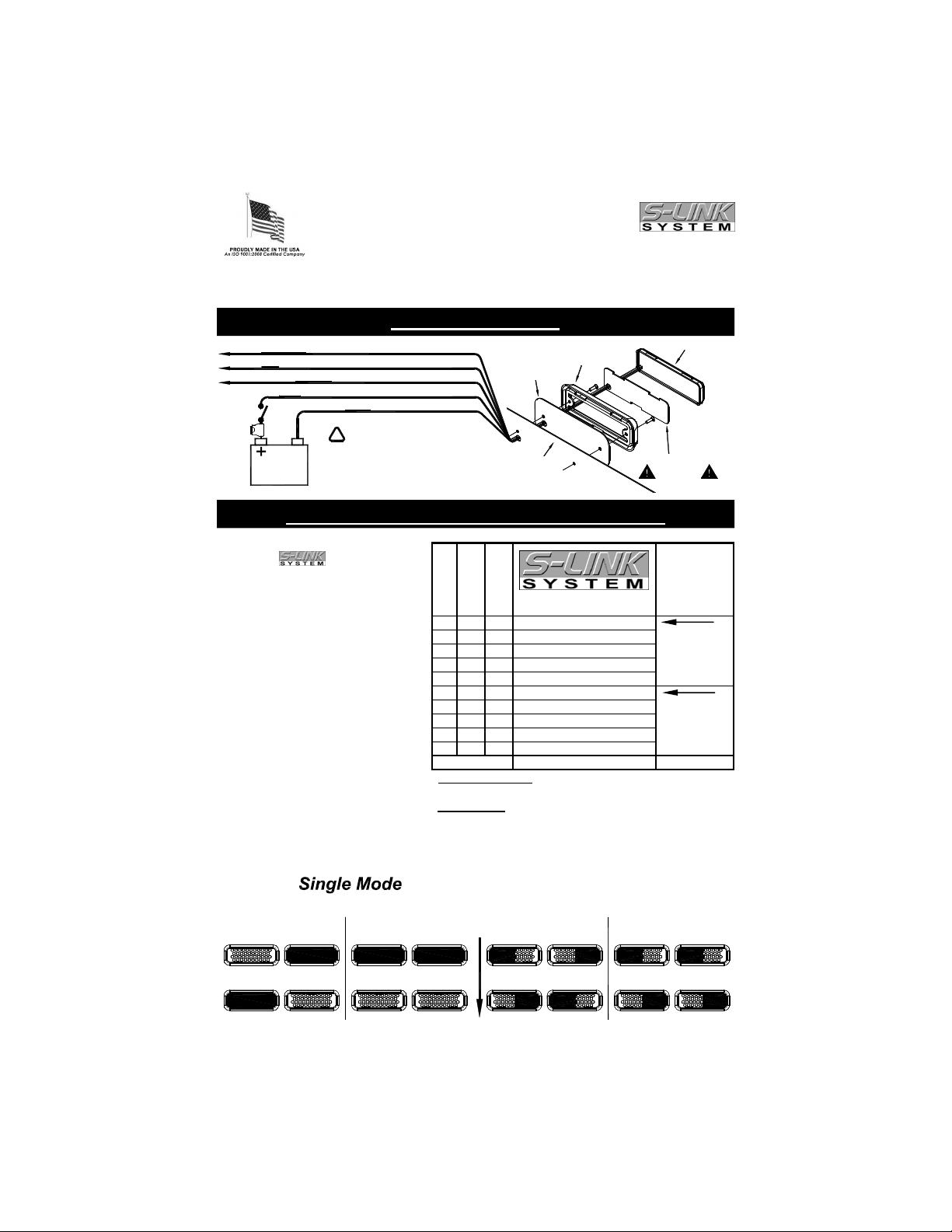
Quick nstall Guide
Warning
Lights
ON/OFF
Switch
-
Bezel
Ground: Connect to negative terminal of battery
BLACK
Mounting Surface
Rubber
Mounting
Gasket
IMPORTANT
Foam Compression Gasket
LED Array
GREEN
WHITE
GREEN w/WHITE
Sync: Attach to White wires from other S-Link Lights for synchronization
Split/Single: Connect with Black to Ground for Single Mode
Connect with Red to Switched Power for Split Mode
5 AMP
FUSE
RED
Power: Connect to switched power
12VDC or 24VDC
(depends upon model)
BATTERY
Use minimum
1 AWG wire
!
Pattern Select: Touch and release to ground to program
Pattern Programming and Synchronization
Light 1 Light 2
(OFF)(ON)
Simultaneous Pattern
(Programmed for same Phase)
Light 1 Light 2
Alternating Pattern
(Programmed for opposite Phases)
TIME
Split Mode
Light 1
Back & Forth Pattern
(Programmed for same Phase)
n/Out Pattern
(Programmed for opposite Phases)
(OFF) (ON)
Light 1 Light 2 Light 2

-2-
The installer must have a firm knowledge of basic electricity, vehicle electrical systems,
and emergency equipment.
If you need to drill any holes when installing this light, please take care to check that
BOTH SIDES of your drilling surface are clear from obstructions, to ensure that you do
not damage your vehicle and or pre-existing wiring.
Choose a mounting location away from any air bag deployment areas.
Controls should be placed within convenient reach of the driver.
Use only soap and water when cleaning this product. Use of other chemicals may
discolor the lens and/or housing, thus diminishing the output of the light. Lenses that
have become discolored should be replaced immediately!
DO NOT use a pressure washer to clean this light. Use of a pressure washer may
damage the light and WILL VOID THE WARRANTY.
nstallation Notes
Wiring Notes
When wiring your lights, it is recommended that you take the following
precautions to reduce any Electromagnetic Interference (EMI).
Keep LED modules and any radios as far away from each other as possible.
Separate the radio wires and the LED wires.
Any excess wires should be cut short.
The Ground, Power, and Synchronization wires should be bound tightly together as
they run from light to light, through your switchbox, and finally to the battery.
Do not ground each unit independently to the chassis. Run the ground for each unit
in a “bus” like structure, to the negative terminal on the battery.
Steady Burn Programming
Programming Steady urn Pattern in Single Mode:
1. Power the light up - Red wire to power
Black wire and Green/White wire to Ground.
2. Hold Green wire to Ground until the light blinks six times (approximately 1 seconds),
then release it. The light should change to the Steady Burn pattern.
3. To exit Steady Burn pattern: Touch and release the Green wire to Ground.
Programming Steady urn Pattern in Split Mode:
1. Power the light up (both Red and Green/White wire to power). Touch and hold the
Green wire to Ground until the light blinks six times (approximately 1 seconds), then
release it. One of the two halves will become steady, while the other flashes.
2. To change the pattern on the flashing side, touch and release the Green wire to Ground.
3. To flip-flop the steady side and the flashing sides, hold the Green wire to Ground until
the light flashes 5 times (approximately 15 seconds) and then release it.
4. To exit Steady Burn pattern: Touch and release the Green wire to Ground.
Power MUST be applied to all synchronized lights
simultaneously. Excessive switch bounce or attempting to
power the units up independently will result in erratic operation.
-3-
Please Note: These instructions are provided as a general guideline only. Some
vehicles may require special mounting, wiring, and/or weather-sealing. This is the
sole responsibility of the installer. Star Headlight & Lantern Co., Inc. assumes no
responsibility for the integrity of the installation for this or any of its products.
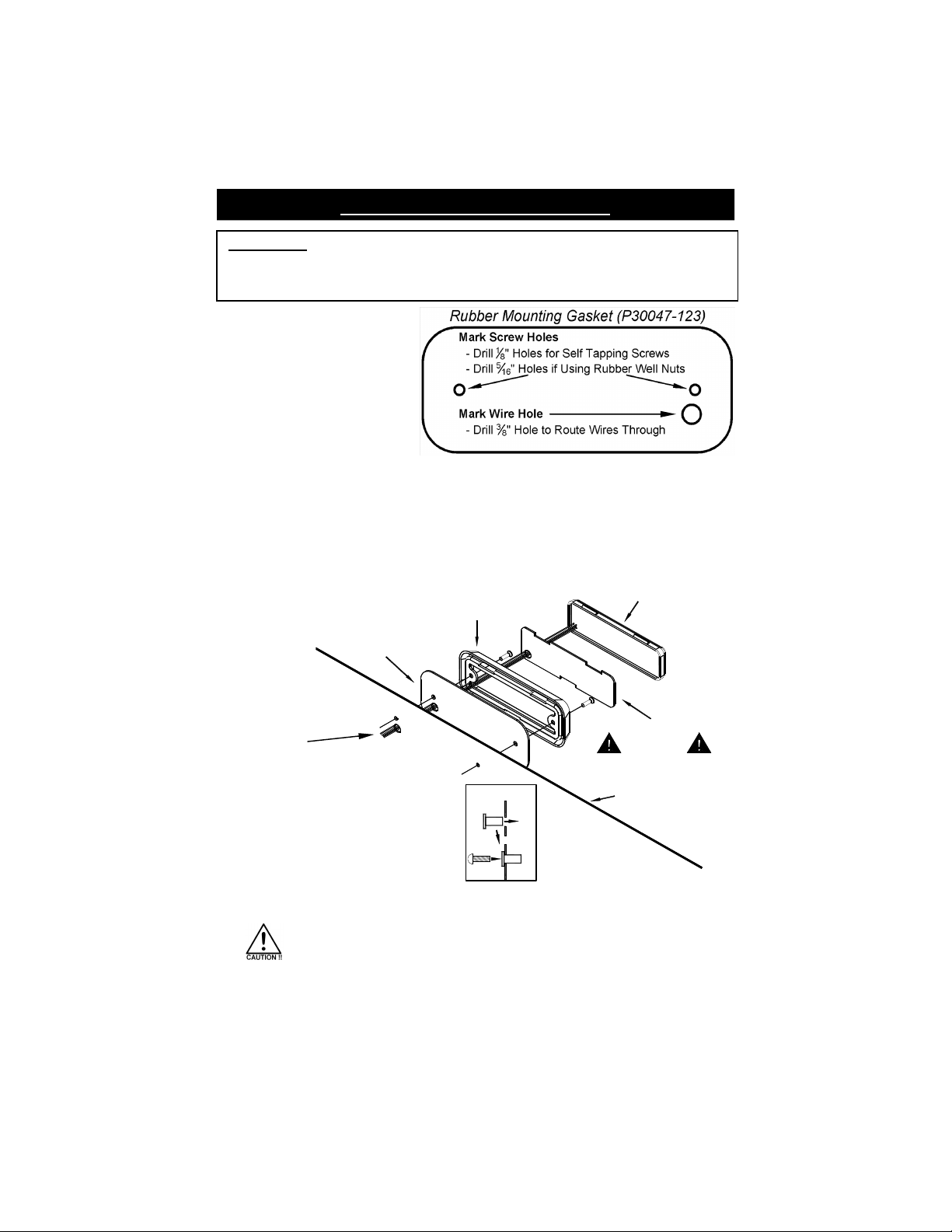
Surface Mounting nstructions
Rubber Mounting Gasket
Bezel
Foam Compression Gasket
LED Array
Mounting Surface
IMPORTANT
3. Route the wires as
shown to the right:
4. Seal the wire hole with
silicone to prevent your
wires from becoming
damaged.
5. If you are using the well nuts, push the
enclosed rubber well nuts through the
holes until the bottom side of the wider
lip rests on the surface of the vehicle.
6. Review the mounting diagram and use the appropriate screws to mount the bezel.
Check the gasket to ensure it is resting flat and that there are no gaps
between the light and the mounting surface.
Take extreme caution not to over tighten the screws!!! Over tightening
of the screws can strip the holes and result in a faulty mount.
7. Once the bezel is firmly attached to the mounting surface, seat the foam compression
gasket inside of it. Carefully feed any loose wire into the wire hole and press the LED
head into the bezel.
1. Use the gasket as a template
to mark your mounting holes.
2. Determine whether you are going to use the self-tapping screws or the machine screws
and well nuts..
Use the self tapping screws for applications where the mounting surface is a minimum
of .060” (1/16”) thick and is composed of a material that will provide sufficient “bite” for
the self tapping screw.
Use the machine screws and well nuts if your surface is less than .060” thick and/or
composed of a material insufficient for securing with self tapping screws.
WELL NUT
INSTALLATION
-4-
If you have any questions concerning this or any other product,
please contact our Customer Service Department at (5 5) 226-97 7.
If a product must be returned for any reason, please contact our Customer Service Department to
obtain a Returned Material Authorization number (RMA #) before you ship the product back.
Please write the RMA # clearly on the package near the mailing label.
LED FIVE YEAR LIMITED WARRANTY
The manufacturer warrants this LE light against factory defects in material and workmanship for five years
after the date of purchase. The owner will be responsible for returning to the Service Center any defective
item(s) with the transportation costs prepaid. The manufacturer will, without charge, repair or replace at its
option, products, or part(s), which its inspection determines to be defective. Repaired or replacement
item(s) will be returned to the purchaser with transportation costs prepaid from the service point. A copy of
the purchaser's receipt must be returned with the defective item(s) in order to qualify for the warranty
coverage. Exclusions from this warranty include, but are not limited to, domes, and/or the finish. This
warranty shall not apply to any light, which has been altered, such that in the manufacturer's judgment, the
performance or reliability has been affected, or if any damage has resulted from abnormal use or service.
There are no warranties expressed or implied (including any warranty of merchantability or fitness), which
extend this warranty period. The loss of use of the product, loss of time, inconvenience, commercial loss or
consequential damages, including costs of any labor, are not covered. The manufacturer reserves the right
to change the design of the product without assuming any obligation to modify any product previously
manufactured.
This warranty gives you specific legal rights. You might also have additional rights that may vary from state to
state. Some states do not allow limitations on how long an implied warranty lasts. Some states do not allow
the exclusion or limitation of incidental or consequential damages. Therefore, the above limitation(s) or
exclusion(s) may not apply to you.
NOTICE
Due to continuous product improvements, we must reserve the right to change any specifications and
information, contained in this manual at any time without notice. Star Headlight & antern Co., Inc. makes no
warranty of any kind with regard to this manual, including, but not limited to, the implied warranties of
merchantability and fitness for a particular purpose. Star Headlight & antern Co., Inc. shall not be liable for
errors contained herein or for incidental or consequential damages in connection with the furnishing,
performance, or use of this manual.
mportant
: This product is used to warn traffic. Improper use may result in
vehicular collision, personal injury and/or death. Star Headlight & Lantern Co.,
Inc., and its subsidiaries shall not be held responsible for damages directly or
indirectly caused by improper use of this product.
This manual suits for next models
3
Table of contents
Popular Light Fixture manuals by other brands


Lightolier
Lightolier TRADITIONAL STYLE RADIANCE Pendants Instructions for installation

Energetic Lighting
Energetic Lighting E1STA Series installation instructions
American DJ
American DJ Mega Pixel Arch User instructions

Cooper Lighting
Cooper Lighting F-Bay I8 Series Specifications

Cooper Lighting
Cooper Lighting RD Series Specifications

Philips
Philips FBP90 specification