Star Meter CYYZ61 User manual

An instruction manual
CYYZ61 Hygienic pressure transmitter
星仪传感器
STAR METER
4. Product Features
a) Using diaphragm isolation technology
b) Integrated chip, wide range of supplied voltage
c) Easy to clean up,Compact structure, easy installation
d) Frequency cutoff design, strong anti-interference ability,
lightning protection
e) Current limiting, voltage limiting, reverse connection
protection(limiting current output)
f) High accuracy, good stability, fast response
5.Technical parameters
Measuring media : Liquid or gas(compatible with contact media)
Overall material: Diaphragm 316L stainless(contacted)
Process connection 316L stainless(contacted)
Casing 316L stainless
Display case ABS engineering plastic(digital tube display)
Hessman connector ABS engineering plastic
Pressure range: 0~10kPa~4MPa (read the range selection form
for details)
P r e s s u r e m o d e : Gauge pressure
Output signal: 4~20mA、RS485 (Standard Modbus-RTU protocol),
(0~10VDC、0~5VDC、1~5VDC、0.5~2.5VDC customized)
Supply voltage: 12~36VDC Normal
15~36VDC Normal(with display or output 0~10VDC)
3~5VDC Customized (Output 0.5~2.5VDC/RS485)
Accuracy class: 0.1%FS (range≥100kPa customized)
0.25%FS(range≥100kPa customized)
0.5%FS (10kPa≤range<100kPa default)
Device display accuracy class of 0.5, shown by (LED) digital tube
Working conditions: contact media temperature -40~130℃
Ambient temperature-40~85℃
Ambient humidity 0%~95%RH(no condensation,no condensing)
Temperature compensation: -10-70 ℃ (accuracy of 0.25% FS, 0.5% FS, 1% FS)
-40-80 ℃ (accuracy of 0.1% FS)
Seismic performance : 10g(20...2000Hz)
Overload capacity: 200% full scale or 120MPa(minimum value)
Response frequency: analog signal output≤500Hz, digital signal output ≤5Hz
Stability : ±0.1% FS/year
Temperature drift: ±0.01%FS/℃(within the temperature compensate range)
Overall weight : no display ≈190g display ≈270g
Protection lever: IP65(no display)IP54(display)
Note: The above protection level refers to the level
achieved after the electrical connection is complete.
Power range : Current type≤0.02Us(W)
Digital type≤0.015Us(W)
Voltage type≤0.008Us(W)
Voltage type(output 0.5~2.5)≤0.001Us(W)
Note:Us=Supplied voltage
Load characteristics : Current type load ≤{(Us-7.5)÷0.02(Us=supply
voltage)}Ω voltae type load ≥100kΩ
6.Dimensions
Figure 6-3 display clamp interface
Figure 6-4 display Threaded interface
6mm
60mm
φ
27mm
φ50.5mm
100mm
48mm
145mm
SENSORS
48mm
6mm
φ50.5mm
PG9
PG9
PG9
PG9
! Note: The total length of the digital signal output
is increased by 33mm.
Figure 6-1 no display Clamp interface
Figure 6-2 no display Threaded interface
Note 2: The marked place can be rotated 360°
medical technology
Pharmaceutical industry
Food and beverage industry
Typical application
76mm
12mm
116mm
φ
27mm
S=27
SENSORS
S=27
12mm
48mm
48mm
76mm
φ
27mm
161mm
version number20.4.23
1.Overview
1.1 Safety guidance
This operational manual contains important information on how to use the
transmitter correctly. The installation personnel of the transmitter should
read this manual carefully before operation. In case of further explanation
or special questions, which cannot be addressed in this manual, please
contact our company for assistance on necessary information.
Please pay attention to the warning signs on the manual! Do not use
crystallized or solidified measure medium, to avoid damaging of the sensor.
The operator must strictly follow the safety instructions and user’s
manual during operation. Furthermore, the operator should comply with the
occupational safety rules, the accident prevention guidelines, the national
standards and engineering specifications as well.
Please keep this manual in a safe place near the transmitter for easy
access.
The copyright of this operational manual is protected. This version of
operational manual was edited according to the functions of corresponding
products, the product functions and operation procedures are described as
complete as possible. If there is any error, please don’t hesitate to
contact us. The company is not responsible, in regard of any fault
description or its possible consequences.
–The right to modify the technical parameters is retained–
1.2 Icon description
Danger! - Hazard that may result in death or serious injury.
Warning!- Potential hazard that may result in death orserious injury.
Cautious!-Potential hazard that may cause minor injury.
Reminder!-Potential hazard that may result in personal injury.
Tips!-Tips and information for smooth operation of the equipment.
1.3 Manual user
Warning! This manual is suitable for technicians.
1.4 Limit of liability
The company will not be held responsible nor provide any warranty
service, in case of transmitter damages caused by failure to follow the
instruction manual, inappropriate use, self-modification or destruction.
1.5 Instructions for use
CThe pressure transmitter CYZ61 series is suitable for pressure
measurement in liquid or gas and process industries. Operators are
responsible for checking whether the equipment is suitable for operating
conditions. If you have any questions, please contact our sales department
to ensure the correct application of the transmitter. The Company shall not
bear any responsibility for the influence caused by improper selection.
The purchased model is suitable for certain gas or liquid medium as
described in the measurement samples. The user must ensure the
compatibility of contact media and transmitter.
Warning!
Inappropriate use may lead to danger!
2.Product overview
CYYZ61 series pressure transmitters adopt OEM pressure sensor with
stainless steel diaphragm as signal measuring element. After automatic
testing by computer, temperature compensation of zero point and sensitivity
in wide temperature range is carried out by laser resistance adjustment
technology. The amplification circuit is located in the stainless steel
case, which converts the sensor signal into standard output signal, giving
full play to the technical advantages of the sensor, so that the CYZ61
series pressure transmitter has excellent performance. It is easy to clean,
anti-interference, small temperature drift, high stability, and has high
measurement accuracy. It is an ideal pressure measuring instrument in
pharmaceutical, food and other industries.
3.Working principle
The pressure sensors diffuses a wheatstone electric bridge on
mono-crystalline silicon, and stressed by the measuring media (liquid or
gas)to cause change of the bridge wall resistance value(piezoresistive
effect). In result, a differential voltage signal will be generated, which
converts the signal corresponding to the range into standard analog
signal(as shown in Figure 3-1)or digital signal.
!
!
!
!
!
!
Figure 3-1
Pressure
source Sensor
Signal
processing
circuit
Output
analog
quantity
or
digital
signal
Customer
collecting
device
1200
1000
800
600
400
200
107.5 15 20 Working volt
25 30 36
RL(Ω)
Loading resisitance (4~20)mA DC
Us(VDC)
Working zone
Figure5-1
Note1: The total length of the digital signal output
is increased by 33mm.
7.Installation and precautions
Warning!
a)Installed without pressure nor power supply.
Warning!
b)Transmitter should be installed by technician who read and
understood this operational manual.
Danger!
c)The transmitter uses diffused silicon oil-filled core, which may
cause explosions if in-properly handled. Do not measure oxygen for sake
of he safety.
Danger!
d) This product is not explosion-proof, using in explosive area may
cause serious injury and significant loss.
Warning!
e) It is prohibited to measure media that is not compatible with
the transmitter.
f) Please check if the package is in good order when receiving
the product, confirm the transmitter model and specifications.
!g) To avoid the damage of diaphragm, please unpack the package
and protective cap before starting the equipment. Please keep the
protective cap of the product. When the equipment is dismantled,
please put on a protective cap for the pressure interface immediately.
Be extra careful when handling unprotected diaphragms, because
unprotected diaphragms are very sensitive and easily damaged.
!h)Handle with care, do not throw, do not force during
installation of transmitter.
i)Vertical installation is applicable when pressure is below
0.03MPa (except for gas),to avoid affecting themeasurement accuracy.
Others can be installed at any angle. In case the interface size does not
match, it is allowed to make connecting adaptor.
j)During installation, attention should be paid to the upward
installation of the pressure interface of the equipment (for gas
emission).
k)If the pressure interface is upward or lateral when the
transmitter is installed, it is necessary to ensure that there is no
liquid flowing in the equipment shell, otherwise moisture and dirt
will block the air outlet near the electrical connection, or even
cause equipment failure. It is necessary to ensure that there is no
dust and dirt residue on the edge of threaded connection of electrical
connection.
l)It is recommended to install at minor temperature gradient variations zone.
m)It is recommended to adopt lightning protection and over
voltage protection facility between power distribution box or power
supply and the transmitter, for the fact that there will be danger if
the transmitter is installed in a harsh area.
n)While measuring high temperature media, please ensure the
media temperature is not higher than the maximum work temperature of
transmitter. If necessary, it is required to install a cooling device.
o)Install a pressure cutoff valve between the transmitter and
media, to inspect and avoid interference with measurement accuracy
caused by pressure port clogging.
p)During the installation, use a wrench to tighten the transmitter
from the hexagonal nut at the bottom, to avoid wire disconnection caused
by direct rotation of the upper part of the device.
!q) This product is a light current device, it must be laid
separately from high current cables during wiring, and comply with
relevant national wiring standard (GB/T50312-2016).
!
!
!
!
!
STAR METER
24-hour service hotline:400-600-4496 Executive standard JB∕T 10726-2007www.star-sensor.com
1

9.Specification selection
▲0~20 kPa
0~0.4MPa
0~1.6MPa
05
09
13
06
10
14
0~100kPa
07
▲ accuracy level 0.5; no mark accuracy level default 0.25, level 0.1 can be customized.
67 Custom
04 ▲0~10kPa ▲0~50kPa
08 0~200kPa 0~0.5MPa 11 0~0.6MPa
12 0~2.5MPa 15 0~4MPa
0~1MPa
Range Selection Schedule
Code Range Code Range Code Range Code Range
CYYZ61 Hygienic pressure transmitter selection table
CYYZ
Clamp(50.5)
35
61 H12 A1 14 B G
For example: CYZ61-H-12-A1-14-B-G (Hygienic Pressure Transmitter, Hessman Lead (No Display),
Range 0-1 MPa, Output 4-20 mA, Connection M20*1.5, Accuracy 0.25, Power Supply 12-36 VDC).
Note 1: The output is 0.5-2.5 VDC/RS485, which can not be displayed.
61
H
X
CYYZ
Pressure transmitter
Transmitter type
Code
Hygiene type (default no connection)
With or without display
Code
Without display (Hausman lead)
Display (Hausman lead)
Range
Code
See range selection table attached
Signal output
4-20mA Two-wire systme
RS485 communication interface
(standard M odbus-RTU protocol) four-wire system
Custom
Code
A1
RS
DZ
Custom
M20*1.5 External thread
G1/2 External thread
44
14
19
Accuracy level
0.1%FS Customization (range ≥100KPa)
0.25%FS Regular (range ≥100KPa)
0.5%FS Regular ( range <100kPa)
Code
S
B
C
Supply voltage
12-36VDC Regular
15-36VDC
Regular (with display or output 0~10VDC)
3-5VDC Custom (Note 1)
Custom
Code
G
G2
G3
DZ
Custom
Other custom requirements
Regular
Code
D
No
Example of selection
Connection type
Code
version number20.4.23
8.wiring installation
c)Remove wire holder from dismantle notch with flat screw driver.
d)Lay shielded cable through the wire hole as figure8-3 after removing,
connect wire at the terminal behind the wire holder as instructed in the
figure, restore and screw the wire holding cap tightly.
After wiring is completed, the wire outgoing direction can be changed by
the direction of wire holder
It is required to ensure the outer diameter of the cable used is within
the allowable range of the guard staple. And the cable must be fitted in the
guard staple firmly and without clearance. The diameter of wire holding cap
is 4~6mm.
The plug must be correctly and properly installed to ensure the protection level.
Wire holding cap
Figure 8-3
VDE
lift 1
3
2
GDM
+S
10A
250V
~
Dismantle notch
Plug case Wire holder
Wire hole
Figure8-1 Figure8-2
b)Remove plastic plug units indicated
in the figure above.
a)Unscrew the star type M3 screw
Plastic pug unit
8.1 Wiring
Pull out the terminal block which is inside the casing of plug to
connect the wire, wiring steps areas shown in the following figure.
r) Ensure that the power supply voltage meets the requirement
of the transmitter. And make sure the maximum voltage of the pressure
source is within the range of the transmitter.
s)Increase pressure and reduce pressure very slowly during the
pressure measurement, to avoid instantaneous high voltage or low
voltage.
Warning!
t) Make sure the pressure source and power are disconnected
before disassembling the transmitter, to avoid accidents in result of
media ejection.
u) Do not disassemble during usage, and do not touch the diaphragm,
!
8.2 Wiring diagram
Voltage output wiring figure 8-5 (three-wire system)
Current output wiring diagram 8-4 (two-wire system)
P
Transmitter
Blue line(V-)
Red line(V+)
Collecting device
Power supply(VDC)
Pressure input
U
+ -
A
P
Transmitter
Red line(V+)
Blue line(V-)
Yellow line(OUT)
Pressure input
V
U
+ -
Collecting device
Power supply(VDC)
3
2
1
1、Positive power supply(V+)
2、Positive output (OUT)
3、Negative power supply(V-)
、Earthing
3
2
1
1、Positive power supply(V+)
2、Negative power supply(V-)
、Earthing
Representing the shielded wire, all marked grounding points
must be effectively grounded.
The transmitter casing defaults to be ground, all field devices
are required to be effectively grounded.
Only the current output has reverse connection protection
(no damage but does not work), current limiting and voltage limiting
protection. Reversed connection of all other output signals can cause
damage to the transmitter.
1、Positive power supply(V+)
2、RS485A(A)
3、Negative power supply(V-)
、RS485B(B)
3
2
1
RS485 (digital signal) 8-6 output wiring diagram (four-wire system)
P
Transmitter
Red line(V+)
Blue line(V-)
Yellow line(A)
White line(B)
PC
device
U
+ -
Pressure input
Collecting device
Power supply(VDC)
10.Protocol Description
(limited to RS485 signal output 485 all product addresses default to 01)
10.2.Modbus-RTU Read Data 03 Command Description(Data is hexadecimal)
10.1.Basic technical parameters of the transmitter
(This protocol complies with the Modbus communication protocol, and uses a subset
of the Modbus protocol which is RTU mode. RS485 half-duplex working mode)
a)Output signal: RS485 (Maximum distance can be up to 1000 meters. Maximum connection 32 channels)
b)Standard Modbus-RTU protocol
(03 function reads data, 06 function inputs setting data)
c)Data format: 9600, N, 8, 1 (9600bps, no parity, 8 data bits, 1 stop)
d)Measurement range: 0-X (MPa, kPa....)
e)Resolution: 0.05%
f)Output data: 0...2000 (other range customize)
g)Response frequency: ≤ 5Hz
h)Response speed: ≥10ms
Protocol format description
Host command
Return from
machine
Device address
Device address
Address
Address
Data address
00 00
02*CN
Data byte
Function code
Function code
03
03
Number of read data
CN
Sensor data
S_HN ,S_LN
16CRC code(low before high after)
16CRC code(low before high after)
CRC0 CRC1
CRC0 CRC1
Communication example(reading a sensor signal):
The sensor communication device address of 0-1.6 MPa is set to 01, ie
[Address]=01 (Address range 01-254);
And, CRC0=84, CRC1=0a. Then send and return data should be as follows:
Send: 01 03 00 00 00 01 84 0A
Back: 01 03 02 02 AC B9 59
02AC is hexadecimal, converted to decimal 684;
Data output: 0-2000 corresponds to 0-1.6 MPa, so the current pressure is
P=1.6*684/2000=0.5472MPa
Calculation formula: (range upper limit - range lower limit) ÷ 2000 *
current data + range lower limit = current pressure value
Query example(read the current device address, only to be completed
independently by a single sensor)
Send:FF 03 00 0F 00 01 A1 D7
Back:FF 03 02 00 01 50 50
Then: the address of this device is 01 (hexadecimal)
Example of modification
For example, change 01 address to 09 address:
Send 01 06 00 0F 00 09 79 CF
Retun 01 06 00 0F 00 09 79 CF
Then the original address 01 is modified to 09 successfully, and the
modification of address can be done offline or online. It can work
directly without re-powering at completion.
10.3. Modbus-RTU input 06 command detailed description
(data is hexadecimal)
Protocol format description
Host command
Return from
machine
Device address
Device address
Address
Address
Data address
Data address
00 0F
00 0F
Function code
Function code
06
06
New address
New address
H L
H L
16CRC code (low before high after)
16CRC code (low before high after)
CRC0 CRC1
CRC0 CRC1
10.5. 16CRC verify
The 16CRC verification is a standard error check method used by the
Modbus protocol. Generally, it has detailed descriptions and procedures,
which is not explained here.
10.4.Precautions for use
a)Single RS485 bus must adopt a “hand-to-hand” bus structure. Do
not use a star connection or a fork connection. The address code is set
from near to far, that is, the management computer is connected to the
No. 1 controller, No. 2 is connected to No. 1, No. 3 is connected to No.
2, and so on...
Warning!
b)The AC power supply and the case of the equipment must be grounded
properly and well. There are many places where there are triangular sockets
which in fact, have no grounding at all. Be alerted. When the grounded
properly, the equipment to release the energy by combining with the
lightning protection design when struck by the lightning surge and the
static electricity, to protect the RS485 bus equipment and related chips
from damage. Do not use the RS485 bus if there is no grounding or not
properly grounded, to avoid equipment burnout and casualties.
c)Wire must use multi-strand shielded twisted pair cable with diameter of
more than 0.3 mm2 (multiple strands are for spare). Use PVC pipe separately to
avoid lining with strong current to avoid interference from strong current.
d)485 (A) and 485 (B) must be twisted together, because 485
communication uses differential mode communication principle, and twisted
pair anti-interference performance is good. It is wrong not to use twisted
pairs, and other types of cables.
e)Connect the RS485 converter and the reference ground GND (power
supply negative) of all access controllers, and use the remaining one or all
of the multiple twisted pair cables for the series GND; if the reference
ground is not connected, it will also affect the communication time.
Nowhere, high frequency radiation, mainly from distributed capacitance and
inductance, produces a common mode effect.
f)The shield of the network communication line is grounded. It is
required for grounding, otherwise the potentially danger of the bus is
unknown.
g)If multiple machines or cables are too long for communication, add
120 ohm matching resistors between 485 (A) and 485 (B) at the head and end
of the 485 bus, to improve the communication performance quality. (Must be
pair twisted)
h) The transmission rate, number of load nodes and transmission
distance should be reasonably arranged, to achieve remote low-node for
low-speed, short distance multi-node for high-speed principle.
i)The data communication shall be verified to protect the transmission
accuracy. Generally, the Modbus-RTU is verified by the crc-16 verification
mode, and the error rate is less than 1/1billion.
j)If necessary, choose the company's isolated type model 485, the price
is generally higher.
!
STAR METER
24-hour service hotline:400-600-4496 Executive standard JB∕T 10726-2007www.star-sensor.com
2
version number20.4.23
Warning!
a)Before starting, it is a must to check if the transmitter is
installed correctly, and if there is any obvious damage.
Warning!
b)The transmitter must be operated by professional technicians who
read and understood this operating manual.
Warning!
c)The transmitter is only suitable for working conditions that
meet the technical requirements!
11.Initial start
12.After sales service
a)The company is responsible for all the maintenance costs during
the warranty period, after inspected by the technician of the company and
confirmed there is quality failure.
Warning!
b)Please clean the residual media before returning, especially
substances that is harmful to human health, such as corrosive, toxic,
carcinogenic or radioactive substances;
c)Please keep the warranty card and certificate in a safe place,
and return with the product when there is need of repairing;
d)If there is any faulty with the transmitter, please contact our
after-sales service. If you need to send the transmitter back to the
company for repair after confirming the problem. Please attach the
following information:
Description of the site environment;
Fault phenomenon;
Delivery address and contact information;
!
!
!
!
If the fault phenomenon does not fall within the above range, please
contact our after-sales.
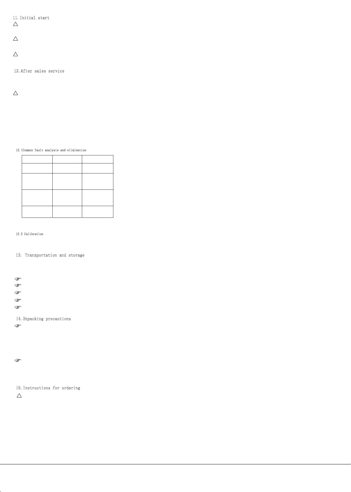
Fault phenomenon
·The transmitter
has no output signal.
·Output irregular jumps
whenthe pressure is constant
·The corresponding output
value is incorrect when
transmitter is not connected
to pressure media
·The transmitter output does
not match with the measured
pressure
·The supply voltage is
incorrect
·The external load is too large
·Whether it is within the
power supply range
·Adjust the external load
·The transmitter is not
operating in required
environment
·Move the transmitter to
the specified environment
or take action to ensure
that the environment meets
the requirements
·The transmitteris not
grounded
·Strong RF interference on
site
·No shielded cable applied
·Use shielded cable and
ground the shield
·The transmitter is
properly connected
to the earth
·The transmitter
is not powered.
·Fault connection.
·Supply power to transmitter
correctly according to
the wiring diagram.
Cause analysis Elimination method
12.1Common fault analysis and elimination
12.2 Calibration
13. Transportation and storage
The transmitter should be kept in a sturdy cardboard box (large device
requires a wooden box), free move in the box is not allowed,be careful when
handling, do not handle with roughly. Store area .
should meet the following conditions:
Zero and full-scale drift may occur during the use of the transmitter.
If the above phenomenon occurs after long time use,it is recommended to send
the transmitter back to us for calibration to ensure high accuracy.
a) Protect from rain and moisture.
b) Free from mechanical shock or shock.
c) Temperature range -20 ~ 55 °C.
d) The relative humidity is not more than 80%.
e) No corrosive gas in the environment.
a) After unpacking, check the packing list to confirm if the documents
and accessories are complete.
The packed documents are:
A copy of the instruction manual.
A product certificate.
A warranty card.
b) Observe if there is any damage caused during transportation, for
proper following up.
c) We hope that the user can safely keep the “warranty card”, please
don’t misplace it, otherwise you can’t return to the factory for free repair!
Warning!
When purchasing the pressure transmitter, the user should select the appropriate
model to make sure it meets specifications of the contact media ,such as the
pressure , temperature , protection level and environmental conditions
14.Unpacking precautions
15.Instructions for ordering
!
STAR METER
24-hour service hotline:400-600-4496 Executive standard JB∕T 10726-2007www.star-sensor.com
3
Other Star Meter Transmitter manuals


