manuals.online logo
Brands
  1. Home
  2. •
  3. Brands
  4. •
  5. Star Micronics
  6. •
  7. Computer Hardware
  8. •
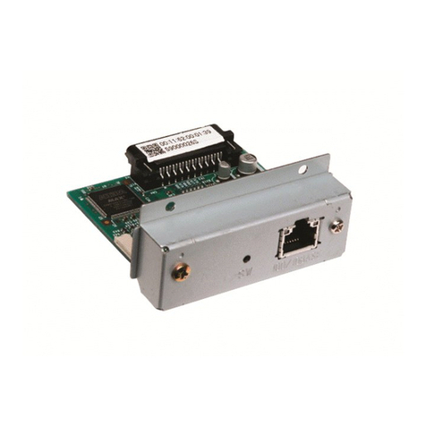
  9. Star Micronics IFBD-BE05 User manual

Star Micronics IFBD-BE05 User manual

1. インターフェイスボードの取り付け
① プリンタの電源スイッチをオフにして、ACアダプタ用電源ケーブルのプラグを
コンセントから抜いてください。
② 3本のネジを取り外してください。
③ プリンタ背面のブラインドプレートを取り外してください。
④ インタ−フェイスボ−ドをプリンタに差し込んでください。
注記) プリンタのコネクタとインタ−フェイスボ−ドのコネクタが接続するよう
に、しっかりと差し込んでください。
⑤ 取り外した3本のネジを使ってインタ−フェイスボ−ドを固定してください。
⑥インターフェイスボードを接続後、イーサネットケーブルを接続する前に一度、
自己印字を行ってください。 正しく接続されていれば、Interface : 100/10BASE
と印刷します。
2. 初期化の設定
設定情報を初期化する場合は、プッシュスイッチを以下のようにしてください。
通常動作中状態にて、プッシュスイッチを 1 秒~ 5 秒の間、押してください。緑色
と赤色の LED が規則的な点滅状態となります。
この状態からさらにもう一度短くプッシュスイッチを押すと、赤・緑色の両方の LED
が消灯状態となり、インターフェイスボードの設定が工場出荷時の設定に戻ります。
インターフェイスボードの初期化が終了した後、自動的にプリンタにリブートがか
かります。
このオプションボ
−
ドは、下記のプリンタ用インタ
−
フェイスボ
−
ドです。
下記の手順で取り付けてください。
インタ
−
フェイスボ
−
ド 適用プリンタ
IFBD
-
BE05..... イ
ー
サネット FVP10 シリ
ー
ズ
インタ
−
フェイスボ
−
ドの取り付け
80876440 IFBD-BE05
©スター精密株式会社 2010
3. LED の表示
 緑色 (100M)..........ポートが 100Mbps で動作しているときに点灯します。
 赤色 (Link/Activity)..........ポートと接続機器とのリンクが確立し、相互に通信が可
 能な状態にある時に点灯します。
4. イーサネットケーブルの接続
イーサネットケーブルは添付されていませんので、仕様に合ったケーブルをご用意く
ださい。電波障害防止のため、添付のフェライトコアのうち2ヶをプリンタ側とルー
タ (ハブ )側のケーブルに以下の手順で取り付けてください。
残りの1ヶはハードウェアマニュアルを参照して外部機器に取り付けてください。
① プリンタの電源が OFF になっていることをご確
認ください。
② 図のようにイーサネットケーブルにフェライト
コアを取り付けてください。
③ フェライトコアにソクセンバンドを通してくだ
さい。
④ ソクセンバンドをイーサネットケーブルにひと
巻きして、とめてください。はさみを使ってソ
クセンバンドの余った部分を切り落としてくだ
さい。
⑤ インターフェイスボードのコネクタにイーサ
ネットケーブルを挿入してください。そしてイー
サネットケーブルのもう一方をホストコンピュー
タのイーサネットポート用コネクタに挿入して
ください。
⑥ 自己印字を行うと、インタ
−
フェイスボ
−
ドの各
種設定と動作中の IP アドレスを確認できます。
DC
24V
SW
100/10BASE
DC
24V
イーサネット
   ケーブル
フェライトコア
ソクセンバンド
最大 35mm
100/10BASE
SW
LED
プッシュスイッチ
4. ConnectingtheEthernetCable
Note that the Ethernet cable is not provided. Please use a cable that meets specica-
tions. To protect the printer from electromagnetic interference, afx the three ferrite
cores that came with the Ethernet interface board, the rst on the printer end of the
cable and the second on the router (hub) end. Follow the instructions given below.
Afx the third ferrite core to the peripheral drive cable by reference to the Hardware
Manual.
(1) Make sure the printer is turned off.
(2) Afx the ferrite core onto the Ethernet cable as shown in the illustration.
(3) Pass the fastener through the ferrite core.
(4) Loop the fastener around the cable and lock it. Use scissors to cut off any excess.
(5) Connect the Ethernet cable to the connector on the interface board. Then, connect
the other end of the cable to your computer.
(6) You can check the settngs of the interface board and the IP address by running a
self-print.
This is an optional interface board for the following printers.
Use the following procedure to install the interface board.
InterfaceBoard Applicableprinter
IFBD-BE05 ........ Ethernet FVP10
Series
1. Replacingtheinterfaceboard
(1) Make sure that the AC adapter’s power cable plug is not connected to the outlet.
(2) Remove the three screws.
(3) Remove the blind plate in the direction of the arrow.
(4) Slide the new interface board into the printer until it is rmly seated.
Note: Insert the interface board so that it connects with the connector.
(5) Secure the interface board using the three screws that you removed in step 2.
(6) Once the interface board has been connected, perform a self-print test before con-
necting the Ethernet cable. Also, make sure that the printer recognizes the inter-
face board. When recognized: Prints “Interface: 100/10 BASE”.
2. InitializingSettings
Set the push switches as described below to initialize the setting information. Push
the switches for one to ve seconds while running under normal operating mode. The
green and red LEDs will ash with a regular pattern.
After that, push the switches once again in that state to turn OFF both of the red and
green LEDS. This will return the settings of the interface board to their default, or
ex-factory, settings. After the interface board has been initialized, the printer will au-
tomatically reboot itself.
3. LEDDisplay
Green (100M): Lights when the port is operating at 100 Mbps.
Red (Link/Activity): Lights when a link of the port and connected device is es-
tablished, and both are ready to communicate.
Installing the Interface Board
80876440 IFBD-BE05
© Copyright 2010 Star Micronics Co., Ltd.
DC
24V
SW
100/10BASE
DC
24V
Ferrite core
Ethernet cable
Fastener
100/10BASE
SW
3.5 cm
(maximum)
Push switch
LED

Other Star Micronics Computer Hardware manuals

Star Micronics Parallel Interface Unit IP-NPC User manual

Star Micronics

Star Micronics Parallel Interface Unit IP-NPC User manual

Star Micronics Serial Interface Unit IS-NP192 User manual

Star Micronics

Star Micronics Serial Interface Unit IS-NP192 User manual

Star Micronics IFBD-HE07X User manual

Star Micronics

Star Micronics IFBD-HE07X User manual

Popular Computer Hardware manuals by other brands

Supermicro BPN-SAS3-LA26A-N12 user guide

Supermicro

Supermicro BPN-SAS3-LA26A-N12 user guide

Ashly SWAMP 4-8SP operating manual

Ashly

Ashly SWAMP 4-8SP operating manual

Ingenic XBurst 2 CPU Core Programming manual

Ingenic

Ingenic XBurst 2 CPU Core Programming manual

Honeywell 66 Configuration guides

Honeywell

Honeywell 66 Configuration guides

SIGMA TEK CCP 621 manual

SIGMA TEK

SIGMA TEK CCP 621 manual

DirectOut Technologies EXBOX.GPIO manual

DirectOut Technologies

DirectOut Technologies EXBOX.GPIO manual

Digilent chipKIT MX3 Reference manual

Digilent

Digilent chipKIT MX3 Reference manual

Epson S5U1C62N51E1 manual

Epson

Epson S5U1C62N51E1 manual

Lexicon MPX - ADDENDUM REV 1 manual

Lexicon

Lexicon MPX - ADDENDUM REV 1 manual

American Dynamics ADQUAD27 Installation and operation

American Dynamics

American Dynamics ADQUAD27 Installation and operation

Sonnet TEMPO SATA E4P quick start guide

Sonnet

Sonnet TEMPO SATA E4P quick start guide

BE QUIET! PSU SHROUD quick start guide

BE QUIET!

BE QUIET! PSU SHROUD quick start guide

Sony HKPF-1125A Operation manual

Sony

Sony HKPF-1125A Operation manual

ekwb EK-FCS10000 INSTALLATION AND MOUNTING MANUAL

ekwb

ekwb EK-FCS10000 INSTALLATION AND MOUNTING MANUAL

Audiovox Verizon Wireless PC CARD PC 5220 user guide

Audiovox

Audiovox Verizon Wireless PC CARD PC 5220 user guide

EK-Quantum Momentum2 ROG Strix X570-i Gaming D-RGB user guide

EK-Quantum

EK-Quantum Momentum2 ROG Strix X570-i Gaming D-RGB user guide

Kingston Technology KHX16C10B1RK2/16X Specifications

Kingston Technology

Kingston Technology KHX16C10B1RK2/16X Specifications

Measurement Computing PCI-DAS1602/16 user guide

Measurement Computing

Measurement Computing PCI-DAS1602/16 user guide

manuals.online logo
manuals.online logoBrands
  • About & Mission
  • Contact us
  • Privacy Policy
  • Terms and Conditions

Copyright 2025 Manuals.Online. All Rights Reserved.